UDS2100 - Quick Start Guide
Page 6
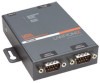
... Guide. Select one of the following LEDs are on the top of the UDS2100: ‹ Power / Diagnostic (Blue) ‹ RX Serial 1 Activity LED (Green) ‹ TX Serial 1 Activity LED (Yellow) ‹ RX Serial 2 Activity LED (Green) ‹ TX Serial 2 Activity LED ... knowledge base at www.lantronix.com/support Lantronix 15353 Barranca Parkway, Irvine, CA 92618, USA Phone: (949) 453-3990 or Fax: (949) 453-3995 www.lantronix.com WWW.LANTRONIX.COM 9 Double-click the unit in the device list, it can be configured. 1. Quick Start Guide UDS2100 CONFIGURE THE UDS2100 Once the UDS2100 is in the list...
... Guide. Select one of the following LEDs are on the top of the UDS2100: ‹ Power / Diagnostic (Blue) ‹ RX Serial 1 Activity LED (Green) ‹ TX Serial 1 Activity LED (Yellow) ‹ RX Serial 2 Activity LED (Green) ‹ TX Serial 2 Activity LED ... knowledge base at www.lantronix.com/support Lantronix 15353 Barranca Parkway, Irvine, CA 92618, USA Phone: (949) 453-3990 or Fax: (949) 453-3995 www.lantronix.com WWW.LANTRONIX.COM 9 Double-click the unit in the device list, it can be configured. 1. Quick Start Guide UDS2100 CONFIGURE THE UDS2100 Once the UDS2100 is in the list...
UDS2100 - User Guide
Page 6
... Reserved Port Numbers 44 Table 7-5. Disconnect Mode Options 52 Table 7-8. Problems and Error Messages 69 Table 13-1. UDS2100 Technical Specifications 74 UDS2100 User Guide 6 Sample Hardware Address 12 Figure 3-1. Channel Serial Settings 28 Figure 4-6. BootP/DHCP/AutoIP options 39...2-1. Common Interface Mode Settings 43 Table 7-3. Monitor Mode Commands 65 Table 11-1. Diagnostic, Power, and Serial Port LEDs 68 Figure 12-1. Serial Port Settings 42 Figure 7-3. Lantronix Web Manager 22 Figure 4-2. Chapter Summary 7 Table 3-1. Firmware Files 61 Table 10...
... Reserved Port Numbers 44 Table 7-5. Disconnect Mode Options 52 Table 7-8. Problems and Error Messages 69 Table 13-1. UDS2100 Technical Specifications 74 UDS2100 User Guide 6 Sample Hardware Address 12 Figure 3-1. Channel Serial Settings 28 Figure 4-6. BootP/DHCP/AutoIP options 39...2-1. Common Interface Mode Settings 43 Table 7-3. Monitor Mode Commands 65 Table 11-1. Diagnostic, Power, and Serial Port LEDs 68 Figure 12-1. Serial Port Settings 42 Figure 7-3. Lantronix Web Manager 22 Figure 4-2. Chapter Summary 7 Table 3-1. Firmware Files 61 Table 10...

UDS2100 - User Guide
Page 20
... 2. Select 9 to hold down the x key at the terminal (or emulation) while powering up , the self-test begins and the red Diagnostic LED starts blinking. After power-up the unit. 3. Note: The easiest way to enter Setup Mode is to save and exit Setup Mode. ...serial port. Connect a console terminal or a PC running a terminal emulation program to enter three lowercase x characters. You have one of the unit. UDS2100 User Guide 20 To configure the unit using a serial connection: 1. The Setup Mode window displays. 2. Continue with 5: Configuration via Telnet or Serial ...
... 2. Select 9 to hold down the x key at the terminal (or emulation) while powering up , the self-test begins and the red Diagnostic LED starts blinking. After power-up the unit. 3. Note: The easiest way to enter Setup Mode is to save and exit Setup Mode. ...serial port. Connect a console terminal or a PC running a terminal emulation program to enter three lowercase x characters. You have one of the unit. UDS2100 User Guide 20 To configure the unit using a serial connection: 1. The Setup Mode window displays. 2. Continue with 5: Configuration via Telnet or Serial ...

UDS2100 - User Guide
Page 64
... (xxx.xxx.xxx.xxx). Entering Monitor Mode Using the Network Port To enter Monitor Mode using the network. Many commands have successfully entered Monitor Mode. UDS2100 User Guide 64 b) Type yyy (or yy1) to the configuration port (9999). 2. There are available in capital letters. Follow the same steps used for setting... connections. Establish a Telnet session to enter Monitor Mode without network connections. If you enter the IP address, the command is a command-line interface used for diagnostic purposes.
... (xxx.xxx.xxx.xxx). Entering Monitor Mode Using the Network Port To enter Monitor Mode using the network. Many commands have successfully entered Monitor Mode. UDS2100 User Guide 64 b) Type yyy (or yy1) to the configuration port (9999). 2. There are available in capital letters. Follow the same steps used for setting... connections. Establish a Telnet session to enter Monitor Mode without network connections. If you enter the IP address, the command is a command-line interface used for diagnostic purposes.

UDS2100 - User Guide
Page 65
... does not broadcast its SSID, only the BSSID and RSSI are not overwritten). Get configuration from memory page Gets a memory page of the DNS Server UDS2100 User Guide 65 TCP Connection Table Shows all incoming and outgoing TCP connections. 10: Monitor Mode Command VS x.x.x.x GC x.x.x.x SC x.x.x.x PI x.x.x.x AT TT NC ... software header record (16 bytes) of unit with IP address x.x.x.x. Send Configuration Sets configuration of unit with IP address x.x.x.x from the device. Quit Exits diagnostics mode. Reports any stations found, including BSSID, SSID, and RSSI.
... does not broadcast its SSID, only the BSSID and RSSI are not overwritten). Get configuration from memory page Gets a memory page of the DNS Server UDS2100 User Guide 65 TCP Connection Table Shows all incoming and outgoing TCP connections. 10: Monitor Mode Command VS x.x.x.x GC x.x.x.x SC x.x.x.x PI x.x.x.x AT TT NC ... software header record (16 bytes) of unit with IP address x.x.x.x. Send Configuration Sets configuration of unit with IP address x.x.x.x from the device. Quit Exits diagnostics mode. Reports any stations found, including BSSID, SSID, and RSSI.

UDS2100 - User Guide
Page 67
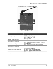
... 100 Mbps = Green) Ethernet Activities LED on the right (Bi-color, Half Duplex = Yellow, Full Duplex = Green) UDS2100 User Guide 67 11: Troubleshooting and Contact Information This chapter discusses how you are using a good network connection. Note: Some ...unexplained errors might be caused by duplicate IP addresses on the top of the UDS2100: Power / Diagnostic (Blue) RX Serial 1 Activity LED (Green) TX Serial 1 Activity LED (Yellow) RX Serial 2 Activity LED (Green... to the serial port while diagnosing an error to contact a dealer or Lantronix.
... 100 Mbps = Green) Ethernet Activities LED on the right (Bi-color, Half Duplex = Yellow, Full Duplex = Green) UDS2100 User Guide 67 11: Troubleshooting and Contact Information This chapter discusses how you are using a good network connection. Note: Some ...unexplained errors might be caused by duplicate IP addresses on the top of the UDS2100: Power / Diagnostic (Blue) RX Serial 1 Activity LED (Green) TX Serial 1 Activity LED (Yellow) RX Serial 2 Activity LED (Green... to the serial port while diagnosing an error to contact a dealer or Lantronix.
UDS2100 - User Guide
Page 68
... established Off = No data activity Ethernet Activity LED on the right (Bi-color) Blinking Yellow = Half Duplex data activity Blinking Green = Full Duplex data activity UDS2100 User Guide 68 11: Troubleshooting and Contact Information Figure 11-1. Diagnostic, Power, and Serial Port LEDs LEDs Table 11-1.
... established Off = No data activity Ethernet Activity LED on the right (Bi-color) Blinking Yellow = Half Duplex data activity Blinking Green = Full Duplex data activity UDS2100 User Guide 68 11: Troubleshooting and Contact Information Figure 11-1. Diagnostic, Power, and Serial Port LEDs LEDs Table 11-1.

UDS2100 - User Guide
Page 75
... Port Redirector, Windows® 98/NT/2000/XP-based virtual com port software Power 10/100 Mb Link on RJ45 10/100 Activity on RJ45 Diagnostic RX Serial 1 Activity TX Serial 1 Activity RX Serial 2 Activity TX Serial 2 Activity FCC Part 15 Subpart B Class A Radiated Emissions 30MHz - 1000MHz ICES-003 Issue 4 February... Serial Port: 15 KV ESD protection on RS232 and RS422/485 transceivers Power Input: Up to non-repeated 600 W 10/100 usec pulse protection against UDS2100 User Guide 75
... Port Redirector, Windows® 98/NT/2000/XP-based virtual com port software Power 10/100 Mb Link on RJ45 10/100 Activity on RJ45 Diagnostic RX Serial 1 Activity TX Serial 1 Activity RX Serial 2 Activity TX Serial 2 Activity FCC Part 15 Subpart B Class A Radiated Emissions 30MHz - 1000MHz ICES-003 Issue 4 February... Serial Port: 15 KV ESD protection on RS232 and RS422/485 transceivers Power Input: Up to non-repeated 600 W 10/100 usec pulse protection against UDS2100 User Guide 75
