UDS1100/UDS2100 - Product Brief
Page 2
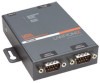
... DIN-rail mount UDS1100 ACDIN2001-01 DIN-rail mount UDS2100 CORPORATE HEADQUARTERS 167 Technology Drive | Irvine | CA 92618 | USA | t: 800.422.7055 | f: 949.450.7232 | sales@lantronix.com | www.lantronix.com ©2009, Lantronix, Inc. Lantronix is a registered trademark, and DeviceInstaller, Evolution OS ...SNMP TCP, UDP, and Telnet, TFTP, RFC2217 + LED Indicators • Power, Link, Activity, RX Activity, TX Activity + Processor • CPU: Lantronix DSTNI-EX 48 MHz clock • Memory: 256 KB SRAM, 2 MB Flash + Power Requirements • Input supply: 9-30 VDC (PoE only ...
... DIN-rail mount UDS1100 ACDIN2001-01 DIN-rail mount UDS2100 CORPORATE HEADQUARTERS 167 Technology Drive | Irvine | CA 92618 | USA | t: 800.422.7055 | f: 949.450.7232 | sales@lantronix.com | www.lantronix.com ©2009, Lantronix, Inc. Lantronix is a registered trademark, and DeviceInstaller, Evolution OS ...SNMP TCP, UDP, and Telnet, TFTP, RFC2217 + LED Indicators • Power, Link, Activity, RX Activity, TX Activity + Processor • CPU: Lantronix DSTNI-EX 48 MHz clock • Memory: 256 KB SRAM, 2 MB Flash + Power Requirements • Input supply: 9-30 VDC (PoE only ...
UDS2100 - Quick Start Guide
Page 3
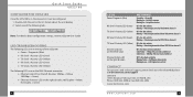
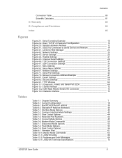
... the same subnet as described in Assign IP Address. DHCP Many networks use an automatic method of Lantronix devices on the network. (See Add the Unit to the Manage List.) If the UDS2100 does not acquire an IP, or you do not use the DeviceInstaller software to the list of... an IP address called DHCP. FIXED IP ADDRESS In most installations, a fixed IP address is desirable. IP Address: Subnet Mask: Gateway: WWW.LANTRONIX.COM 3 The UDS2100 looks for a DHCP server when it to search the network for the IP your network. This Quick Start explains how to and communicate over...
... the same subnet as described in Assign IP Address. DHCP Many networks use an automatic method of Lantronix devices on the network. (See Add the Unit to the Manage List.) If the UDS2100 does not acquire an IP, or you do not use the DeviceInstaller software to the list of... an IP address called DHCP. FIXED IP ADDRESS In most installations, a fixed IP address is desirable. IP Address: Subnet Mask: Gateway: WWW.LANTRONIX.COM 3 The UDS2100 looks for a DHCP server when it to search the network for the IP your network. This Quick Start explains how to and communicate over...

UDS2100 - Quick Start Guide
Page 4
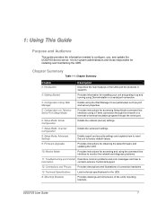
...into your CD-ROM drive. Click the Start button on the Task Bar and select Run. Figure 1. Figure 2. Quick Start Guide UDS2100 CONNECT 1. Connect the external power supply (9 to the installation wizard prompts. 4 ASSIGN IP ADDRESS AND NETWORK CLASS 1. Confirm that... device. If the CD does not launch automatically: a) Click the Start button on the Task Bar and select Programs ➜ Lantronix ➜ DeviceInstaller ➜ DeviceInstaller. The DeviceInstaller window displays. DeviceInstaller Window 2. The Device Identification window displays. Enter the Hardware address...
...into your CD-ROM drive. Click the Start button on the Task Bar and select Run. Figure 1. Figure 2. Quick Start Guide UDS2100 CONNECT 1. Connect the external power supply (9 to the installation wizard prompts. 4 ASSIGN IP ADDRESS AND NETWORK CLASS 1. Confirm that... device. If the CD does not launch automatically: a) Click the Start button on the Task Bar and select Programs ➜ Lantronix ➜ DeviceInstaller ➜ DeviceInstaller. The DeviceInstaller window displays. DeviceInstaller Window 2. The Device Identification window displays. Enter the Hardware address...

UDS2100 - Quick Start Guide
Page 5
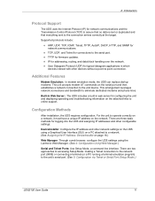
Assignment Method 6 ASSIGN IP ADDRESS CONTINUED Figure 4. Click Next. 6. Figure 5. Click Next. Click the Assign button to enable BOOTP, DHCP or Auto IP on the device. Figure 3. Assignment WWW.LANTRONIX.COM 7 Select Assign a specific IP address to assign a static IP address to the device, or select Obtain an IP address automatically to finalize the IP assignment. IP Settings 5. Enter the IP address, subnet mask, and gateway for the device in XXX.XXX.XXX.XXX format. Quick Start Guide UDS2100 ASSIGN IP ADDRESS CONTINUED... 4.
Assignment Method 6 ASSIGN IP ADDRESS CONTINUED Figure 4. Click Next. 6. Figure 5. Click Next. Click the Assign button to enable BOOTP, DHCP or Auto IP on the device. Figure 3. Assignment WWW.LANTRONIX.COM 7 Select Assign a specific IP address to assign a static IP address to the device, or select Obtain an IP address automatically to finalize the IP assignment. IP Settings 5. Enter the IP address, subnet mask, and gateway for the device in XXX.XXX.XXX.XXX format. Quick Start Guide UDS2100 ASSIGN IP ADDRESS CONTINUED... 4.
UDS2100 - Quick Start Guide
Page 6
... active Off = No data activity Blinking = Data being received by UDS2100 on channel 1 Off = No data activity Blinking = Data being transmitted from UDS2100 on channel 1 Off = No data activity Blinking = Data being received by UDS2100 on channel 2 Off = No data activity Blinking = Data being ...Barranca Parkway, Irvine, CA 92618, USA Phone: (949) 453-3990 or Fax: (949) 453-3995 www.lantronix.com WWW.LANTRONIX.COM 9 Details about configuration settings, see the UDS2100 User Guide. Select one of the UDS2100: ‹ Power / Diagnostic (Blue) ‹ RX Serial 1 Activity LED (Green) ‹ TX ...
... active Off = No data activity Blinking = Data being received by UDS2100 on channel 1 Off = No data activity Blinking = Data being transmitted from UDS2100 on channel 1 Off = No data activity Blinking = Data being received by UDS2100 on channel 2 Off = No data activity Blinking = Data being ...Barranca Parkway, Irvine, CA 92618, USA Phone: (949) 453-3990 or Fax: (949) 453-3995 www.lantronix.com WWW.LANTRONIX.COM 9 Details about configuration settings, see the UDS2100 User Guide. Select one of the UDS2100: ‹ Power / Diagnostic (Blue) ‹ RX Serial 1 Activity LED (Green) ‹ TX ...
UDS2100 - User Guide
Page 2
... sales offices, go to the Lantronix Web site at http://www.lantronix.com/about/contact/index.html Revisions Date 9/06 5/07 8/08 1/09 Rev. Contacts Lantronix 15353 Barranca Parkway Irvine, CA 92618..., USA Phone: 949-453-3990 Fax: 949-453-3995 Technical Support Online: www.lantronix.com/support Phone: (800) 422-7044 (US Only) (949) 453-7198 Sales... to reflect firmware v. 6.5, including UDP Broadcast; All rights reserved. Copyright & Trademark © 2007, 2008 Lantronix. Ethernet is a trademark of Microsoft Corp. No part of the contents of this book may be transmitted or...
... sales offices, go to the Lantronix Web site at http://www.lantronix.com/about/contact/index.html Revisions Date 9/06 5/07 8/08 1/09 Rev. Contacts Lantronix 15353 Barranca Parkway Irvine, CA 92618..., USA Phone: 949-453-3990 Fax: 949-453-3995 Technical Support Online: www.lantronix.com/support Phone: (800) 422-7044 (US Only) (949) 453-7198 Sales... to reflect firmware v. 6.5, including UDP Broadcast; All rights reserved. Copyright & Trademark © 2007, 2008 Lantronix. Ethernet is a trademark of Microsoft Corp. No part of the contents of this book may be transmitted or...
UDS2100 - User Guide
Page 6
..., and Serial Port LEDs 68 Figure 12-1. Interface Mode Options 43 Table 7-2. Firmware Files 61 Table 10-1. UDS2100 Technical Specifications 74 UDS2100 User Guide 6 Serial Tunneling Example 10 Figure 2-2. Network Settings 23 Figure 4-3. Hostlist Settings 27 Figure 4-5. Network...Figure 12-2. UDP Connection Settings 34 Figure 5-1. Common Interface Mode Settings 43 Table 7-3. Pack Control Options 54 Table 9-1. Lantronix Web Manager 22 Figure 4-2. Modem Mode Commands 50 Table 7-7. Current Configuration 18 Table 6-1. Disconnect Mode Options 52 Table...
..., and Serial Port LEDs 68 Figure 12-1. Interface Mode Options 43 Table 7-2. Firmware Files 61 Table 10-1. UDS2100 Technical Specifications 74 UDS2100 User Guide 6 Serial Tunneling Example 10 Figure 2-2. Network Settings 23 Figure 4-3. Hostlist Settings 27 Figure 4-5. Network...Figure 12-2. UDP Connection Settings 34 Figure 5-1. Common Interface Mode Settings 43 Table 7-3. Pack Control Options 54 Table 9-1. Lantronix Web Manager 22 Figure 4-2. Modem Mode Commands 50 Table 7-7. Current Configuration 18 Table 6-1. Disconnect Mode Options 52 Table...
UDS2100 - User Guide
Page 7
1: Using This Guide Purpose and Audience This guide provides the information needed to Information contact Lantronix Technical Support. 12: Connections and Pinouts Provides descriptions and illustrations of the unit's mounting brackets. Chapter Summary...and diagnose problems. 11: Troubleshooting and Contact Describes common problems and error messages and how to configure, use, and update the UDS2100 device server. A: Mounting Brackets Provides drawings and dimensions of connection hardware. 13: Technical Specifications Lists technical specifications for installing and ...
1: Using This Guide Purpose and Audience This guide provides the information needed to Information contact Lantronix Technical Support. 12: Connections and Pinouts Provides descriptions and illustrations of the unit's mounting brackets. Chapter Summary...and diagnose problems. 11: Troubleshooting and Contact Describes common problems and error messages and how to configure, use, and update the UDS2100 device server. A: Mounting Brackets Provides drawings and dimensions of connection hardware. 13: Technical Specifications Lists technical specifications for installing and ...

UDS2100 - User Guide
Page 8
... UDS and setting up and running. DeviceInstaller Online Help "Live" Tutorials on the product CD or the Lantronix Web site (www.lantronix.com). Explain and demonstrate assigning an IP address to create a virtual com port. UDS2100 User Guide 8 Error! Document UDS1100/2100 Quick Start Description Provides the steps for converting binary values to...
... UDS and setting up and running. DeviceInstaller Online Help "Live" Tutorials on the product CD or the Lantronix Web site (www.lantronix.com). Explain and demonstrate assigning an IP address to create a virtual com port. UDS2100 User Guide 8 Error! Document UDS1100/2100 Quick Start Description Provides the steps for converting binary values to...

UDS2100 - User Guide
Page 10
... Configuration Note: For step-by extending the functionality of COM-port-based Windows™ applications. Virtual COM ports, mapped to remote device servers on the Lantronix web site: www.lantronix.com/support. UDS2100 User Guide 10 Figure 2-1.
... Configuration Note: For step-by extending the functionality of COM-port-based Windows™ applications. Virtual COM ports, mapped to remote device servers on the Lantronix web site: www.lantronix.com/support. UDS2100 User Guide 10 Figure 2-1.
UDS2100 - User Guide
Page 11
...point connection. Built-in Web Server: The UDS includes a built-in which devices interact with other network settings on the UDS using the Lantronix Web Manager. (See 4: Configuration Using Web Manager.) Serial and Telnet Ports: Use Setup Mode, a command line interface. Supported protocols include...troubleshooting information on the attached links to the unit's serial port. (See 5: Configuration via Telnet or Serial Port (Setup Mode).) UDS2100 User Guide 11 Configuration Methods After installation, the UDS requires configuration. TCP, UDP, and Telnet for connections to a network. (See...
...point connection. Built-in Web Server: The UDS includes a built-in which devices interact with other network settings on the UDS using the Lantronix Web Manager. (See 4: Configuration Using Web Manager.) Serial and Telnet Ports: Use Setup Mode, a command line interface. Supported protocols include...troubleshooting information on the attached links to the unit's serial port. (See 5: Configuration via Telnet or Serial Port (Setup Mode).) UDS2100 User Guide 11 Configuration Methods After installation, the UDS requires configuration. TCP, UDP, and Telnet for connections to a network. (See...
UDS2100 - User Guide
Page 12
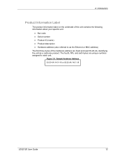
2: Introduction Product Information Label The product information label on the underside of the unit contains the following information about your specific unit: Bar code Serial number Product ID (name) Product description Hardware address (also referred to each unit. Sample Hardware Address 00-20-4A-14-01-18 or 00:20:4A:14:01:18 UDS2100 User Guide 12 The fourth, fifth, and sixth bytes are unique numbers assigned to as the Ethernet or MAC address) The first three bytes of the hardware address are fixed and read 00-20-4A, identifying the unit as a Lantronix product. Figure 2-3.
2: Introduction Product Information Label The product information label on the underside of the unit contains the following information about your specific unit: Bar code Serial number Product ID (name) Product description Hardware address (also referred to each unit. Sample Hardware Address 00-20-4A-14-01-18 or 00:20:4A:14:01:18 UDS2100 User Guide 12 The fourth, fifth, and sixth bytes are unique numbers assigned to as the Ethernet or MAC address) The first three bytes of the hardware address are fixed and read 00-20-4A, identifying the unit as a Lantronix product. Figure 2-3.
UDS2100 - User Guide
Page 16
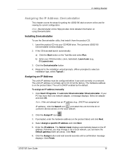
The Lantronix UDS2100 DeviceInstaller window displays. 2. Click the DeviceInstaller button. 4. Click Start Programs Lantronix DeviceInstaller DeviceInstaller. If your PC has more detailed information on the Task Bar and select Run. Note: If the unit already has an IP ... The unit's IP address must be configured before it from the list of Lantronix device servers on the local network. 2. Select an adapter and click OK. if desired, you can work correctly on the product label. UDS2100 User Guide 16 Installing DeviceInstaller To use the DeviceInstaller utility, first install it...
The Lantronix UDS2100 DeviceInstaller window displays. 2. Click the DeviceInstaller button. 4. Click Start Programs Lantronix DeviceInstaller DeviceInstaller. If your PC has more detailed information on the Task Bar and select Run. Note: If the unit already has an IP ... The unit's IP address must be configured before it from the list of Lantronix device servers on the local network. 2. Select an adapter and click OK. if desired, you can work correctly on the product label. UDS2100 User Guide 16 Installing DeviceInstaller To use the DeviceInstaller utility, first install it...
UDS2100 - User Guide
Page 17
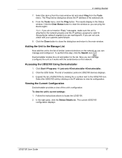
... the unit is attached to the list of similar Lantronix devices on the network. Select the UDS2100 unit by clicking the + symbol next to the list. Viewing the Current Configuration DeviceInstaller provides a view of available Lantronix UDS2100 devices displays. 3. In the right pane, click... the Device Details tab. The Ping Device dialog box shows the IP address of UDS2100s by clicking on its configuration. Click the Clear Status ...
... the unit is attached to the list of similar Lantronix devices on the network. Select the UDS2100 unit by clicking the + symbol next to the list. Viewing the Current Configuration DeviceInstaller provides a view of available Lantronix UDS2100 devices displays. 3. In the right pane, click... the Device Details tab. The Ping Device dialog box shows the IP address of UDS2100s by clicking on its configuration. Click the Clear Status ...
UDS2100 - User Guide
Page 21
... must set the way the unit will respond to serial and network traffic, how it will need it to locate the UDS2100 using DeviceInstaller. Click Start Programs Lantronix DeviceInstaller DeviceInstaller. Expand the list of the hardware (MAC) address. If the PC has more information on the hardware address...or Serial Port (Setup Mode). The Web Manager displays. Note: The examples in this chapter, we describe how to configure the UDS2100 using Web Manager, Lantronix's browser-based configuration tool. (For information on the product CD to install and run DeviceInstaller. 1.
... must set the way the unit will respond to serial and network traffic, how it will need it to locate the UDS2100 using DeviceInstaller. Click Start Programs Lantronix DeviceInstaller DeviceInstaller. Expand the list of the hardware (MAC) address. If the PC has more information on the hardware address...or Serial Port (Setup Mode). The Web Manager displays. Note: The examples in this chapter, we describe how to configure the UDS2100 using Web Manager, Lantronix's browser-based configuration tool. (For information on the product CD to install and run DeviceInstaller. 1.
UDS2100 - User Guide
Page 22
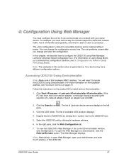
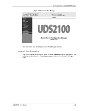
Lantronix Web Manager The main menu is in the left pane of the Web Manager window. The following sections describe the configurable parameters on the Network Settings page. Network Configuration The unit's network values display when you select Network from the main menu. 4: Configuration Using Web Manager Figure 4-1. UDS2100 User Guide 22
Lantronix Web Manager The main menu is in the left pane of the Web Manager window. The following sections describe the configurable parameters on the Network Settings page. Network Configuration The unit's network values display when you select Network from the main menu. 4: Configuration Using Web Manager Figure 4-1. UDS2100 User Guide 22

UDS2100 - User Guide
Page 34
... Address Table The table is enabled when Datagram Type is not to accept incoming UDP datagrams. The default setting is 00. Note: Lantronix Tech Support supports Datagram type 01. UDS2100 User Guide 34 Enter 01 for OEM use. 3. Select Yes to broadcast. Use Broadcast Select to identify units on the local network...
... Address Table The table is enabled when Datagram Type is not to accept incoming UDP datagrams. The default setting is 00. Note: Lantronix Tech Support supports Datagram type 01. UDS2100 User Guide 34 Enter 01 for OEM use. 3. Select Yes to broadcast. Use Broadcast Select to identify units on the local network...

UDS2100 - User Guide
Page 36
... Configuration, and 8: Setup Mode: Advanced Settings. The series of prompts at any time. The unit performs a reset after the configuration has been changed and stored. UDS2100 User Guide 36 Note: The menus in nonvolatile memory and is available from the main window list, and click the Telnet Configuration tab. As an... a Telnet connection to configure the unit over the network, establish a Telnet connection to access Telnet. Skip steps 1 and 2. To complete the configuration, continue with your Lantronix Sales Associate.
... Configuration, and 8: Setup Mode: Advanced Settings. The series of prompts at any time. The unit performs a reset after the configuration has been changed and stored. UDS2100 User Guide 36 Note: The menus in nonvolatile memory and is available from the main window list, and click the Telnet Configuration tab. As an... a Telnet connection to configure the unit over the network, establish a Telnet connection to access Telnet. Skip steps 1 and 2. To complete the configuration, continue with your Lantronix Sales Associate.

UDS2100 - User Guide
Page 47
... until it connects, the unit stops trying to connect to the Lantronix web server if the (www.lantronix.com) is configured in DNS lookup. The hostlist is started with host 121.2.4.5, port 1. C0.0.0.0/0 Enters Monitor Mode. UDS2100 User Guide 47 The port number can include a destination port number... string character (which is "C"), the subsequent character string is interpreted as well. C5 Connects to another IP in the hostlist table. Cwww.lantronix.com/80 Tries to connect to any others. Once it is able to connect to 129.1.2.5, port 1234. The unit does not accept ...
... until it connects, the unit stops trying to connect to the Lantronix web server if the (www.lantronix.com) is configured in DNS lookup. The hostlist is started with host 121.2.4.5, port 1. C0.0.0.0/0 Enters Monitor Mode. UDS2100 User Guide 47 The port number can include a destination port number... string character (which is "C"), the subsequent character string is interpreted as well. C5 Connects to another IP in the hostlist table. Cwww.lantronix.com/80 Tries to connect to any others. Once it is able to connect to 129.1.2.5, port 1234. The unit does not accept ...

UDS2100 - User Guide
Page 48
The menu shows you are deleted. 3. If you enter an IP address of times the Lantronix unit should wait before failing an attempted connection. The default setting is stored as Broadcast option. The default is not to edit the hostlist again. 4. ...: Channel Configuration Figure 4-7. d) Datagram Type Directed UDP When selecting this option, you a list of seconds the unit should try to make a good network connection to 3. 5. UDS2100 User Guide 48 The time is 250. Hostlist Option To enable the hostlist: 1.
The menu shows you are deleted. 3. If you enter an IP address of times the Lantronix unit should wait before failing an attempted connection. The default setting is stored as Broadcast option. The default is not to edit the hostlist again. 4. ...: Channel Configuration Figure 4-7. d) Datagram Type Directed UDP When selecting this option, you a list of seconds the unit should try to make a good network connection to 3. 5. UDS2100 User Guide 48 The time is 250. Hostlist Option To enable the hostlist: 1.


