UDS2100 - Quick Start Guide
Page 2
UDS2100 UDS2100 QUICK START CONTENTS What's In the Box 2 Pinouts 2 IP Addressing 3 Connect 4 Install the DeviceInstaller GUI 4 Assign IP Address 5-7 Configure the UDS2100 8 Troubleshoot 8-9 Contact 9
UDS2100 UDS2100 QUICK START CONTENTS What's In the Box 2 Pinouts 2 IP Addressing 3 Connect 4 Install the DeviceInstaller GUI 4 Assign IP Address 5-7 Configure the UDS2100 8 Troubleshoot 8-9 Contact 9
UDS2100 - Quick Start Guide
Page 3
...Address. Two ways to assign an IP address are unsure whether your network uses DHCP, check with UDS2100 User Guide and utilities (DeviceInstaller and Com Port Redirector) • Quick Start Guide UDS2100 PINOUTS 2 IP ADDRESSING Your unit must be within a valid range, unique to DB9F Null Modem Cable ...unit as your systems administrator. For more detailed information or alternative configuration methods, refer to the UDS2100 User Guide on the network. (See Add the Unit to the list of Lantronix devices on the CD. You can use the DeviceInstaller software to search the network for a...
...Address. Two ways to assign an IP address are unsure whether your network uses DHCP, check with UDS2100 User Guide and utilities (DeviceInstaller and Com Port Redirector) • Quick Start Guide UDS2100 PINOUTS 2 IP ADDRESSING Your unit must be within a valid range, unique to DB9F Null Modem Cable ...unit as your systems administrator. For more detailed information or alternative configuration methods, refer to the UDS2100 User Guide on the network. (See Add the Unit to the list of Lantronix devices on the CD. You can use the DeviceInstaller software to search the network for a...
UDS2100 - User Guide
Page 5
...: Troubleshooting and Contact Information 67 LEDs 67 Problems and Error Messages 69 Technical Support 71 12: Connections and Pinouts 72 UDS2100 Serial Ports 72 Serial Connector Pinouts 72 Network Port 73 Reset Button 73 Ethernet Connector Pinouts 73 Power Plug 73 13: Technical Specifications 74 A: Mounting Brackets 77 B: Alternative Ways to Assign an IP...
...: Troubleshooting and Contact Information 67 LEDs 67 Problems and Error Messages 69 Technical Support 71 12: Connections and Pinouts 72 UDS2100 Serial Ports 72 Serial Connector Pinouts 72 Network Port 73 Reset Button 73 Ethernet Connector Pinouts 73 Power Plug 73 13: Technical Specifications 74 A: Mounting Brackets 77 B: Alternative Ways to Assign an IP...
UDS2100 - User Guide
Page 7
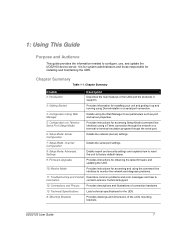
.... Chapter Summary Table 1-1. A: Mounting Brackets Provides drawings and dimensions of the unit's mounting brackets. UDS2100 User Guide 7 1: Using This Guide Purpose and Audience This guide provides the information needed to Information contact Lantronix Technical Support. 12: Connections and Pinouts Provides descriptions and illustrations of connection hardware. 13: Technical Specifications Lists technical specifications for...
.... Chapter Summary Table 1-1. A: Mounting Brackets Provides drawings and dimensions of the unit's mounting brackets. UDS2100 User Guide 7 1: Using This Guide Purpose and Audience This guide provides the information needed to Information contact Lantronix Technical Support. 12: Connections and Pinouts Provides descriptions and illustrations of connection hardware. 13: Technical Specifications Lists technical specifications for...
UDS2100 - User Guide
Page 72
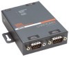
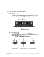
... two Male DB9 DTE connectors provide an RS-232C/RS-422 (4-wire)/ RS-485 (2-wire) interface. 12: Connections and Pinouts UDS2100 Serial Ports The UDS2100 has two male DB9 DTE serial ports that support RS-232C/RS-422 (4wire)/RS-485 (2-wire) serial standards up to 230 Kbps (and up ...
... two Male DB9 DTE connectors provide an RS-232C/RS-422 (4-wire)/ RS-485 (2-wire) interface. 12: Connections and Pinouts UDS2100 Serial Ports The UDS2100 has two male DB9 DTE serial ports that support RS-232C/RS-422 (4wire)/RS-485 (2-wire) serial standards up to 230 Kbps (and up ...

UDS2100 - User Guide
Page 73
To reset the unit to the configuration and invokes a reset (internally). UDS2100 User Guide 73 Ethernet Connector Pinouts Power Plug Power input on the power plug is 9-30 VDC (center +) (1.8W maximum power). Place the end of a paper clip or similar object into ..., including clearing the network settings (IP address, gateway, and netmask are set to 00s). Release the button and remove the paper clip. 12: Connections and Pinouts Network Port The unit's back panel contains a 9-30VDC power plug and an RJ45 (10/100) Ethernet port.
To reset the unit to the configuration and invokes a reset (internally). UDS2100 User Guide 73 Ethernet Connector Pinouts Power Plug Power input on the power plug is 9-30 VDC (center +) (1.8W maximum power). Place the end of a paper clip or similar object into ..., including clearing the network settings (IP address, gateway, and netmask are set to 00s). Release the button and remove the paper clip. 12: Connections and Pinouts Network Port The unit's back panel contains a 9-30VDC power plug and an RJ45 (10/100) Ethernet port.
UDS2100 - User Guide
Page 85
... Disconnect time, 55 DNS server, 40 DNS Server, 24 Error messages, 69 Ethernet address, 12 Expert settings, 56 Firmware recovering, 62 upgrading, 61 Flow, 43 UDS2100 User Guide Flush Mode, 53 Gateway, 39 Getting started, 13 Hardware address, 12, 15 Host list settings Setup Mode, 47 Web-Manager, 26 Installation, 14..., 77 Netmask, 40 Network settings, 22 Setup Mode, 39 Web Manager, 22 Pack control, 53 Package contents, 13 Password channel, 55 enhanced, 59 Telnet, 40 Pinouts, 72 Port number, 44 85
... Disconnect time, 55 DNS server, 40 DNS Server, 24 Error messages, 69 Ethernet address, 12 Expert settings, 56 Firmware recovering, 62 upgrading, 61 Flow, 43 UDS2100 User Guide Flush Mode, 53 Gateway, 39 Getting started, 13 Hardware address, 12, 15 Host list settings Setup Mode, 47 Web-Manager, 26 Installation, 14..., 77 Netmask, 40 Network settings, 22 Setup Mode, 39 Web Manager, 22 Pack control, 53 Package contents, 13 Password channel, 55 enhanced, 59 Telnet, 40 Pinouts, 72 Port number, 44 85