UDS1100/UDS2100 - Product Brief
Page 2
...-rail mount UDS1100 ACDIN2001-01 DIN-rail mount UDS2100 CORPORATE HEADQUARTERS 167 Technology Drive | Irvine | CA 92618 | USA | t: 800.422.7055 | f: 949.450.7232 | sales@lantronix.com | www.lantronix.com ©2009, Lantronix, Inc. CD Includes: User Guide and Software... • Dimensions: 35.5 x 17.1 x 7.6 cm (14 x 6.75 x 3 in) • Weight: 1.5 kg (3.0 lbs) + Software • Windows 98/ME/NT/2000/XP/Vista (32-bit versions) DeviceInstaller configuration software, Com Port Redirector software and related utilities • Configuration Options: Web browser, Telnet...
...-rail mount UDS1100 ACDIN2001-01 DIN-rail mount UDS2100 CORPORATE HEADQUARTERS 167 Technology Drive | Irvine | CA 92618 | USA | t: 800.422.7055 | f: 949.450.7232 | sales@lantronix.com | www.lantronix.com ©2009, Lantronix, Inc. CD Includes: User Guide and Software... • Dimensions: 35.5 x 17.1 x 7.6 cm (14 x 6.75 x 3 in) • Weight: 1.5 kg (3.0 lbs) + Software • Windows 98/ME/NT/2000/XP/Vista (32-bit versions) DeviceInstaller configuration software, Com Port Redirector software and related utilities • Configuration Options: Web browser, Telnet...

UDS2100 - Quick Start Guide
Page 4
...does not launch automatically: a) Click the Start button on the Task Bar and select Programs ➜ Lantronix ➜ DeviceInstaller ➜ DeviceInstaller. DeviceInstaller Window 2. Connect the external power supply (9 to the installation wizard prompts. 4 ASSIGN IP ADDRESS AND ...ROM drive. Respond to 30 VDC, 2W maximum). 3. Quick Start Guide UDS2100 CONNECT 1. Figure 2. Confirm that one of the device. The Device Identification window displays. The DeviceInstaller window displays. WWW.LANTRONIX.COM 5 Click the Assign IP icon . Connect your Ethernet cable to ...
...does not launch automatically: a) Click the Start button on the Task Bar and select Programs ➜ Lantronix ➜ DeviceInstaller ➜ DeviceInstaller. DeviceInstaller Window 2. Connect the external power supply (9 to the installation wizard prompts. 4 ASSIGN IP ADDRESS AND ...ROM drive. Respond to 30 VDC, 2W maximum). 3. Quick Start Guide UDS2100 CONNECT 1. Figure 2. Confirm that one of the device. The Device Identification window displays. The DeviceInstaller window displays. WWW.LANTRONIX.COM 5 Click the Assign IP icon . Connect your Ethernet cable to ...
UDS2100 - User Guide
Page 2
...453-7198 Sales Offices For a current list of Netscape Communications Corporation. C Updated for firmware v6.6 D Reference to the Lantronix Web site at http://www.lantronix.com/about/contact/index.html Revisions Date 9/06 5/07 8/08 1/09 Rev. Comments A Initial document B Updated to ...go to documentation on Lantronix website; UNIX is a registered trademark of mounting brackets. added two more Monitor Mode commands and diagrams of The Open Group. Windows 95, Windows 98, Windows 2000, and Windows NT are trademarks of America. minor corrections UDS2100 User Guide 2 ...
...453-7198 Sales Offices For a current list of Netscape Communications Corporation. C Updated for firmware v6.6 D Reference to the Lantronix Web site at http://www.lantronix.com/about/contact/index.html Revisions Date 9/06 5/07 8/08 1/09 Rev. Comments A Initial document B Updated to ...go to documentation on Lantronix website; UNIX is a registered trademark of mounting brackets. added two more Monitor Mode commands and diagrams of The Open Group. Windows 95, Windows 98, Windows 2000, and Windows NT are trademarks of America. minor corrections UDS2100 User Guide 2 ...
UDS2100 - User Guide
Page 6
...Pack Control Options 54 Table 9-1. UDS2100 Technical Specifications 74 UDS2100 User Guide 6 Network Settings 23 Figure 4-3. Expert Settings 56 Figure 8-2. TFTP Window 62 Figure 11-1. Diagnostic, Power,...UDS2100 LEDs 68 Table 11-2. Problems and Error Messages 69 Table 13-1. TCP Connection Settings 31 Figure 4-7. Current Configuration 18 Table 6-1. Standard IP Network Netmasks 40 Table 7-1. Firmware Files 61 Table 10-1. DB9 Male RS232 Serial DTE Connector 72 Figure 12-3. Flow Control Options 44 Table 7-4. MAC Address 37 Figure 5-2. Lantronix...
...Pack Control Options 54 Table 9-1. UDS2100 Technical Specifications 74 UDS2100 User Guide 6 Network Settings 23 Figure 4-3. Expert Settings 56 Figure 8-2. TFTP Window 62 Figure 11-1. Diagnostic, Power,...UDS2100 LEDs 68 Table 11-2. Problems and Error Messages 69 Table 13-1. TCP Connection Settings 31 Figure 4-7. Current Configuration 18 Table 6-1. Standard IP Network Netmasks 40 Table 7-1. Firmware Files 61 Table 10-1. DB9 Male RS232 Serial DTE Connector 72 Figure 12-3. Flow Control Options 44 Table 7-4. MAC Address 37 Figure 5-2. Lantronix...

UDS2100 - User Guide
Page 8
... Disclaimer Documentation Update For the latest revision of this product document, please check our online documentation at www.lantronix.com/support/documentation.html. UDS2100 User Guide 8 Error! Additional Documentation The following information is available on using the Windows-based utility to create a virtual com port. Provides information on the product CD or the...
... Disclaimer Documentation Update For the latest revision of this product document, please check our online documentation at www.lantronix.com/support/documentation.html. UDS2100 User Guide 8 Error! Additional Documentation The following information is available on using the Windows-based utility to create a virtual com port. Provides information on the product CD or the...

UDS2100 - User Guide
Page 10
... TCP/IP or Redirector Configuration Note: For step-by extending the functionality of COM-port-based Windows™ applications. Figure 2-1. UDS2100 User Guide 10 Virtual COM ports, mapped to remote device servers on the Lantronix web site: www.lantronix.com/support. Serial Tunneling Example 2: Introduction The Com Port Redirector software included on the product...
... TCP/IP or Redirector Configuration Note: For step-by extending the functionality of COM-port-based Windows™ applications. Figure 2-1. UDS2100 User Guide 10 Virtual COM ports, mapped to remote device servers on the Lantronix web site: www.lantronix.com/support. Serial Tunneling Example 2: Introduction The Com Port Redirector software included on the product...
UDS2100 - User Guide
Page 16
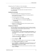
... Next. 5. if desired, you can work correctly on the local network. 2. UDS2100 User Guide 16 Installing DeviceInstaller To use the DeviceInstaller utility, first install it from the list of Lantronix device servers on a network. If the CD does not launch automatically: a) Click...and for viewing its current configuration. Note: DeviceInstaller online Help provides more than one network adapter, a message displays. The Lantronix UDS2100 DeviceInstaller window displays. 2. Enter the IP address. On a local network, you may change it can leave the Default gateway blank ...
... Next. 5. if desired, you can work correctly on the local network. 2. UDS2100 User Guide 16 Installing DeviceInstaller To use the DeviceInstaller utility, first install it from the list of Lantronix device servers on a network. If the CD does not launch automatically: a) Click...and for viewing its current configuration. Note: DeviceInstaller online Help provides more than one network adapter, a message displays. The Lantronix UDS2100 DeviceInstaller window displays. 2. Enter the IP address. On a local network, you may change it can leave the Default gateway blank ...
UDS2100 - User Guide
Page 17
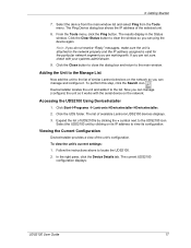
...The results display in the Status window. Click the Close button to close the dialog box and return to locate the UDS2100. 2. To perform this step, click the Search icon. Now you can ping the device again. Click Start Programs Lantronix DeviceInstaller DeviceInstaller. 2. Expand the ...you are not sure, check with . Viewing the Current Configuration DeviceInstaller provides a view of available Lantronix UDS2100 devices displays. 3. 3: Getting Started 7. Select the device from the main window list and select Ping from the Tools menu. The Ping Device dialog box shows the IP ...
...The results display in the Status window. Click the Close button to close the dialog box and return to locate the UDS2100. 2. To perform this step, click the Search icon. Now you can ping the device again. Click Start Programs Lantronix DeviceInstaller DeviceInstaller. 2. Expand the ...you are not sure, check with . Viewing the Current Configuration DeviceInstaller provides a view of available Lantronix UDS2100 devices displays. 3. 3: Getting Started 7. Select the device from the main window list and select Ping from the Tools menu. The Ping Device dialog box shows the IP ...
UDS2100 - User Guide
Page 19
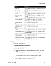
...a web browser, click the External Browser button. 3: Getting Started Setting Description Telnet Port Non-configurable field. Displays the UDS2100's port for telnet sessions. Firmware Upgradeable Non-configurable field. Supports Configurable Pins Non-configurable field. Displays False. Supports HTTP.... Supports GPIO Non-configurable field. To open the Web Manager in the current DeviceInstaller window, click the Go button. Supports HTTP Server Non-configurable field. UDS2100 supports a baud rate of 921600. Displays True. Supports 920K Baud Rate Non-configurable ...
...a web browser, click the External Browser button. 3: Getting Started Setting Description Telnet Port Non-configurable field. Displays the UDS2100's port for telnet sessions. Firmware Upgradeable Non-configurable field. Supports Configurable Pins Non-configurable field. Displays False. Supports HTTP.... Supports GPIO Non-configurable field. To open the Web Manager in the current DeviceInstaller window, click the Go button. Supports HTTP Server Non-configurable field. UDS2100 supports a baud rate of 921600. Displays True. Supports 920K Baud Rate Non-configurable ...

UDS2100 - User Guide
Page 20
... of the following: Continue with step 4 in 5: Configuration via Telnet or Serial Port (Setup Mode). Do one second to the unit's serial port. UDS2100 User Guide 20 The default serial port settings are 9600 baud, 8 bits, no parity, 1 stop bit, no flow control. 2. Enter the new IP... address, subnet mask, and gateway (if applicable). 5. The Setup Mode window displays. 2. To enter Setup Mode, cycle the unit's power (power off and back on). 3: Getting Started Note: Alternatively, to save and exit Setup Mode.
... of the following: Continue with step 4 in 5: Configuration via Telnet or Serial Port (Setup Mode). Do one second to the unit's serial port. UDS2100 User Guide 20 The default serial port settings are 9600 baud, 8 bits, no parity, 1 stop bit, no flow control. 2. Enter the new IP... address, subnet mask, and gateway (if applicable). 5. The Setup Mode window displays. 2. To enter Setup Mode, cycle the unit's power (power off and back on). 3: Getting Started Note: Alternatively, to save and exit Setup Mode.
UDS2100 - User Guide
Page 21
... via Telnet or Serial Port (Setup Mode). The list of Lantronix device servers displays in this chapter, we describe how to configure the UDS2100 using Web Manager, Lantronix's browser-based configuration tool. (For information on a network with... your web browser and enter the IP address of the UDS2100. Follow the instructions on page 15. Click the Search icon pane. . To view the UDS2100's Web Manager in nonvolatile memory and is stored in the current DeviceInstaller window...
... via Telnet or Serial Port (Setup Mode). The list of Lantronix device servers displays in this chapter, we describe how to configure the UDS2100 using Web Manager, Lantronix's browser-based configuration tool. (For information on a network with... your web browser and enter the IP address of the UDS2100. Follow the instructions on page 15. Click the Search icon pane. . To view the UDS2100's Web Manager in nonvolatile memory and is stored in the current DeviceInstaller window...
UDS2100 - User Guide
Page 22
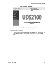
The following sections describe the configurable parameters on the Network Settings page. Lantronix Web Manager The main menu is in the left pane of the Web Manager window. UDS2100 User Guide 22 Network Configuration The unit's network values display when you select Network from the main menu. 4: Configuration Using Web Manager Figure 4-1.
The following sections describe the configurable parameters on the Network Settings page. Lantronix Web Manager The main menu is in the left pane of the Web Manager window. UDS2100 User Guide 22 Network Configuration The unit's network values display when you select Network from the main menu. 4: Configuration Using Web Manager Figure 4-1.
UDS2100 - User Guide
Page 30
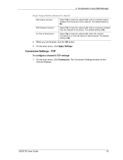
... to clear the output buffer with a connection initiated from the network to the device. The default setting is No. TCP To configure a channel's TCP settings: 1. UDS2100 User Guide 30 With Passive Connect Select Yes to clear the output buffer with a connection that is initiated from the device is No. The default...
... to clear the output buffer with a connection initiated from the network to the device. The default setting is No. TCP To configure a channel's TCP settings: 1. UDS2100 User Guide 30 With Passive Connect Select Yes to clear the output buffer with a connection that is initiated from the device is No. The default...

UDS2100 - User Guide
Page 33
...not asserted state. When you are finished, click the OK button. 4. UDP To configure a channel's UDP settings: 1. The Connection Settings window for the network connection to or from the serial port to disconnect (drop) when Modem Control In transitions from an asserted state to a ... disconnect request. To disable the inactivity timeout, enter 00:00. 3. In the available fields, enter or modify the following information: UDS2100 User Guide 33 Hard Disconnect When set an inactivity timeout. Inactivity Timeout Use this connection fails, the unit continues to scroll through the...
...not asserted state. When you are finished, click the OK button. 4. UDP To configure a channel's UDP settings: 1. The Connection Settings window for the network connection to or from the serial port to disconnect (drop) when Modem Control In transitions from an asserted state to a ... disconnect request. To disable the inactivity timeout, enter 00:00. 3. In the available fields, enter or modify the following information: UDS2100 User Guide 33 Hard Disconnect When set an inactivity timeout. Inactivity Timeout Use this connection fails, the unit continues to scroll through the...

UDS2100 - User Guide
Page 36
...described in the configuration chapters show a typical device. The unit's configuration is stored in nonvolatile memory and is available from the main window list, and click the Telnet Configuration tab. The unit performs a reset after the configuration has been changed and stored. Note: You ... configuration settings is called Setup Mode. Skip steps 1 and 2. UDS2100 User Guide 36 As an alternative to using it can use DeviceInstaller to access Telnet. To complete the configuration, continue with your Lantronix Sales Associate. The series of prompts at any time. This chapter...
...described in the configuration chapters show a typical device. The unit's configuration is stored in nonvolatile memory and is available from the main window list, and click the Telnet Configuration tab. The unit performs a reset after the configuration has been changed and stored. Note: You ... configuration settings is called Setup Mode. Skip steps 1 and 2. UDS2100 User Guide 36 As an alternative to using it can use DeviceInstaller to access Telnet. To complete the configuration, continue with your Lantronix Sales Associate. The series of prompts at any time. This chapter...
UDS2100 - User Guide
Page 37
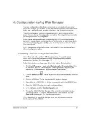
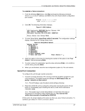
...(turning the power off and back on the menu by entering the number of resetting the UDS2100. Figure 5-2. Note: The easiest way to hold down the x key at bootup. 2. From the Windows Start menu, click Run and type the following information displays. Setup Menu Options 4. At this.... The following command, where x.x.x.x is the IP address, and 9999 is the unit's fixed network configuration port number: Windows: telnet x.x.x.x 9999 UNIX: telnet x.x.x.x:9999 2. Reset the UDS2100 unit by the Change Setup menu. To enter a value for a parameter, type the value and press Enter, or to...
...(turning the power off and back on the menu by entering the number of resetting the UDS2100. Figure 5-2. Note: The easiest way to hold down the x key at bootup. 2. From the Windows Start menu, click Run and type the following information displays. Setup Menu Options 4. At this.... The following command, where x.x.x.x is the IP address, and 9999 is the unit's fixed network configuration port number: Windows: telnet x.x.x.x 9999 UNIX: telnet x.x.x.x:9999 2. Reset the UDS2100 unit by the Change Setup menu. To enter a value for a parameter, type the value and press Enter, or to...
UDS2100 - User Guide
Page 40
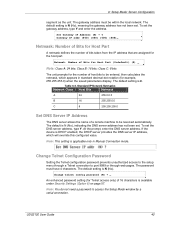
... Settings (Option 6) on page 57. The default is DHCP enabled, the DHCP server provides the DNS server IP address, which appears in Manual Connection mode. UDS2100 User Guide 40 Y Gateway IP addr (000) (000) (000) (000)_ Netmask: Number of Bits for Host Part A netmask defines the number of ...bits taken from the IP address that are assigned for Telnet access only) of host bits to access the Setup Mode window by a serial connection. Netmask: Number of a remote machine to port 9999 or through web pages. Standard IP Network Netmasks Network Class Host Bits ...
... Settings (Option 6) on page 57. The default is DHCP enabled, the DHCP server provides the DNS server IP address, which appears in Manual Connection mode. UDS2100 User Guide 40 Y Gateway IP addr (000) (000) (000) (000)_ Netmask: Number of Bits for Host Part A netmask defines the number of ...bits taken from the IP address that are assigned for Telnet access only) of host bits to access the Setup Mode window by a serial connection. Netmask: Number of a remote machine to port 9999 or through web pages. Standard IP Network Netmasks Network Class Host Bits ...

UDS2100 - User Guide
Page 62
... Guide 62 For Device Model, be sure the appropriate device (e.g., UDS2100) displays. To recover firmware: 1. From the Tools menu, select Advanced/Recover Firmware. Enter the following examples demonstrate the TFTP command sequence to ...the firmware is connected to complete, the unit performs a power reset. The Serial Port Firmware Upgrade window displays. 4. Select an adapter and click OK. 3. Figure 9-1. Connect the COM interface of the Lantronix unit. 5. TFTP Window 9: Firmware Upgrades After the firmware has been loaded and stored, which takes approximately 8 seconds to...
... Guide 62 For Device Model, be sure the appropriate device (e.g., UDS2100) displays. To recover firmware: 1. From the Tools menu, select Advanced/Recover Firmware. Enter the following examples demonstrate the TFTP command sequence to ...the firmware is connected to complete, the unit performs a power reset. The Serial Port Firmware Upgrade window displays. 4. Select an adapter and click OK. 3. Figure 9-1. Connect the COM interface of the Lantronix unit. 5. TFTP Window 9: Firmware Upgrades After the firmware has been loaded and stored, which takes approximately 8 seconds to...

UDS2100 - User Guide
Page 69
...logical subnet. The cause is closed . However, nothing happens when you try again." You did not choose the correct subnet mask. In Windows and usually in Unix, the segments of Unix, the Ethernet address is segmented with sufficient rights. The device server may only include numbers 0-9... and letters A-F. UDS2100 User Guide 69 When you are separated by the ARP method, the "Press Enter to assign is not properly plugged into Setup Mode"...
...logical subnet. The cause is closed . However, nothing happens when you try again." You did not choose the correct subnet mask. In Windows and usually in Unix, the segments of Unix, the Ethernet address is segmented with sufficient rights. The device server may only include numbers 0-9... and letters A-F. UDS2100 User Guide 69 When you are separated by the ARP method, the "Press Enter to assign is not properly plugged into Setup Mode"...

UDS2100 - User Guide
Page 75
... Multi-Master (IAP version only) Internal web server SNMP (read only) Serial login Telnet login DeviceInstaller software DeviceInstaller, Windows® 95/98/ME/NT/2000/XP-based configuration software Com Port Redirector, Windows® 98/NT/2000/XP-based virtual com port software Power 10/100 Mb Link on RJ45 10/100... Serial Port: 15 KV ESD protection on RS232 and RS422/485 transceivers Power Input: Up to non-repeated 600 W 10/100 usec pulse protection against UDS2100 User Guide 75
... Multi-Master (IAP version only) Internal web server SNMP (read only) Serial login Telnet login DeviceInstaller software DeviceInstaller, Windows® 95/98/ME/NT/2000/XP-based configuration software Com Port Redirector, Windows® 98/NT/2000/XP-based virtual com port software Power 10/100 Mb Link on RJ45 10/100... Serial Port: 15 KV ESD protection on RS232 and RS422/485 transceivers Power Input: Up to non-repeated 600 W 10/100 usec pulse protection against UDS2100 User Guide 75