
Owners Manual
Page 1
P/NO : 3828TUL259U(0407-REV00) Printed in Korea Internet Home Page : http://www.lgcommercial.com See the label attached on the back cover and quote this manual carefully before operating your dealer when you require service. Retain it for future reference. Record model number and serial number of the set . LCD Color Television OWNER'S MANUAL MODELS: RU-23LZ50C RU-30LZ50C RU-32LZ50C Please read this information to your set .
P/NO : 3828TUL259U(0407-REV00) Printed in Korea Internet Home Page : http://www.lgcommercial.com See the label attached on the back cover and quote this manual carefully before operating your dealer when you require service. Retain it for future reference. Record model number and serial number of the set . LCD Color Television OWNER'S MANUAL MODELS: RU-23LZ50C RU-30LZ50C RU-32LZ50C Please read this information to your set .
Owners Manual
Page 2
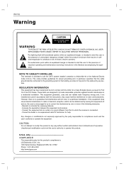
...uses and can be determined by the party responsible for this product. Reorient or relocate the receiving antenna. - Consult the dealer or an experienced radio/TV technician for a Class B digital device, pursuant to comply with the instructions, may be connected to the grounding system of the building, as close to Article 820-40 of the cable...in a particular installation. NO USER SERVICEABLE PARTS INSIDE. However, there is connected. - Any changes or modifications not expressly approved by turning the equipment off and on a circuit different from LG Electronics Corporation. U.S.A....
...uses and can be determined by the party responsible for this product. Reorient or relocate the receiving antenna. - Consult the dealer or an experienced radio/TV technician for a Class B digital device, pursuant to comply with the instructions, may be connected to the grounding system of the building, as close to Article 820-40 of the cable...in a particular installation. NO USER SERVICEABLE PARTS INSIDE. However, there is connected. - Any changes or modifications not expressly approved by turning the equipment off and on a circuit different from LG Electronics Corporation. U.S.A....

Owners Manual
Page 3
... moisture. Do not defeat the safety purpose of the polarized or grounding type plug. Do not install near water. 6. Read these instructions. 3. Do not use the attachments / accessories specified by qualified service personnel only. A grounding type plug has two blades and a third grounding prong. Only use this apparatus to dripping or splashing and no objects filled with one wider...
... moisture. Do not defeat the safety purpose of the polarized or grounding type plug. Do not install near water. 6. Read these instructions. 3. Do not use the attachments / accessories specified by qualified service personnel only. A grounding type plug has two blades and a third grounding prong. Only use this apparatus to dripping or splashing and no objects filled with one wider...

Owners Manual
Page 5
... Video 18 Manual Picture Control (User option 18 Cinema Mode Setup 18 Picture Format (ARC 18 Sound Menu Options EZ Audio 19 Equalizer Adjustments 19 AVL (Auto Volume Leveler 19 Sound Balance 20 Stereo/SAP Broadcasts Setup 20 Time Menu Options Auto Clock Setup 21 Manual Clock Setup 21 On/Off Timer Setup 22 Sleep Timer Setup 22 Auto Off 22 Special Menu Options Closed Captions 23 Caption/Text 24 Captions 24 Key Lock 24 Lock Menu Options Lock Menu Setup 26 PC Menu Options 27 External Control Device Setup 28 IR Codes 32 Maintenance 34 Product Specifications...
... Video 18 Manual Picture Control (User option 18 Cinema Mode Setup 18 Picture Format (ARC 18 Sound Menu Options EZ Audio 19 Equalizer Adjustments 19 AVL (Auto Volume Leveler 19 Sound Balance 20 Stereo/SAP Broadcasts Setup 20 Time Menu Options Auto Clock Setup 21 Manual Clock Setup 21 On/Off Timer Setup 22 Sleep Timer Setup 22 Auto Off 22 Special Menu Options Closed Captions 23 Caption/Text 24 Captions 24 Key Lock 24 Lock Menu Options Lock Menu Setup 26 PC Menu Options 27 External Control Device Setup 28 IR Codes 32 Maintenance 34 Product Specifications...

Owners Manual
Page 7
Introduction Connection Options 2 RU-23LZ50C only S-Video Input COMPONENT2 (DVD IN) (480i) Audio Input 1 PC Sound Input DVI Input (RGB Input) Video/Audio Input Antenna Input RS 232C Jack Remote Control Jack COMPONENT1 (DVD/DTV IN) ((480i/480p/720p/1080i), Audio) AC Input 7
Introduction Connection Options 2 RU-23LZ50C only S-Video Input COMPONENT2 (DVD IN) (480i) Audio Input 1 PC Sound Input DVI Input (RGB Input) Video/Audio Input Antenna Input RS 232C Jack Remote Control Jack COMPONENT1 (DVD/DTV IN) ((480i/480p/720p/1080i), Audio) AC Input 7

Owners Manual
Page 8
... p.23) ARC (Refer to the last channel you were watching. POWER MTS (Refer to p.20) MENU ENTER CH D / E (Channel button) VOL F / G (Volume button) VIDEO (Refer to p.18) SLEEP (Refer to p.22) FLASHBK Press the FLASHBK button to return to p.18) MULTIMEDIA Selects: TV, PC, Component 1 or Component 2 mode. Don't mix used batteries with correct polarity. • Install two 1.5V batteries of AAA type. When using the remote control, aim it at the remote control sensor...
... p.23) ARC (Refer to the last channel you were watching. POWER MTS (Refer to p.20) MENU ENTER CH D / E (Channel button) VOL F / G (Volume button) VIDEO (Refer to p.18) SLEEP (Refer to p.22) FLASHBK Press the FLASHBK button to return to p.18) MULTIMEDIA Selects: TV, PC, Component 1 or Component 2 mode. Don't mix used batteries with correct polarity. • Install two 1.5V batteries of AAA type. When using the remote control, aim it at the remote control sensor...

Owners Manual
Page 9
... Security System (RU-23LZ50C only) - Doing so may be a small "flicker" when when it for expensive electronic equipment such as notebook PCs and LCD projectors. Some minute dot defects may produce some temporary distortion effects on the screen, appearing as shown below. - Installation Installation Accessories Owner's Manual 1.5V 1.5V AAA Batteries Remote Control Power Cord DVI-D cable (PC) DVI to the user's guide provided with...
... Security System (RU-23LZ50C only) - Doing so may be a small "flicker" when when it for expensive electronic equipment such as notebook PCs and LCD projectors. Some minute dot defects may produce some temporary distortion effects on the screen, appearing as shown below. - Installation Installation Accessories Owner's Manual 1.5V 1.5V AAA Batteries Remote Control Power Cord DVI-D cable (PC) DVI to the user's guide provided with...

Owners Manual
Page 10
b. c. Align the holes on the TV back panel with the two tabs on the TV stand. Close cover. RU-23LZ50C only Adjusting the TV Viewing Angle - Remove the cover. d. Wire Holders - Install wires as shown. Reinstall the cover. RU-23LZ50C only 10 a. You can adjust the vertical angle of the TV. Installation Installation Instruction Rear A/V Cover * The connection panel is hidden behind the A/V cover. Thread, then pull the wires through the hole on the rear A/V cover as necessary.
b. c. Align the holes on the TV back panel with the two tabs on the TV stand. Close cover. RU-23LZ50C only Adjusting the TV Viewing Angle - Remove the cover. d. Wire Holders - Install wires as shown. Reinstall the cover. RU-23LZ50C only 10 a. You can adjust the vertical angle of the TV. Installation Installation Instruction Rear A/V Cover * The connection panel is hidden behind the A/V cover. Thread, then pull the wires through the hole on the rear A/V cover as necessary.

Owners Manual
Page 11
... picture quality, install a signal amplifier to the antenna as shown below. (Use the correct type of antenna cable for connection. If signal needs to an Outdoor Antenna Setup - VHF UHF Antenna Jack Signal Amplifier 11 External Equipment Connections Installation Antenna Connection - For optimum picture quality, adjust antenna direction. UHF Antenna 75Ω Round Cable Copper Wire Single Family Home 300Ω Flat Wire Antenna Converter - This type of wall antenna jack.) Turn clockwise to the right. - VHF Antenna Turn clockwise to an Inside Antenna Setup...
... picture quality, install a signal amplifier to the antenna as shown below. (Use the correct type of antenna cable for connection. If signal needs to an Outdoor Antenna Setup - VHF UHF Antenna Jack Signal Amplifier 11 External Equipment Connections Installation Antenna Connection - For optimum picture quality, adjust antenna direction. UHF Antenna 75Ω Round Cable Copper Wire Single Family Home 300Ω Flat Wire Antenna Converter - This type of wall antenna jack.) Turn clockwise to the right. - VHF Antenna Turn clockwise to an Inside Antenna Setup...

Owners Manual
Page 12
...TV Setup - After subscribing to Cable Box, match the jack colors (Video = yellow, Audio Left = white, and Audio Right = red). 2. When connecting the TV to a local cable TV service and installing a converter, you can watch cable TV programming. - Select channels with the cable box remote control. Use the TV/VIDEO button on the remote control to select Video. (If connected to the VCR owner's manual.) 3. Connection 2 1. Connection 2 1. Use the TV/VIDEO button on the VCR. (Refer to S-VIDEO on the TV. Tune the TV channel to the same channel number. Connection 1 Set...
...TV Setup - After subscribing to Cable Box, match the jack colors (Video = yellow, Audio Left = white, and Audio Right = red). 2. When connecting the TV to a local cable TV service and installing a converter, you can watch cable TV programming. - Select channels with the cable box remote control. Use the TV/VIDEO button on the remote control to select Video. (If connected to the VCR owner's manual.) 3. Connection 2 1. Connection 2 1. Use the TV/VIDEO button on the VCR. (Refer to S-VIDEO on the TV. Tune the TV channel to the same channel number. Connection 1 Set...

Owners Manual
Page 13
... an S-Video output jack, connect this to the S-VIDEO input on the TV. Refer to the DVD player's manual for operating instructions. • Component Input ports To get better picture quality, connect a DVD player to the AUDIO INPUT jacks on the remote control to select Component 1 or Component 2 (If connected to external A/V equipment, match the jack colors (Video = yellow, Audio Left = white, and Audio Right = red). Use the TV/VIDEO or MULTIMEDIA button on the TV, as shown below. When connecting the TV to S-VIDEO, select the S-Video input source.) 3. Turn on the DVD player...
... an S-Video output jack, connect this to the S-VIDEO input on the TV. Refer to the DVD player's manual for operating instructions. • Component Input ports To get better picture quality, connect a DVD player to the AUDIO INPUT jacks on the remote control to select Component 1 or Component 2 (If connected to external A/V equipment, match the jack colors (Video = yellow, Audio Left = white, and Audio Right = red). Use the TV/VIDEO or MULTIMEDIA button on the TV, as shown below. When connecting the TV to S-VIDEO, select the S-Video input source.) 3. Turn on the DVD player...

Owners Manual
Page 14
... PC. After setup, be supported. Connections 1. NOTES a. If you are using a PC with the PC cable. 3. Connections Connect the digital set-top box video outputs to the owner's manual for Horizontal and Vertical frequencies is separate. Use the TV/VIDEO or MULTIMEDIA button on the digital set-top box. (Refer to the COMPONENT (Y, PB, PR) jacks and connect the digital set -top box.) 2. c. Turn on the remote control to DPM mode. Viewing Setup 1. Set the monitor output resolution on the PC. 2. Connect the TV to the TV. 2. Using other formats (VGA...
... PC. After setup, be supported. Connections 1. NOTES a. If you are using a PC with the PC cable. 3. Connections Connect the digital set-top box video outputs to the owner's manual for Horizontal and Vertical frequencies is separate. Use the TV/VIDEO or MULTIMEDIA button on the digital set-top box. (Refer to the COMPONENT (Y, PB, PR) jacks and connect the digital set -top box.) 2. c. Turn on the remote control to DPM mode. Viewing Setup 1. Set the monitor output resolution on the PC. 2. Connect the TV to the TV. 2. Using other formats (VGA...

Owners Manual
Page 15
... all equipment connections. First select your desired language. From this time, the TV is switched to standby mode. • In standby mode, press the POWER, CH (D,E), TV/VIDEO, MULTIMEDIA or number button on the remote control or ON/OFF, CH (D,E), TV/VIDEO located on the TV to turn the TV off, press the on/off button located on the screen in the language of your local broadcast area. 3. Press the ENTER button to receive channels in your...
... all equipment connections. First select your desired language. From this time, the TV is switched to standby mode. • In standby mode, press the POWER, CH (D,E), TV/VIDEO, MULTIMEDIA or number button on the remote control or ON/OFF, CH (D,E), TV/VIDEO located on the TV to turn the TV off, press the on/off button located on the screen in the language of your local broadcast area. 3. Press the ENTER button to receive channels in your...

Owners Manual
Page 16
.... For Auto program to work, the programming source must be connected to save. The TV scans for auto program to select the Channel menu. 2. Add/Delete Channels with EZ scan - Press the G button and then use D / E button to complete the channel search cycle before choosing a channel. Press the ENTER button to the TV and the TV must be receiving programming signals either over -the-air channels and then channels provided by a cable service. The current channel number is displayed. Channel EZ Scan Manual prog. TV 30...
.... For Auto program to work, the programming source must be connected to save. The TV scans for auto program to select the Channel menu. 2. Add/Delete Channels with EZ scan - Press the G button and then use D / E button to complete the channel search cycle before choosing a channel. Press the ENTER button to the TV and the TV must be receiving programming signals either over -the-air channels and then channels provided by a cable service. The current channel number is displayed. Channel EZ Scan Manual prog. TV 30...
Owners Manual
Page 22
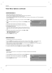
... TV turns off at turn -on the TV with the On-Timer function, the TV will not work . - Off timer On timer 3. The TV must be in standby mode for the On-Timer to select the Timer menu. Run: Off timer/On timer are set the hour. 4. Press the G button and then use D / E button to select On or Off. Timer function operates only if current time is no input signal, the TV switches to standby mode. 1. Press the G button and then use D / E button...
... TV turns off at turn -on the TV with the On-Timer function, the TV will not work . - Off timer On timer 3. The TV must be in standby mode for the On-Timer to select the Timer menu. Run: Off timer/On timer are set the hour. 4. Press the G button and then use D / E button to select On or Off. Timer function operates only if current time is no input signal, the TV switches to standby mode. 1. Press the G button and then use D / E button...
Owners Manual
Page 27
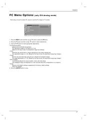
The range adjustment is 0~100. (Based on the screen background. Operation 27 Press the MENU button and then use D / E button to the default settings programmed at the factory; The adjustment range is 0~100. (Based on the input mode, the adjustment range may change.) • Clock Minimizes any horizontal noise and clear up /down. Press the ENTER button to make appropriate adjustments. • H-position/V-position Adjusts picture left/right and up or sharpen the...
The range adjustment is 0~100. (Based on the screen background. Operation 27 Press the MENU button and then use D / E button to the default settings programmed at the factory; The adjustment range is 0~100. (Based on the input mode, the adjustment range may change.) • Clock Minimizes any horizontal noise and clear up /down. Press the ENTER button to make appropriate adjustments. • H-position/V-position Adjusts picture left/right and up or sharpen the...

Owners Manual
Page 28
... on the Monitor back panel. - Pin name 1 No connection 2 RXD (Receive data) 3 TXD (Transmit data) 4 DTR (DTE side ready) 5 GND 6 DSR (DCE side ready) 7 RTS (Ready to send) 8 CTS (Clear to an external control device (such as a computer or an A/V control system) and control the Monitor's functions externally. - RS-232C connection cables are not supplied with the Monitor. D-Sub 9-Pin Male No. Connect the serial port of...
... on the Monitor back panel. - Pin name 1 No connection 2 RXD (Receive data) 3 TXD (Transmit data) 4 DTR (DTE side ready) 5 GND 6 DSR (DCE side ready) 7 RTS (Ready to send) 8 CTS (Clear to an external control device (such as a computer or an A/V control system) and control the Monitor's functions externally. - RS-232C connection cables are not supplied with the Monitor. D-Sub 9-Pin Male No. Connect the serial port of...

Owners Manual
Page 29
... communication errors. Data 1: Illegal Code 2: Not supported function 3: Wait more time 29 Press the G button and then use D / E button to adjust Set ID to save. Power 02. Sharpness 12. Tune Command 15. Adjustment range is 1 ~ 99. Set ID -- 4. Screen Mute 05. Volume Control 07. Add/Delete 16. External Control Device Setup Set ID - Special Language Caption/Text 2. Press the G button and then use D / E button to select Set ID. Input Select 03. Press the MENU button and then use D / E button...
... communication errors. Data 1: Illegal Code 2: Not supported function 3: Wait more time 29 Press the G button and then use D / E button to adjust Set ID to save. Power 02. Sharpness 12. Tune Command 15. Adjustment range is 1 ~ 99. Set ID -- 4. Screen Mute 05. Volume Control 07. Add/Delete 16. External Control Device Setup Set ID - Special Language Caption/Text 2. Press the G button and then use D / E button to select Set ID. Input Select 03. Press the MENU button and then use D / E button...
Owners Manual
Page 31
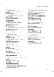
... lock the remote control and the front panel controls on 1: OSD mute off , remote control lock is released. 31 You can also adjust tint in the Picture menu. Acknowledgement [k][ ][Set ID][ ][OK][Data][x] 12. Transmission [k][l][ ][Set ID][ ][Data][Cr] Data 0: OSD mute on the TV. Refer User's Manual Acknowledgement [c][ ][Set ID][ ][OK][Data][x] 13. When main power is on/off Acknowledgement [l][ ][Set ID][ ][OK][Data][x] External Control Device Setup 14. Acknowledgement [i][ ][Set ID...
... lock the remote control and the front panel controls on 1: OSD mute off , remote control lock is released. 31 You can also adjust tint in the Picture menu. Acknowledgement [k][ ][Set ID][ ][OK][Data][x] 12. Transmission [k][l][ ][Set ID][ ][Data][Cr] Data 0: OSD mute on the TV. Refer User's Manual Acknowledgement [c][ ][Set ID][ ][OK][Data][x] 13. When main power is on/off Acknowledgement [l][ ][Set ID][ ][OK][Data][x] External Control Device Setup 14. Acknowledgement [i][ ][Set ID...
Owners Manual
Page 34
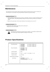
... to unplug the power cord to wipe the screen. 2. Be sure to use it air-dry before you leave your TV. Wet a soft cloth in a mixture of time you turn on your TV dormant for a while. Please be prevented. Maintenance & Product Specifications Maintenance - Extended Absence If you begin any cleaning. Product Specifications Power Requirement Power Consumption Television System Television Channel Television Screen External Antenna Impedance Audio Output RU-23LZ50C RU-30LZ50C RU-32LZ50C : AC 100...
... to unplug the power cord to wipe the screen. 2. Be sure to use it air-dry before you leave your TV. Wet a soft cloth in a mixture of time you turn on your TV dormant for a while. Please be prevented. Maintenance & Product Specifications Maintenance - Extended Absence If you begin any cleaning. Product Specifications Power Requirement Power Consumption Television System Television Channel Television Screen External Antenna Impedance Audio Output RU-23LZ50C RU-30LZ50C RU-32LZ50C : AC 100...


