

Service Manual
Page 34
YES Check IC204(1,8) and X200 when it is exited at IC202 (6,7)(FIG.04)(FIG.05). Is there any problem? Check if IC202(1) is low when HV sync is sine curve form « 27MHz clock.? Check HV sync. Check IC204(5) and IC206(1). (A) YES NO Is power supplied into HD2? YES NO END Check Power Supply part. YES Is Video Display Clock(IC206(7)) NO supplied into IC203? Fig.01 VDP Clock 3-25 YES Switch the Display Color into RGB/DVI.
YES Check IC204(1,8) and X200 when it is exited at IC202 (6,7)(FIG.04)(FIG.05). Is there any problem? Check if IC202(1) is low when HV sync is sine curve form « 27MHz clock.? Check HV sync. Check IC204(5) and IC206(1). (A) YES NO Is power supplied into HD2? YES NO END Check Power Supply part. YES Is Video Display Clock(IC206(7)) NO supplied into IC203? Fig.01 VDP Clock 3-25 YES Switch the Display Color into RGB/DVI.
Service Manual
Page 36
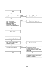
YES NG OK Go to (A) flow. In the case of (C1) _ DTV, NO Check if there is normal. Is there any problem? Check signal intensity. Check IC304 used in the composite & S-video out and IC303 used in the component YPbPr & RGB analog. NO END YES NG Check...tuner part. OK Check HD 2 interrupt request signal. YES Check analog buffers. Check Power Supply part. Check if system clock 27MHz comes from IC206(9), when signal is input stream. IC203(F11) 3-27 It is not OSD problem. NO Is there decoding problem? (B) YES Is analog component on the Mute mode? Check DVI output.
YES NG OK Go to (A) flow. In the case of (C1) _ DTV, NO Check if there is normal. Is there any problem? Check signal intensity. Check IC304 used in the composite & S-video out and IC303 used in the component YPbPr & RGB analog. NO END YES NG Check...tuner part. OK Check HD 2 interrupt request signal. YES Check analog buffers. Check Power Supply part. Check if system clock 27MHz comes from IC206(9), when signal is input stream. IC203(F11) 3-27 It is not OSD problem. NO Is there decoding problem? (B) YES Is analog component on the Mute mode? Check DVI output.


