
User Guide
Page 1
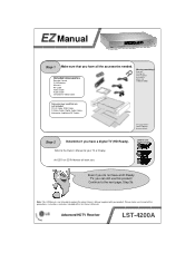
... Ready). Refer to replace the actual Owner's Manual supplied with your TV or Display. Note: This EZ Manual is not intended to the Owner's Manual for your product. Please make sure to the next page, Step 3b. Advanced HDTV Receiver LST-4200A EZ Manual Step 1 Make sure that are not included DVI-D Cable, RGB Cable, S-Video Cable, Digital Audio Cables, Attenuator, Additional RF Cables See page 8 of the Owner's Manual for more details...
... Ready). Refer to replace the actual Owner's Manual supplied with your TV or Display. Note: This EZ Manual is not intended to the Owner's Manual for your product. Please make sure to the next page, Step 3b. Advanced HDTV Receiver LST-4200A EZ Manual Step 1 Make sure that are not included DVI-D Cable, RGB Cable, S-Video Cable, Digital Audio Cables, Attenuator, Additional RF Cables See page 8 of the Owner's Manual for more details...
User Guide
Page 2
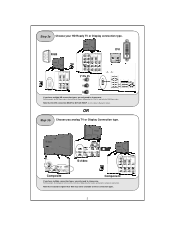
... one to choose, followed by the Y Pb Pr, and lastly the RGB Connection. S-video Composite Component If you have multiple HD connection types, you only need to choose one . Step 3a Choose your HD Ready TV or Display connection type. See the Owner's Manual for details. Note that resolutions higher than 480i may not be DVI with HDCP. Note that the DVI...
... one to choose, followed by the Y Pb Pr, and lastly the RGB Connection. S-video Composite Component If you have multiple HD connection types, you only need to choose one . Step 3a Choose your HD Ready TV or Display connection type. See the Owner's Manual for details. Note that resolutions higher than 480i may not be DVI with HDCP. Note that the DVI...
User Guide
Page 3
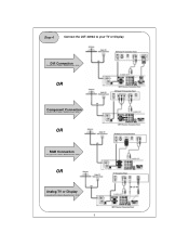
OR RGB Connection See pg13 of the Owner's Manual for more details. Step 4 Connect the LST-4200A to your TV or Display DVI Connection See pg14 of the Owner's Manual for more details. OR Component Connection See pg12 of the Owner's Manual for more details. 3 OR Analog TV or Display See pg113 of the Owner's Manual for more details.
OR RGB Connection See pg13 of the Owner's Manual for more details. Step 4 Connect the LST-4200A to your TV or Display DVI Connection See pg14 of the Owner's Manual for more details. OR Component Connection See pg12 of the Owner's Manual for more details. 3 OR Analog TV or Display See pg113 of the Owner's Manual for more details.
User Guide
Page 4
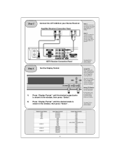
... compatible with your TV/Display. See page 17 of the Display Modes may be set to 480i in the window, then press "Select". Analog TV/Display: A standard analog TV can only display 480i Even though you can simply connect the Audio Outputs to your TV. You can see Menus. Step 5 Connect the LST-4200A to your Stereo Receiver Note 1: You only need to make adjustments. Step 6 Set the Display Format 1) Press "Display Format...
... compatible with your TV/Display. See page 17 of the Display Modes may be set to 480i in the window, then press "Select". Analog TV/Display: A standard analog TV can only display 480i Even though you can simply connect the Audio Outputs to your TV. You can see Menus. Step 5 Connect the LST-4200A to your Stereo Receiver Note 1: You only need to make adjustments. Step 6 Set the Display Format 1) Press "Display Format...
User Guide
Page 5
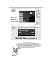
... switch between tuners! 5 Step 7 Scan for more details. There is at its highest level The LST-4200A will tune to get TV channels Select "CATV/CADTV" Note: Once the Channel Scan has completed, the LST-4200A will receive both Analog AND Digital TV channels. Antenna Input: If you are having low signal strength on 2) Press "Signal" on the Remote 3) Adjust your antenna so that the signal meter is no need to adjust...
... switch between tuners! 5 Step 7 Scan for more details. There is at its highest level The LST-4200A will tune to get TV channels Select "CATV/CADTV" Note: Once the Channel Scan has completed, the LST-4200A will receive both Analog AND Digital TV channels. Antenna Input: If you are having low signal strength on 2) Press "Signal" on the Remote 3) Adjust your antenna so that the signal meter is no need to adjust...
User Guide
Page 6
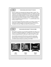
... channel however. In order to what channel number is on . Anytime you see a " - The QAM Tuner in a channel number, you are watching a Digital TV Channel. The LST-4200A will need to receive 6-1, 6-2, 6-3, etc. When this happens, you will receive the QAM Channels, as well as to help prevent viewers from being used, "Channel 6" must send their digital signal on Ch 6 for HD Cable TV. The LST-4200A is their Channel Number. Tip Understanding Cable Digital TV Channels...
... channel however. In order to what channel number is on . Anytime you see a " - The QAM Tuner in a channel number, you are watching a Digital TV Channel. The LST-4200A will need to receive 6-1, 6-2, 6-3, etc. When this happens, you will receive the QAM Channels, as well as to help prevent viewers from being used, "Channel 6" must send their digital signal on Ch 6 for HD Cable TV. The LST-4200A is their Channel Number. Tip Understanding Cable Digital TV Channels...
User Guide
Page 7
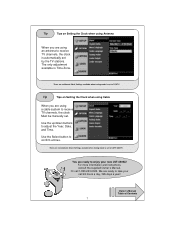
... buttons to enjoy your call 1-800-243-0000. For more information and instructions, consult the supplied Owner's Manual. We are using a cable system to receive TV channels, the clock Must be manually set by the TV stations. Tip Tips on Setting the Clock when using Antenna When you are ready to take your new LST-4200A! You are ready to adjust the Year, Date, and Time. The only adjustment...
... buttons to enjoy your call 1-800-243-0000. For more information and instructions, consult the supplied Owner's Manual. We are using a cable system to receive TV channels, the clock Must be manually set by the TV stations. Tip Tips on Setting the Clock when using Antenna When you are ready to take your new LST-4200A! You are ready to adjust the Year, Date, and Time. The only adjustment...
Service Manual
Page 1
... you know all service information, including parts, circuit control & maintenance and etc. P/NO : 3829RVN007H SERVICE MANUAL JUNE, 2004 Printed in the production stage at factory, which is required the high precision. That's why they are already controlled in Korea MODEL : LST-4200A Digital Set Top Box SERVICE MANUAL INTRODUCTION: This manual is to control mileage and the circuits except special case. When servicing the unit, please follow this manual. MODEL : LST-4200A
... you know all service information, including parts, circuit control & maintenance and etc. P/NO : 3829RVN007H SERVICE MANUAL JUNE, 2004 Printed in the production stage at factory, which is required the high precision. That's why they are already controlled in Korea MODEL : LST-4200A Digital Set Top Box SERVICE MANUAL INTRODUCTION: This manual is to control mileage and the circuits except special case. When servicing the unit, please follow this manual. MODEL : LST-4200A
Service Manual
Page 3
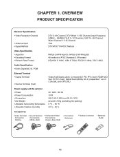
... Formats) HD(1920 X 1080i, 1280 X 720p), SD(720 X 480p, 720 X 480i) Audio Specification • Dolby Digital(AC-3), PCM External Terminal • Output Terminal • Service Terminal (1set) Video(1set)/Audio (2set), Component(Y, PB, PR) (1set), RGB/HV(DSub 15 Pin) (1set), Digital Sound(Dolby AC-3) (respective 1 set of COAXIAL and OPTICAL) Power supply and the exterior • Power • Power Consumption • Dimensions • Net Weight • Allowable Surrounding...
... Formats) HD(1920 X 1080i, 1280 X 720p), SD(720 X 480p, 720 X 480i) Audio Specification • Dolby Digital(AC-3), PCM External Terminal • Output Terminal • Service Terminal (1set) Video(1set)/Audio (2set), Component(Y, PB, PR) (1set), RGB/HV(DSub 15 Pin) (1set), Digital Sound(Dolby AC-3) (respective 1 set of COAXIAL and OPTICAL) Power supply and the exterior • Power • Power Consumption • Dimensions • Net Weight • Allowable Surrounding...
Service Manual
Page 4
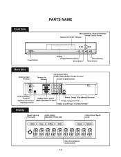
... Side PARTS NAME Menu Selection, Channel Selection, Volume Control Button Remote Controller Receiver Power Button Back Side Antenna Input Terminal Terminal for Service Display Output Selection Button Menu Button Cancel Button Enter Button Component Video (1080i/720p/480p/480i) Output Terminal Sound Output Terminal Antenna Output Terminal Digital Sound Output (Optical) Terminal RGB/HV Video Output (1080i/720p/480p) Terminal Monitor Output (Video/Sound) Terminal S-Video Output Terminal Digital Sound Output (Coaxial) Terminal Display Power Queuing Pilot Lamp Video Output Resolution...
... Side PARTS NAME Menu Selection, Channel Selection, Volume Control Button Remote Controller Receiver Power Button Back Side Antenna Input Terminal Terminal for Service Display Output Selection Button Menu Button Cancel Button Enter Button Component Video (1080i/720p/480p/480i) Output Terminal Sound Output Terminal Antenna Output Terminal Digital Sound Output (Optical) Terminal RGB/HV Video Output (1080i/720p/480p) Terminal Monitor Output (Video/Sound) Terminal S-Video Output Terminal Digital Sound Output (Coaxial) Terminal Display Power Queuing Pilot Lamp Video Output Resolution...
Service Manual
Page 5
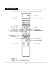
... running selected item or entering the set point. Enter( ) Button: Use it facing the receiver of Remote Controller on the front side of Digital Settopbox. Power Button Signal InPteonwsietyr BBuuttttoonn Display Size Button Power Button Number Button Power Display Size Signal Intensity Automatic Channel Add-on Power Button Automatic Channel Add-on the Menu Panel or entering the set point. Cancel Button : Use it when moving on Button Power Button -(PDoawsehr) BBuuttttoonn Caption ScPaonwneerr BBuuttttoonn Sound Selection Button Power Button All Broadcasting Button Button by...
... running selected item or entering the set point. Enter( ) Button: Use it facing the receiver of Remote Controller on the front side of Digital Settopbox. Power Button Signal InPteonwsietyr BBuuttttoonn Display Size Button Power Button Number Button Power Display Size Signal Intensity Automatic Channel Add-on Power Button Automatic Channel Add-on the Menu Panel or entering the set point. Cancel Button : Use it when moving on Button Power Button -(PDoawsehr) BBuuttttoonn Caption ScPaonwneerr BBuuttttoonn Sound Selection Button Power Button All Broadcasting Button Button by...
Service Manual
Page 7
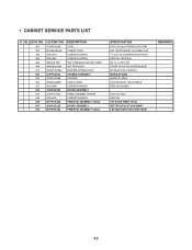
...6410REHK02A POWER CORD 463 353-051G SCREW,DRAWING 465 353-046K SCREW,DRAWING 466 1BK-0512391 BOLT,HEXAGON SOCKET HEAD 469 1NHD8220060 NUT,HEXAGON 470 1WSV1200084 WASHER,SPRING LOCK A44 3141R-0065J CHASSIS ASSEMBLY 260 3140R-0055B CHASSIS 320 3720R-D080E PANEL,VIDEO 457 ... 4 D3/8"-16 NO RULE BSP/BN,BSW/ NO RULE D12.0 SUS 304 MAIN(LST-3000) MAIN(LST-3000) VCR BACK(LST-3000) PRESS SPECIAL(3X8 BK.) VCR LST-3000 SPECIAL LST-3100Z TIMER TOTAL SETTOP BOX LST-3100 SMPS LST-3000 KOR ATSC+NTSC MAIN REMARKS 2-2 NO. LG PART NO. • CABINET SERVICE PARTS LIST S AL LOCA.
...6410REHK02A POWER CORD 463 353-051G SCREW,DRAWING 465 353-046K SCREW,DRAWING 466 1BK-0512391 BOLT,HEXAGON SOCKET HEAD 469 1NHD8220060 NUT,HEXAGON 470 1WSV1200084 WASHER,SPRING LOCK A44 3141R-0065J CHASSIS ASSEMBLY 260 3140R-0055B CHASSIS 320 3720R-D080E PANEL,VIDEO 457 ... 4 D3/8"-16 NO RULE BSP/BN,BSW/ NO RULE D12.0 SUS 304 MAIN(LST-3000) MAIN(LST-3000) VCR BACK(LST-3000) PRESS SPECIAL(3X8 BK.) VCR LST-3000 SPECIAL LST-3100Z TIMER TOTAL SETTOP BOX LST-3100 SMPS LST-3000 KOR ATSC+NTSC MAIN REMARKS 2-2 NO. LG PART NO. • CABINET SERVICE PARTS LIST S AL LOCA.

Service Manual
Page 10
Most communication programs can be properly setup, depending on the user environment.) 3. Set up properly "Setup © Terminal" like the display. (But, Port should be used, but TeraTerm is advised to use. 2. Generate the terminal for the serial communications - CHAPTER 3. Set "Setup © Serial Port" like the Figure. 3-1 CIRCUIT SW_UPDATE Method 1.
Most communication programs can be properly setup, depending on the user environment.) 3. Set up properly "Setup © Terminal" like the display. (But, Port should be used, but TeraTerm is advised to use. 2. Generate the terminal for the serial communications - CHAPTER 3. Set "Setup © Serial Port" like the Figure. 3-1 CIRCUIT SW_UPDATE Method 1.
Service Manual
Page 27
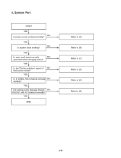
3. YES Is the CS(chip selection) signal of NO flash parts normal? YES Is it coming out the message through NO RS-232C, with PC terminal connected? Refer to (G). 3-18 Refer to (D). YES Is I2 C(SDA, SCL) channel normally NO working ? Refer to (E). Refer to (C). YES NO Is system clock working ? YES END Refer to (B). Refer to (A). YES Is each reset signal normally NO generated when charging power? System Part START YES NO Is power source working normally?
3. YES Is the CS(chip selection) signal of NO flash parts normal? YES Is it coming out the message through NO RS-232C, with PC terminal connected? Refer to (G). 3-18 Refer to (D). YES Is I2 C(SDA, SCL) channel normally NO working ? Refer to (E). Refer to (C). YES NO Is system clock working ? YES END Refer to (B). Refer to (A). YES Is each reset signal normally NO generated when charging power? System Part START YES NO Is power source working normally?
Service Manual
Page 41
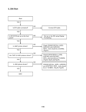
YES END Connect DVI cable. IDCK_ clock should be at 74.25MHz. IDCK_ clock should be at 27MHz. YES NO Are 720P & 1080I pictures shown? Check IC302(57(IDCK+), 2(DE), 4(HSYNC) and 5(VSYNC). IC302(57(IDCK+), 2(DE), 4(HSYNC) and 5(VSYNC)) IDCK_ clock should be at 13.5MHz. 3-32 5. YES Is DVI ICON set up on the front NO panel? Set up on the DVI using Display Format Key. Check IC302(57(IDCK+), 2(DE), 4(HSYNC) and 5(VSYNC). YES NO Is 480P picture shown? YES NO Is 480I picture shown? DVI Part Start YES NO Is DVI cable connected?
YES END Connect DVI cable. IDCK_ clock should be at 74.25MHz. IDCK_ clock should be at 27MHz. YES NO Are 720P & 1080I pictures shown? Check IC302(57(IDCK+), 2(DE), 4(HSYNC) and 5(VSYNC). IC302(57(IDCK+), 2(DE), 4(HSYNC) and 5(VSYNC)) IDCK_ clock should be at 13.5MHz. 3-32 5. YES Is DVI ICON set up on the front NO panel? Set up on the DVI using Display Format Key. Check IC302(57(IDCK+), 2(DE), 4(HSYNC) and 5(VSYNC). YES NO Is 480P picture shown? YES NO Is 480I picture shown? DVI Part Start YES NO Is DVI cable connected?
Service Manual
Page 43
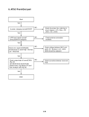
...-End part Start YES NO Is power charging normal(IC500)? YES END Check the power line, referring to circuit diagram. (+5V_Alive, +5V, +30V, +1.8, +3.3V) Check antenna connection condition. YES Is RF input signal normal? Check voltage between tuner and PCB. 3-34 Check connection between R511 and earth. 5V : Normal, 0~4V : Q501, Q502 should be replaced. NO (using spectrum analyzer) YES NO Check error signal...
...-End part Start YES NO Is power charging normal(IC500)? YES END Check the power line, referring to circuit diagram. (+5V_Alive, +5V, +30V, +1.8, +3.3V) Check antenna connection condition. YES Is RF input signal normal? Check voltage between tuner and PCB. 3-34 Check connection between R511 and earth. 5V : Normal, 0~4V : Q501, Q502 should be replaced. NO (using spectrum analyzer) YES NO Check error signal...
Service Manual
Page 45
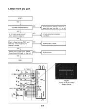
NO (Use spectrum analyzer) YES Check voltage between R511 and NO earth. 5V : Abnormal(Bad), 1V ( below) : Normal YES Check video output signal of NIM NO Tuner Tuner(IC500)(pin 16, Fig.04). Replace Q501, Q502. Replace tuner. 7. YES END Check power line, referring to circuit diagram. (+5V_Alive, +5V, +30V, +1.8, +3.3V) Check antenna connection condition. YES Is RF input signal normal? NTSC Front-End part START YES NO Is power charging normal? Fig.04 IC500(16) NTSC Video Output Signal 3-36
NO (Use spectrum analyzer) YES Check voltage between R511 and NO earth. 5V : Abnormal(Bad), 1V ( below) : Normal YES Check video output signal of NIM NO Tuner Tuner(IC500)(pin 16, Fig.04). Replace Q501, Q502. Replace tuner. 7. YES END Check power line, referring to circuit diagram. (+5V_Alive, +5V, +30V, +1.8, +3.3V) Check antenna connection condition. YES Is RF input signal normal? NTSC Front-End part START YES NO Is power charging normal? Fig.04 IC500(16) NTSC Video Output Signal 3-36
Service Manual
Page 64
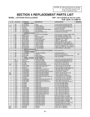
...PARTS *** 3110R-P020A CASE 6410RAHK02D POWER CORD 353-051G SCREW,DRAWING 353-046K SCREW,DRAWING 1BK-0512391 BOLT,HEXAGON SOCKET HEAD 1NHD8220060 NUT,HEXAGON 1WSV1200084 WASHER,SPRING LOCK *** PACKING ACCESSORY *** 3835RB0001P INSTRUCTION ASSEMBLY 3890R-C120M BOX 3920R-E062A PACKING,CASING 3858R-S001A SHEET (MECH) 6910R-AB02C BATTERY,ALKALINE 6611R1G003A PLUG ASSEMBLY 6611R2G003A PLUG ASSEMBLY 6850R-ZAC03 CABLE...SECTION 4 REPLACEMENT PARTS LIST MODEL : LST-4200A AA1ULL(LGEUS) NSP : Not avallable as service parts. NOTES) Warning Parts that are shaded are critical...
...PARTS *** 3110R-P020A CASE 6410RAHK02D POWER CORD 353-051G SCREW,DRAWING 353-046K SCREW,DRAWING 1BK-0512391 BOLT,HEXAGON SOCKET HEAD 1NHD8220060 NUT,HEXAGON 1WSV1200084 WASHER,SPRING LOCK *** PACKING ACCESSORY *** 3835RB0001P INSTRUCTION ASSEMBLY 3890R-C120M BOX 3920R-E062A PACKING,CASING 3858R-S001A SHEET (MECH) 6910R-AB02C BATTERY,ALKALINE 6611R1G003A PLUG ASSEMBLY 6611R2G003A PLUG ASSEMBLY 6850R-ZAC03 CABLE...SECTION 4 REPLACEMENT PARTS LIST MODEL : LST-4200A AA1ULL(LGEUS) NSP : Not avallable as service parts. NOTES) Warning Parts that are shaded are critical...
Service Manual
Page 65
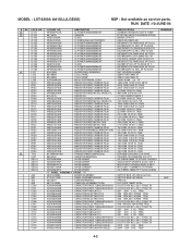
...LG PART NO. DESCRIPTION 0IPMGFF001A IC,POWER MANAGEMENT 657-063A SENSOR 0IKE431000A IC,KEC 0ISS431000A IC,SAMSUNG ELECTRONICS 0IPMGFA032A IC,POWER MANAGEMENT 0IPMGKE018A IC,POWER MANAGEMENT 0IPMGFA046A IC,POWER MANAGEMENT 0IPMGKE022B IC,POWER MANAGEMENT 0IPMGFA034A IC,POWER MANAGEMENT 0IPMGKE021B IC,POWER MANAGEMENT 0IPMGSH010A IC,POWER MANAGEMENT 0IPMGFA017A IC,POWER...3BSB 26MM TP PYUNG CHANG REMARKS SETTOP BOX LST-4200A AA1ULL SETTOP BOX LST-4200A SPECIAL LST-3100Z TIMER TOTAL 0.1UF D 50V...MODEL : LST-4200A AA1ULL(LGEUS) NSP : Not avallable as service parts. NO.
...LG PART NO. DESCRIPTION 0IPMGFF001A IC,POWER MANAGEMENT 657-063A SENSOR 0IKE431000A IC,KEC 0ISS431000A IC,SAMSUNG ELECTRONICS 0IPMGFA032A IC,POWER MANAGEMENT 0IPMGKE018A IC,POWER MANAGEMENT 0IPMGFA046A IC,POWER MANAGEMENT 0IPMGKE022B IC,POWER MANAGEMENT 0IPMGFA034A IC,POWER MANAGEMENT 0IPMGKE021B IC,POWER MANAGEMENT 0IPMGSH010A IC,POWER MANAGEMENT 0IPMGFA017A IC,POWER...3BSB 26MM TP PYUNG CHANG REMARKS SETTOP BOX LST-4200A AA1ULL SETTOP BOX LST-4200A SPECIAL LST-3100Z TIMER TOTAL 0.1UF D 50V...MODEL : LST-4200A AA1ULL(LGEUS) NSP : Not avallable as service parts. NO.
Service Manual
Page 66
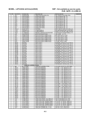
...,SWITCHING 0DD133009AA DIODE,SWITCHING 0DD133009AA DIODE,SWITCHING 0DD133009AA DIODE,SWITCHING 0DD133009AA DIODE,SWITCHING 0DD133009AA DIODE,SWITCHING 0DD133009AA DIODE,SWITCHING 0DD133009AA DIODE,SWITCHING 0DD133009AA DIODE,SWITCHING 6302R-V210A DIGITRON 0IPRPNE001A IC,PERIPHERALS 0IPRPPY002A IC,PERIPHERALS 6712R0838GA REMOTE CONTROLLER RECEIVER 0LR0102K035 INDUCTOR RADIAL LEAD 0RD8202F608 RESISTOR,FIXED CARBON FILM 0RD2200F608 RESISTOR,FIXED CARBON FILM 0RD1002F608 RESISTOR,FIXED CARBON FILM 0RD1002F608 RESISTOR,FIXED CARBON FILM 0RD1002F608 RESISTOR,FIXED...
...,SWITCHING 0DD133009AA DIODE,SWITCHING 0DD133009AA DIODE,SWITCHING 0DD133009AA DIODE,SWITCHING 0DD133009AA DIODE,SWITCHING 0DD133009AA DIODE,SWITCHING 0DD133009AA DIODE,SWITCHING 0DD133009AA DIODE,SWITCHING 0DD133009AA DIODE,SWITCHING 6302R-V210A DIGITRON 0IPRPNE001A IC,PERIPHERALS 0IPRPPY002A IC,PERIPHERALS 6712R0838GA REMOTE CONTROLLER RECEIVER 0LR0102K035 INDUCTOR RADIAL LEAD 0RD8202F608 RESISTOR,FIXED CARBON FILM 0RD2200F608 RESISTOR,FIXED CARBON FILM 0RD1002F608 RESISTOR,FIXED CARBON FILM 0RD1002F608 RESISTOR,FIXED CARBON FILM 0RD1002F608 RESISTOR,FIXED...


