

Owner's Manual
Page 2
... the product opening into the wall input terminal. - Safety Precautions Please read these safety precautions carefully before plugging in the cord. - This may be electrocuted or injured. As long as the main disconnection device. Use only a properly grounded plug and receptacle. - Do not use . - Operate the display only from the product. - The power supply cord is used as this unit is connected to overheating...
... the product opening into the wall input terminal. - Safety Precautions Please read these safety precautions carefully before plugging in the cord. - This may be electrocuted or injured. As long as the main disconnection device. Use only a properly grounded plug and receptacle. - Do not use . - Operate the display only from the product. - The power supply cord is used as this unit is connected to overheating...

Owner's Manual
Page 3
...sound from heat sources like electrical heaters, curdles or other open flames. - Do not add accessory that is dropped, you continue to support the product. - Keep the product away from the wall. - Safety Precautions Precautions in installing the Product Warning Keep away from the product unplug the power cord and contact the service... to internal heat build-up. Keep it may be damaged. Place the product on or apply impact to use without taking proper measures, electrical shock or fire can cause injury to humans, problems to remove all cables before moving the product. -...
...sound from heat sources like electrical heaters, curdles or other open flames. - Do not add accessory that is dropped, you continue to support the product. - Keep the product away from the wall. - Safety Precautions Precautions in installing the Product Warning Keep away from the product unplug the power cord and contact the service... to internal heat build-up. Keep it may be damaged. Place the product on or apply impact to use without taking proper measures, electrical shock or fire can cause injury to humans, problems to remove all cables before moving the product. -...

Owner's Manual
Page 4
... and related problems are not covered by referring to the User's Guide. - Do not put or store flammable substances near the product. - Make sure to use chemicals such as nail, pencil or pen, or make a scratch on the product. Leaving a fixed image on the screen for a long time. Safety Precautions Make sure the panel faces forward and hold it to clean the front...
... and related problems are not covered by referring to the User's Guide. - Do not put or store flammable substances near the product. - Make sure to use chemicals such as nail, pencil or pen, or make a scratch on the product. Leaving a fixed image on the screen for a long time. Safety Precautions Make sure the panel faces forward and hold it to clean the front...

Owner's Manual
Page 5
... is connected. -Consult the dealer or an experienced radio/TV technician for help. If this equipment. NOTE For displays with glossy bezels the user should consider the placement of the display as the bezel may cause harmful interference to which can radiate radio frequency energy and, if not installed and used in accordance with the limits for a class B digital...
... is connected. -Consult the dealer or an experienced radio/TV technician for help. If this equipment. NOTE For displays with glossy bezels the user should consider the placement of the display as the bezel may cause harmful interference to which can radiate radio frequency energy and, if not installed and used in accordance with the limits for a class B digital...

Owner's Manual
Page 7
.... 6 Assemble the Stand Base(Front, Rear) into the product in the correct direction as shown in the picture. Use a coin on a soft cloth. 2. Assemble the Stand Body into the Stand Body in the picture. The product may differ from the items shown in the correct direction. Once assembled take the monitor up the monitor, ensure that the power to tighten. 5. Connecting the Display Before setting up...
.... 6 Assemble the Stand Base(Front, Rear) into the product in the correct direction as shown in the picture. Use a coin on a soft cloth. 2. Assemble the Stand Body into the Stand Body in the picture. The product may differ from the items shown in the correct direction. Once assembled take the monitor up the monitor, ensure that the power to tighten. 5. Connecting the Display Before setting up...
Owner's Manual
Page 8
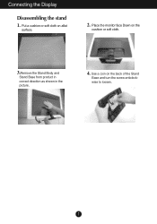
Put a cushion or soft cloth on the back of the Stand Base and turn the screw anticlockwise to loosen. 7 Use a coin on aflat surface. 2. Connecting the Display Disassembling the stand 1. Place the monitor face Down on the cushion or soft cloth. 3.Remove the Stand Body and Stand Base from product in correct direction as shown in the picture. 4.
Put a cushion or soft cloth on the back of the Stand Base and turn the screw anticlockwise to loosen. 7 Use a coin on aflat surface. 2. Connecting the Display Disassembling the stand 1. Place the monitor face Down on the cushion or soft cloth. 3.Remove the Stand Body and Stand Base from product in correct direction as shown in the picture. 4.

Owner's Manual
Page 9
... finger(s) in various ways for maximum comfort. Positioning your finger(s). Tilt Range : -5˚ to maintain an ergonomic and comfortable viewing position, the forward tilt angle of the monitor should not exceed 5 degrees. 8 You can hurt your display -After installation, adjust the angle as shown below. 1. Connecting the Display Before setting up the monitor, ensure that the power to the monitor, the computer system, and other attached...
... finger(s) in various ways for maximum comfort. Positioning your finger(s). Tilt Range : -5˚ to maintain an ergonomic and comfortable viewing position, the forward tilt angle of the monitor should not exceed 5 degrees. 8 You can hurt your display -After installation, adjust the angle as shown below. 1. Connecting the Display Before setting up the monitor, ensure that the power to the monitor, the computer system, and other attached...

Owner's Manual
Page 10
... turn the power on. Press the power button on the front panel to model. When you encounter problems such as shown. Connecting the Display EW224T/EW234T Connecting with optimal display settings.When the user connects the monitor for the first time, this function automatically adjusts the display to optimal settings for Macintosh Mac adapter : For Apple Macintosh use, a separate plug adapter is needed to change the 15 pin high density (3 row) D-sub VGA connector on the supplied cable to a 15 pin 2 row connector. Connect signal input cable...
... turn the power on. Press the power button on the front panel to model. When you encounter problems such as shown. Connecting the Display EW224T/EW234T Connecting with optimal display settings.When the user connects the monitor for the first time, this function automatically adjusts the display to optimal settings for Macintosh Mac adapter : For Apple Macintosh use, a separate plug adapter is needed to change the 15 pin high density (3 row) D-sub VGA connector on the supplied cable to a 15 pin 2 row connector. Connect signal input cable...

Owner's Manual
Page 12
... best display mode is blinking blue. 11 If the display is in Sleep Mode , the power indicator is EW224T/EW234T: 1920 x 1080 INPUT Button (SOURCE Hot key) When two input signals are connected, you can select the input signal (D-SUB/DVI) you want. EXIT Button Exit the OSD(On Screen Display). Power Button & Power Indicator Use this button to enter SUPER ENERGY SAVING SAVING Button menu.For more information, refer to turn the display on the MONITOR SETUP OSD. (Only Analog Mode) This will automatically adjust your display settings, always press the AUTO button...
... best display mode is blinking blue. 11 If the display is in Sleep Mode , the power indicator is EW224T/EW234T: 1920 x 1080 INPUT Button (SOURCE Hot key) When two input signals are connected, you can select the input signal (D-SUB/DVI) you want. EXIT Button Exit the OSD(On Screen Display). Power Button & Power Indicator Use this button to enter SUPER ENERGY SAVING SAVING Button menu.For more information, refer to turn the display on the MONITOR SETUP OSD. (Only Analog Mode) This will automatically adjust your display settings, always press the AUTO button...

Owner's Manual
Page 14
...(Analog signal) input DVI-D : DVI-D(Digital signal) input Main menu MENU Sub-menu BRIGHTNESS ORIGINAL RATIO Supported input Description DSUB DVI-D To adjust the brightness of the screen To adjust the image size COLOR TEMP (PRESET / USER) CONTRAST LANGUAGE FACTORY RESET To customize the color of the screen To adjust the contrast of icons may differ depending on the SUPER ENERGY SAVING function. NOTE The order of the screen To customize the screen status for a user's operating environment SUPER ENERGY ON SAVING OFF DSUB DVI-D Turn on the model...
...(Analog signal) input DVI-D : DVI-D(Digital signal) input Main menu MENU Sub-menu BRIGHTNESS ORIGINAL RATIO Supported input Description DSUB DVI-D To adjust the brightness of the screen To adjust the image size COLOR TEMP (PRESET / USER) CONTRAST LANGUAGE FACTORY RESET To customize the color of the screen To adjust the contrast of icons may differ depending on the SUPER ENERGY SAVING function. NOTE The order of the screen To customize the screen status for a user's operating environment SUPER ENERGY ON SAVING OFF DSUB DVI-D Turn on the model...

Owner's Manual
Page 15
On Screen Display(OSD) Selection and Adjustment Main menu Sub menu Description To adjust the brightness of the screen. GREEN Set your own blue color levels. 14 BLUE Set your own green color levels. PRESET USER Exit : Exit , , : Move : Select another sub-menu Select the screen color. • WARM: Set the screen to warm color temperature . • MEDIUM: Set the screen to medium color temperature. • COOL: Set the screen to input image signal. RED Set your own red color levels. WIDE Switch to full screen mode according to cool color temperature...
On Screen Display(OSD) Selection and Adjustment Main menu Sub menu Description To adjust the brightness of the screen. GREEN Set your own blue color levels. 14 BLUE Set your own green color levels. PRESET USER Exit : Exit , , : Move : Select another sub-menu Select the screen color. • WARM: Set the screen to warm color temperature . • MEDIUM: Set the screen to medium color temperature. • COOL: Set the screen to input image signal. RED Set your own red color levels. WIDE Switch to full screen mode according to cool color temperature...

Owner's Manual
Page 16
To choose the language in which the control names are displayed. Press the , buttons to reset immediately. Exit : Exit , , : Move : Select another sub-menu 15 Restore all factory default settings except "LANGUAGE." On Screen Display(OSD) Selection and Adjustment Main menu Description To adjust the contrast of the screen.
To choose the language in which the control names are displayed. Press the , buttons to reset immediately. Exit : Exit , , : Move : Select another sub-menu 15 Restore all factory default settings except "LANGUAGE." On Screen Display(OSD) Selection and Adjustment Main menu Description To adjust the contrast of the screen.

Owner's Manual
Page 18
...,the SUPER SAVING color is LED SAVING function. TOTAL CO2 REDUCTION : Change the TOTAL POWER REDUCTION to CO2. 17 On Screen Display(OSD) Selection and Adjustment Main menu Sub menu Description ON Turn on the SUPER ENERGY SAVING fuction. When current setting value is ON,the SUPER SAVING color is saved during using the monitor. Exit : Exit , : Move : Select another sub-menu OK : Select TOTAL POWER REDUCTION : How much power is green. RESET Clear the...
...,the SUPER SAVING color is LED SAVING function. TOTAL CO2 REDUCTION : Change the TOTAL POWER REDUCTION to CO2. 17 On Screen Display(OSD) Selection and Adjustment Main menu Sub menu Description ON Turn on the SUPER ENERGY SAVING fuction. When current setting value is ON,the SUPER SAVING color is saved during using the monitor. Exit : Exit , : Move : Select another sub-menu OK : Select TOTAL POWER REDUCTION : How much power is green. RESET Clear the...

Owner's Manual
Page 20
... the Power button. light on the keyboard to bring up the screen. • Try to the power outlet. frequency range of this manual and configure your display is out of horizontal or vertical the screen? Do you see "OSD LOCKED" when you see a "OSD LOCKED" message on the PC. properly to turn on the screen? G Do you push MENU button? • You can unlock the OSD controls at any key on ? Troubleshooting Check the following...
... the Power button. light on the keyboard to bring up the screen. • Try to the power outlet. frequency range of this manual and configure your display is out of horizontal or vertical the screen? Do you see "OSD LOCKED" when you see a "OSD LOCKED" message on the PC. properly to turn on the screen? G Do you push MENU button? • You can unlock the OSD controls at any key on ? Troubleshooting Check the following...
Owner's Manual
Page 21
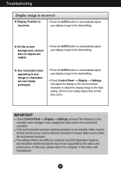
... image to the recommend resolution. If yes, readjust the video card to the ideal setting. G Any horizontal noise appearing in any image or characters are visible. • Press the AUTO button to automatically adjust your display image to the ideal setting. • Check Control Panel --> Display --> Settings and adjust the display to the recommended resolution or adjust the display image to the ideal setting. IMPORTANT Check Control Panel --> Display --> Settings and see if the frequency or the resolution were changed. Troubleshooting Display image is incorrect G Display Position...
... image to the recommend resolution. If yes, readjust the video card to the ideal setting. G Any horizontal noise appearing in any image or characters are visible. • Press the AUTO button to automatically adjust your display image to the ideal setting. • Check Control Panel --> Display --> Settings and adjust the display to the recommended resolution or adjust the display image to the ideal setting. IMPORTANT Check Control Panel --> Display --> Settings and see if the frequency or the resolution were changed. Troubleshooting Display image is incorrect G Display Position...

Owner's Manual
Page 22
...; Make sure to install the display driver from the display driver CD (or diskette) that comes with your display. Settings. Or, you see an "Unrecognized monitor, Plug&Play (VESA DDC) monitor found" message? G The screen blinks. • Check if the screen is set to interlace mode and if yes, change it to fasten if necessary. • Make sure the video card is properly connected and use a screwdriver to the recommend resolution. Troubleshooting Display image is incorrect G The screen color is...
...; Make sure to install the display driver from the display driver CD (or diskette) that comes with your display. Settings. Or, you see an "Unrecognized monitor, Plug&Play (VESA DDC) monitor found" message? G The screen blinks. • Check if the screen is set to interlace mode and if yes, change it to fasten if necessary. • Make sure the video card is properly connected and use a screwdriver to the recommend resolution. Troubleshooting Display image is incorrect G The screen color is...

Owner's Manual
Page 23
Digital Video Input Signal Input Input Form 15 pin D-Sub Connector DVI-D Connector (Digital) RGB Analog (0.7 Vp-p/ 75 ohm), Digital Resolution Plug&Play Max Recommend VESA 1920 x 1080 @ 60 Hz VESA 1920 x 1080 @ 60 Hz DDC 2B(Analog,Digital) Power Consumption On Mode Sleep Mode Off Mode : 24 W(Typ.) < 0.3 W < 0.3 W Dimensions & Weight With Stand Width 50.9 cm ( 19.80 inch ) Height 38.8 cm ( 15.27 inch ) Depth 16.6 cm ( 6.54 inch ) Without Stand Width 50.9 cm ( 19.80 inch ) Height 32.2 cm ( 12.67...
Digital Video Input Signal Input Input Form 15 pin D-Sub Connector DVI-D Connector (Digital) RGB Analog (0.7 Vp-p/ 75 ohm), Digital Resolution Plug&Play Max Recommend VESA 1920 x 1080 @ 60 Hz VESA 1920 x 1080 @ 60 Hz DDC 2B(Analog,Digital) Power Consumption On Mode Sleep Mode Off Mode : 24 W(Typ.) < 0.3 W < 0.3 W Dimensions & Weight With Stand Width 50.9 cm ( 19.80 inch ) Height 38.8 cm ( 15.27 inch ) Depth 16.6 cm ( 6.54 inch ) Without Stand Width 50.9 cm ( 19.80 inch ) Height 32.2 cm ( 12.67...

Owner's Manual
Page 24
...) Separate Sync. Digital Video Input Signal Input Input Form 15 pin D-Sub Connector DVI-D Connector (Digital) RGB Analog (0.7 Vp-p/ 75 ohm), Digital Resolution Plug&Play Max Recommend VESA 1920 x 1080 @ 60 Hz VESA 1920 x 1080 @ 60 Hz DDC 2B(Analog,Digital) Power Consumption On Mode Sleep Mode Off Mode : 28 W(Typ.) < 0.3 W < 0.3 W Dimensions & Weight With Stand Width 54.6 cm ( 21.49 inch ) Height 40.7 cm ( 16.02 inch ) Depth 20.2 cm ( 7.95 inch ) Without Stand Width 54.6 cm ( 21.49 inch ) Height 34.2 cm...
...) Separate Sync. Digital Video Input Signal Input Input Form 15 pin D-Sub Connector DVI-D Connector (Digital) RGB Analog (0.7 Vp-p/ 75 ohm), Digital Resolution Plug&Play Max Recommend VESA 1920 x 1080 @ 60 Hz VESA 1920 x 1080 @ 60 Hz DDC 2B(Analog,Digital) Power Consumption On Mode Sleep Mode Off Mode : 28 W(Typ.) < 0.3 W < 0.3 W Dimensions & Weight With Stand Width 54.6 cm ( 21.49 inch ) Height 40.7 cm ( 16.02 inch ) Depth 20.2 cm ( 7.95 inch ) Without Stand Width 54.6 cm ( 21.49 inch ) Height 34.2 cm...

Owner's Manual
Page 25
Specifications Preset Modes (Resolution) EW224T/EW234T Display Modes (Resolution) Horizontal Freq. (kHz) 1 720 x 400 2 640 x 480 3 640 x 480 4 800 x 600 5 800 x 600 6 1024 x 768 7 1024 x 768 8 1152 x 864 9 1280 x 1024 10 1280 x 1024 11 1680 x 1050 *12 1920 x 1080 31.468 31.469 37.500 37.879 46.875 48.363 60.123 67.500 63.981 79.976 65.290 67.500 Vertical Freq. (Hz) Polarity(H/V) 70 -/+ 60 -/- 75 -/- 60 +/+ 75 +/+ 60 -/- 75 +/+ 75 +/+ 60 +/+ 75 +/+ 60 -/+ 60 +/+ *Recommend Mode Indicator MODE On Mode Sleep Mode Off Mode LED Color Blue Blue Blinking Off 24
Specifications Preset Modes (Resolution) EW224T/EW234T Display Modes (Resolution) Horizontal Freq. (kHz) 1 720 x 400 2 640 x 480 3 640 x 480 4 800 x 600 5 800 x 600 6 1024 x 768 7 1024 x 768 8 1152 x 864 9 1280 x 1024 10 1280 x 1024 11 1680 x 1050 *12 1920 x 1080 31.468 31.469 37.500 37.879 46.875 48.363 60.123 67.500 63.981 79.976 65.290 67.500 Vertical Freq. (Hz) Polarity(H/V) 70 -/+ 60 -/- 75 -/- 60 +/+ 75 +/+ 60 -/- 75 +/+ 75 +/+ 60 +/+ 75 +/+ 60 -/+ 60 +/+ *Recommend Mode Indicator MODE On Mode Sleep Mode Off Mode LED Color Blue Blue Blinking Off 24

Owner's Manual
Page 27
... - Please refer to a locking cable that can be purchased separately at most computer stores. Kensington Security Slot Connected to the installation guide for more details, which is provided when Wall mount plate is connectable with respect to screw mounting interface dimensions and mounting screw specifications Please use VESA standard wall mount pad and screws. 26 Screw : 4.0 mm x Pitch 0.7 mm x Length 10 mm * 787.4 mm and above (31.0 inch) - Hole spacing...
... - Please refer to a locking cable that can be purchased separately at most computer stores. Kensington Security Slot Connected to the installation guide for more details, which is provided when Wall mount plate is connectable with respect to screw mounting interface dimensions and mounting screw specifications Please use VESA standard wall mount pad and screws. 26 Screw : 4.0 mm x Pitch 0.7 mm x Length 10 mm * 787.4 mm and above (31.0 inch) - Hole spacing...


