Owner's Manual (English)
Page 1
Environmental Protection Agency(EPA). LCD TV PLASMA TV OWNER'S MANUAL LCD TV MODELS 37LB5D 42LB5D 47LB5D 52LB5D 47LC7DF PLASMA TV MODELS 50PY3D 50PY3DF 60PY3D 60PY3DF Please read this information to your set . As an ENERGY STAR Partner LGE U. See the label attached on the ... require service. Retain it for energy efficiency. Record model number and serial number of power-saving guidelines issued by the U.S. www.lgusa.com / www.lg.ca has determined that this product meets the ENERGY STAR guidelines for future reference. S. A.,Inc. ENERGY STAR is a set of the set .
Environmental Protection Agency(EPA). LCD TV PLASMA TV OWNER'S MANUAL LCD TV MODELS 37LB5D 42LB5D 47LB5D 52LB5D 47LC7DF PLASMA TV MODELS 50PY3D 50PY3DF 60PY3D 60PY3DF Please read this information to your set . As an ENERGY STAR Partner LGE U. See the label attached on the ... require service. Retain it for energy efficiency. Record model number and serial number of power-saving guidelines issued by the U.S. www.lgusa.com / www.lg.ca has determined that this product meets the ENERGY STAR guidelines for future reference. S. A.,Inc. ENERGY STAR is a set of the set .
Owner's Manual (English)
Page 3
... the equipment and receiver. - Any changes or modifications not expressly approved by turning the equipment off and on a circuit different from LG Electronics. WARNING / CAUTION TO REDUCE THE RISK OF ELECTRIC SHOCK DO NOT REMOVE COVER (OR BACK). These limits are designed to ...to Article 820-40 of important operating and maintenance (servicing) instructions in a particular installation. Consult the dealer or an experienced radio/TV technician for compliance could void the user's authority to Part 15 of uninsulated "dangerous voltage" within an equilateral triangle is encouraged to...
... the equipment and receiver. - Any changes or modifications not expressly approved by turning the equipment off and on a circuit different from LG Electronics. WARNING / CAUTION TO REDUCE THE RISK OF ELECTRIC SHOCK DO NOT REMOVE COVER (OR BACK). These limits are designed to ...to Article 820-40 of important operating and maintenance (servicing) instructions in a particular installation. Consult the dealer or an experienced radio/TV technician for compliance could void the user's authority to Part 15 of uninsulated "dangerous voltage" within an equilateral triangle is encouraged to...

Owner's Manual (English)
Page 6
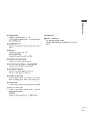
... 70 Audio Language 71 On-Screen Menus Language Selection 72 Caption Mode 73 - CONTENTS WARNING / CAUTION 1 SAFETY INSTRUCTIONS 2 FEATURE OF THIS TV 6 PREPARATION Accessories 7 Front Panel Information 8 Back Panel Information 10 Stand Installation 12 Not using the desk-type stand 13 Swivel Stand 13... Functions 34 Turning On TV 36 Channel Selection 36 Volume Adjustment 36 On-Screen Menus Selection 37 Channel Setup - Channel Editing 40 Input List 41 SimpLink 42 4 Input Label 44 Key Lock 45 MEDIAHOST MEDIAHOST Entry Modes 46 Photo List 47 Music List 51 PICTURE CONTROL...
... 70 Audio Language 71 On-Screen Menus Language Selection 72 Caption Mode 73 - CONTENTS WARNING / CAUTION 1 SAFETY INSTRUCTIONS 2 FEATURE OF THIS TV 6 PREPARATION Accessories 7 Front Panel Information 8 Back Panel Information 10 Stand Installation 12 Not using the desk-type stand 13 Swivel Stand 13... Functions 34 Turning On TV 36 Channel Selection 36 Volume Adjustment 36 On-Screen Menus Selection 37 Channel Setup - Channel Editing 40 Input List 41 SimpLink 42 4 Input Label 44 Key Lock 45 MEDIAHOST MEDIAHOST Entry Modes 46 Photo List 47 Music List 51 PICTURE CONTROL...

Owner's Manual (English)
Page 7
TIME SETTING Clock Setting - Auto Clock Setup 77 Manual Clock Setup 78 Auto On/Off Time Setting 79 Sleep Time Setting 80 Auto Shut-off Setting 81 PARENTAL CONTROL / RATINGS Set Password & Lock System 82 Channel Blocking 84 External Input Blocking 84 Movie & TV Rating 85 APPENDIX Troubleshooting 88 Maintenance 90 Product Specifications 91 Programming the Remote Control 93 IR Codes 97 External Control Through RS-232C 99 Open Source License 106 5
TIME SETTING Clock Setting - Auto Clock Setup 77 Manual Clock Setup 78 Auto On/Off Time Setting 79 Sleep Time Setting 80 Auto Shut-off Setting 81 PARENTAL CONTROL / RATINGS Set Password & Lock System 82 Channel Blocking 84 External Input Blocking 84 Movie & TV Rating 85 APPENDIX Troubleshooting 88 Maintenance 90 Product Specifications 91 Programming the Remote Control 93 IR Codes 97 External Control Through RS-232C 99 Open Source License 106 5
Owner's Manual (English)
Page 8
..." when it for long periods of this product with one remote control. LG TV with TV. It has three HDMI ports that adjusts the picture to the HDMI (high-definition multimedia interface), LG TV with this logo works easily with one cable and produces the highest quality ...digital images and sound. Manufactured under license from Dolby Laboratories. FOR LCD TV I Avoid touching the LCD screen or holding your local authority. 6 Disposal...
..." when it for long periods of this product with one remote control. LG TV with TV. It has three HDMI ports that adjusts the picture to the HDMI (high-definition multimedia interface), LG TV with this logo works easily with one cable and produces the highest quality ...digital images and sound. Manufactured under license from Dolby Laboratories. FOR LCD TV I Avoid touching the LCD screen or holding your local authority. 6 Disposal...

Owner's Manual (English)
Page 9
... that the following accessories are included with (Refer to p.16) the twist holder. 4-Bolts for stand assembly (Refer to p.12) For Plasma TV models For 50PY3D/F (This feature is not available for the product. Please be different from the figures MENU ENTER shown here. D-sub 15 pin... Cable For LCD TV models This feature is stain or fingerprint on the exterior only with ferrite cores to maintain standard compliance for all models For 37LB5D Cable ...
... that the following accessories are included with (Refer to p.16) the twist holder. 4-Bolts for stand assembly (Refer to p.12) For Plasma TV models For 50PY3D/F (This feature is not available for the product. Please be different from the figures MENU ENTER shown here. D-sub 15 pin... Cable For LCD TV models This feature is stain or fingerprint on the exterior only with ferrite cores to maintain standard compliance for all models For 37LB5D Cable ...

Owner's Manual (English)
Page 10
PREPARATION FRONT PANEL INFORMATION I NOTE: If your TV. Plasma TV Model PREPARATION Remote Control Sensor Program Display . . Power/Standby Indicator Illuminates red in standby mode. Touch Pad ENTER INPUT Button ENTER VOLUME Button (F,G) Buttons POWER Button MENU Button CHANNEL (E,D) Buttons 8 And then wipe the product with your product, use it). Illuminates white when the set is included with a cloth (If a polishing cloth is switched on. I Here shown may be somewhat different from your product has a protection tape attached, remove the tape.
PREPARATION FRONT PANEL INFORMATION I NOTE: If your TV. Plasma TV Model PREPARATION Remote Control Sensor Program Display . . Power/Standby Indicator Illuminates red in standby mode. Touch Pad ENTER INPUT Button ENTER VOLUME Button (F,G) Buttons POWER Button MENU Button CHANNEL (E,D) Buttons 8 And then wipe the product with your product, use it). Illuminates white when the set is included with a cloth (If a polishing cloth is switched on. I Here shown may be somewhat different from your product has a protection tape attached, remove the tape.

Owner's Manual (English)
Page 11
PREPARATION LCD TV Model 37/42/47/52LB5D 1 47LC7DF 1 2 3 CH CHANNEL (D,E)Buttons VOL VOLUME (F,G)Buttons ENTER MENU INPUT /I ENTER Button MENU Button INPUT Button POWER Button 2 3 1 Intelligent Eye Adjusts picture according to the surrounding conditions. 2 Remote Control Sensor 3 Power/Standby Indicator Illuminates red in standby mode. Illuminates green when the set is switched on. 9
PREPARATION LCD TV Model 37/42/47/52LB5D 1 47LC7DF 1 2 3 CH CHANNEL (D,E)Buttons VOL VOLUME (F,G)Buttons ENTER MENU INPUT /I ENTER Button MENU Button INPUT Button POWER Button 2 3 1 Intelligent Eye Adjusts picture according to the surrounding conditions. 2 Remote Control Sensor 3 Power/Standby Indicator Illuminates red in standby mode. Illuminates green when the set is switched on. 9
Owner's Manual (English)
Page 13
AUDIO (RGB/DVI) Connect the audio from a PC. Caution: Never attempt to operate the TV on a PC. 6 ANTENNA/CABLE IN Connect over-the air signals to this jack. 7 DIGITAL AUDIO OUT Connect digital audio to these jacks. S-VIDEO Connect S-Video ...
AUDIO (RGB/DVI) Connect the audio from a PC. Caution: Never attempt to operate the TV on a PC. 6 ANTENNA/CABLE IN Connect over-the air signals to this jack. 7 DIGITAL AUDIO OUT Connect digital audio to these jacks. S-VIDEO Connect S-Video ...

Owner's Manual (English)
Page 14
PREPARATION PREPARATION STAND INSTALLATION (Only 37LB5D) I Here shown may be somewhat different from your TV. 1 Carefully place the product screen side down on a cushioned surface that will protect product and screen from damage. 2 Assemble the product stand with the product as shown. 3 Securely install the 4 bolts provided. 12
PREPARATION PREPARATION STAND INSTALLATION (Only 37LB5D) I Here shown may be somewhat different from your TV. 1 Carefully place the product screen side down on a cushioned surface that will protect product and screen from damage. 2 Assemble the product stand with the product as shown. 3 Securely install the 4 bolts provided. 12

Owner's Manual (English)
Page 15
... the desk-type stand fixture protection cover(additional cover) by 20 degrees to suit your viewing position. ! ADDITIONAL COVER SWIVEL STAND (For Plasma TV) After installing the TV, you must close (to the right) the shaft bolt to set manually to the left or right direction by using the desk-type stand... not using the supplied bolts as shown at the figure. NOTE G Before adjusting the angle, you can adjust the the TV set the hole. 13 And when stand be level with TV, you must remove the cable management and loosen (to the left ) the shaft bolt on the middle of stand's back...
... the desk-type stand fixture protection cover(additional cover) by 20 degrees to suit your viewing position. ! ADDITIONAL COVER SWIVEL STAND (For Plasma TV) After installing the TV, you must close (to the right) the shaft bolt to set manually to the left or right direction by using the desk-type stand... not using the supplied bolts as shown at the figure. NOTE G Before adjusting the angle, you can adjust the the TV set the hole. 13 And when stand be level with TV, you must remove the cable management and loosen (to the left ) the shaft bolt on the middle of stand's back...

Owner's Manual (English)
Page 16
To connect an additional equipment, see the EXTERNAL EQUIPMENT SETUP section. 3 Install the CABLE MANAGEMENT as necessary. Plasma TV Model 1 Hold the CABLE MANAGEMENT with both hands and pull it backward as shown. 45° CABLE MANAGEMENT 2 Connect the cables as shown. 14 PREPARATION PREPARATION BACK COVER FOR WIRE ARRANGEMENT I Here shown may be somewhat different from your TV.
To connect an additional equipment, see the EXTERNAL EQUIPMENT SETUP section. 3 Install the CABLE MANAGEMENT as necessary. Plasma TV Model 1 Hold the CABLE MANAGEMENT with both hands and pull it backward as shown. 45° CABLE MANAGEMENT 2 Connect the cables as shown. 14 PREPARATION PREPARATION BACK COVER FOR WIRE ARRANGEMENT I Here shown may be somewhat different from your TV.

Owner's Manual (English)
Page 17
If the product is not available for all models.) CABLE MANAGEMENT ! To connect an additional equipment, see the EXTERNAL EQUIPMENT SETUP section. 2 Install the CABLE MANAGEMENT as necessary. TWISTER HOLDER How to remove the CABLE MANAGEMENT G Hold the CABLE MANAGEMENT with both hands and pull it backward. 15 PREPARATION LCD TV Model 1 Connect the cables as shown. 3 Bundle the cables using the supplied TWISTER HOLDER. (This feature is dropped, you may be injured or the product may be broken. NOTE G Do not hold the CABLE MANAGEMENT when moving the product. -
If the product is not available for all models.) CABLE MANAGEMENT ! To connect an additional equipment, see the EXTERNAL EQUIPMENT SETUP section. 2 Install the CABLE MANAGEMENT as necessary. TWISTER HOLDER How to remove the CABLE MANAGEMENT G Hold the CABLE MANAGEMENT with both hands and pull it backward. 15 PREPARATION LCD TV Model 1 Connect the cables as shown. 3 Bundle the cables using the supplied TWISTER HOLDER. (This feature is dropped, you may be injured or the product may be broken. NOTE G Do not hold the CABLE MANAGEMENT when moving the product. -

Owner's Manual (English)
Page 18
... wall so it cannot be somewhat different from the TV. Ensure the eye-bolts or brackets are tightened securely. Plasma TV Model 50PY3D/F 60PY3D/F LCD TV Model I Use a sturdy rope (not provided as parts of the bracket that you set up the TV close to the wall. Secure the wall brackets with ...for all models. Additionally, we recommend that children don't climb on the wall to the wall as shown in the picture. * If your TV. Match the height of the product, must purchase separately) to tie the rope so it cannot fall over if pushed backwards. PREPARATION PREPARATION ...
... wall so it cannot be somewhat different from the TV. Ensure the eye-bolts or brackets are tightened securely. Plasma TV Model 50PY3D/F 60PY3D/F LCD TV Model I Use a sturdy rope (not provided as parts of the bracket that you set up the TV close to the wall. Secure the wall brackets with ...for all models. Additionally, we recommend that children don't climb on the wall to the wall as shown in the picture. * If your TV. Match the height of the product, must purchase separately) to tie the rope so it cannot fall over if pushed backwards. PREPARATION PREPARATION ...

Owner's Manual (English)
Page 19
... mm LCD TV Model 600 mm (47LB5D, 47LC7DF, 52LB5D: 800 mm) AV IN 2 USB S-VIDEO 400 mm 400 mm VIDEO L/MONO AUDIO R ! For further information, refer to the VESA Wall Mounting Instruction Guide. 17 PREPARATION DESKTOP PEDESTAL INSTALLATION For proper ventilation, allow a clearance of 4 inches on the wall mount used. Plasma TV Model LCD TV Model...
... mm LCD TV Model 600 mm (47LB5D, 47LC7DF, 52LB5D: 800 mm) AV IN 2 USB S-VIDEO 400 mm 400 mm VIDEO L/MONO AUDIO R ! For further information, refer to the VESA Wall Mounting Instruction Guide. 17 PREPARATION DESKTOP PEDESTAL INSTALLATION For proper ventilation, allow a clearance of 4 inches on the wall mount used. Plasma TV Model LCD TV Model...

Owner's Manual (English)
Page 20
...RF Coaxial Wire (75 ohm) ( ) Antenna UHF Signal Amplifier VHF ANTENNA/ CABLE IN I If the antenna is not installed properly, contact your TV. 1. PREPARATION PREPARATION ANTENNA OR CABLE CONNECTION I Here shown may be split for assistance. ( ) ! I If the antenna needs to wall ...Outdoor Antenna (VHF, UHF) 2. Wall Antenna Socket Multi-family Dwellings/Apartments (Connect to be somewhat different from your dealer for two TV's, install a 2-Way Signal Splitter. For optimum picture quality, adjust antenna direction if needed. Antenna (Analog or Digital) Wall Antenna ...
...RF Coaxial Wire (75 ohm) ( ) Antenna UHF Signal Amplifier VHF ANTENNA/ CABLE IN I If the antenna is not installed properly, contact your TV. 1. PREPARATION PREPARATION ANTENNA OR CABLE CONNECTION I Here shown may be split for assistance. ( ) ! I If the antenna needs to wall ...Outdoor Antenna (VHF, UHF) 2. Wall Antenna Socket Multi-family Dwellings/Apartments (Connect to be somewhat different from your dealer for two TV's, install a 2-Way Signal Splitter. For optimum picture quality, adjust antenna direction if needed. Antenna (Analog or Digital) Wall Antenna ...
Owner's Manual (English)
Page 21
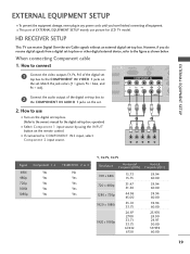
...720 x 480i 720 x 480p 1280 x 720p 1920 x 1080i 1920 x 1080p 15.73 15.73 31.47 31.50 44.96 45.00 33.72 33.75 26.97 27.00 33.71 33.75 67.432...I Select Component 1 input source by using the INPUT button on the remote control. HD RECEIVER SETUP This TV can receive Digital Over-the-air/Cable signals without an external digital set . I To prevent the equipment damage...device, refer to the COMPONENT IN AUDIO 1 jacks on the set -top box. (Refer to the owner's manual for LCD TV model. How to connect I If connected to the COMPONENT IN VIDEO 1 jacks on the digital set . Match the jack...
...720 x 480i 720 x 480p 1280 x 720p 1920 x 1080i 1920 x 1080p 15.73 15.73 31.47 31.50 44.96 45.00 33.72 33.75 26.97 27.00 33.71 33.75 67.432...I Select Component 1 input source by using the INPUT button on the remote control. HD RECEIVER SETUP This TV can receive Digital Over-the-air/Cable signals without an external digital set . I To prevent the equipment damage...device, refer to the COMPONENT IN AUDIO 1 jacks on the set -top box. (Refer to the owner's manual for LCD TV model. How to connect I If connected to the COMPONENT IN VIDEO 1 jacks on the digital set . Match the jack...

Owner's Manual (English)
Page 24
Component ports on the TV Y PB PR Video output ports on the DVD player, insert a DVD. RGB IN Match the jack colors (Y = green, PB = blue, and PR = red). I Select Component 1 ...
Component ports on the TV Y PB PR Video output ports on the DVD player, insert a DVD. RGB IN Match the jack colors (Y = green, PB = blue, and PR = red). I Select Component 1 ...
Owner's Manual (English)
Page 26
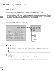
...to the VCR owner's manual.) 24 ( ) How to use I To avoid picture noise (interference), leave an adequate distance between the VCR and TV. I Use the ISM feature in consequence the manufactures warranty does no( t )cover the product bearing this phenomenon. This phenomenon is used; When connecting... SWITCH Wall Jack 2 Antenna 1. EXTERNAL EQUIPMENT SETUP EXTERNAL EQUIPMENT SETUP VCR SETUP I Set VCR output switch to 3 or 4 and then tune TV to the same channel number. If the 4:3 picture format is common to all manufactures and in the Option menu to avoid having a fixed image...
...to the VCR owner's manual.) 24 ( ) How to use I To avoid picture noise (interference), leave an adequate distance between the VCR and TV. I Use the ISM feature in consequence the manufactures warranty does no( t )cover the product bearing this phenomenon. This phenomenon is used; When connecting... SWITCH Wall Jack 2 Antenna 1. EXTERNAL EQUIPMENT SETUP EXTERNAL EQUIPMENT SETUP VCR SETUP I Set VCR output switch to 3 or 4 and then tune TV to the same channel number. If the 4:3 picture format is common to all manufactures and in the Option menu to avoid having a fixed image...
Owner's Manual (English)
Page 27
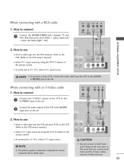
... have a mono VCR, connect the audio cable from the VCR to the VCR owner's manual.) I If connected to connect 1 Connect the AUDIO/VIDEO jacks between TV and VCR. How to use T IN I If connected to the S -VIDEO input on the remote control. UDIO B/DVI) 2. AUDIO S-VIDEO VIDEO (MONO) AUDIO I Insert a video...
... have a mono VCR, connect the audio cable from the VCR to the VCR owner's manual.) I If connected to connect 1 Connect the AUDIO/VIDEO jacks between TV and VCR. How to use T IN I If connected to the S -VIDEO input on the remote control. UDIO B/DVI) 2. AUDIO S-VIDEO VIDEO (MONO) AUDIO I Insert a video...


