Owner's Manual (English)
Page 3
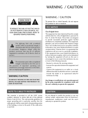
... harmful interference to provide reasonable protection against harmful interference in a particular installation. REFER TO QUALIFIED SERVICE PERSONNEL. NOTE TO CABLE/TV INSTALLER This reminder is provided to call the CATV system installer's attention to radio or television reception, which the receiver is intended to alert the user to operate the equipment. CAUTION Do not attempt to modify this equipment does...
... harmful interference to provide reasonable protection against harmful interference in a particular installation. REFER TO QUALIFIED SERVICE PERSONNEL. NOTE TO CABLE/TV INSTALLER This reminder is provided to call the CATV system installer's attention to radio or television reception, which the receiver is intended to alert the user to operate the equipment. CAUTION Do not attempt to modify this equipment does...

Owner's Manual (English)
Page 6
... VESA Wall Mounting 17 Antenna or Cable Connection 18 EXTERNAL EQUIPMENT SETUP HD Receiver Setup 19 DVD Setup 22 VCR Setup 24 Other A/V Source Setup 26 PC Setup 27 USB In Setup 32 Audio Out Setup 33 WATCHING TV / CHANNEL CONTROL Remote Control Functions 34 Turning On TV 36 Channel Selection 36 Volume Adjustment 36 On-Screen Menus Selection 37 Channel Setup - User Mode 67 Balance 68 TV Speakers On/Off Setup 69 Stereo/SAP Broadcasts Setup 70 Audio Language 71 On-Screen Menus Language Selection 72 Caption Mode 73 - Black (Darkness) Level 60 Picture Reset...
... VESA Wall Mounting 17 Antenna or Cable Connection 18 EXTERNAL EQUIPMENT SETUP HD Receiver Setup 19 DVD Setup 22 VCR Setup 24 Other A/V Source Setup 26 PC Setup 27 USB In Setup 32 Audio Out Setup 33 WATCHING TV / CHANNEL CONTROL Remote Control Functions 34 Turning On TV 36 Channel Selection 36 Volume Adjustment 36 On-Screen Menus Selection 37 Channel Setup - User Mode 67 Balance 68 TV Speakers On/Off Setup 69 Stereo/SAP Broadcasts Setup 70 Audio Language 71 On-Screen Menus Language Selection 72 Caption Mode 73 - Black (Darkness) Level 60 Picture Reset...
Owner's Manual (English)
Page 8
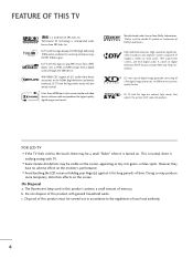
... not dispose of your finger(s) against it is turned on the monitor's performance. With HDMI CEC support of SRS Labs, Inc. FEATURE OF THIS TV is a trademark of LG's audio/video device connected to the HDMI (high-definition multimedia interface), LG TV with this logo works easily with one cable and produces the highest quality digital images and sound. However, they have no adverse effect on...
... not dispose of your finger(s) against it is turned on the monitor's performance. With HDMI CEC support of SRS Labs, Inc. FEATURE OF THIS TV is a trademark of LG's audio/video device connected to the HDMI (high-definition multimedia interface), LG TV with this logo works easily with one cable and produces the highest quality digital images and sound. However, they have no adverse effect on...
Owner's Manual (English)
Page 13
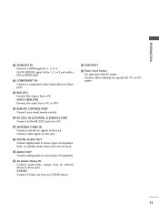
... (CONTROL & SERVICE) PORT Connect to the RS-232C port on DC power. 11 S-VIDEO Connect S-Video out from a PC. Connect cable signals to this jack. Note: In standby mode, these ports do not work. 8 AUDIO OUT Connect analog audio to this jack. 7 DIGITAL AUDIO OUT Connect digital audio to various types of equipment. 9 AV (Audio/Video) IN Connect audio/video output from an external device to these jacks. 3 RGB (PC) Connect the output from an S-VIDEO device. 10 USB INPUT 11 Power Cord Socket For operation with a DVI to HDMI cable. 2 COMPONENT IN Connect a component video/audio device...
... (CONTROL & SERVICE) PORT Connect to the RS-232C port on DC power. 11 S-VIDEO Connect S-Video out from a PC. Connect cable signals to this jack. Note: In standby mode, these ports do not work. 8 AUDIO OUT Connect analog audio to this jack. 7 DIGITAL AUDIO OUT Connect digital audio to various types of equipment. 9 AV (Audio/Video) IN Connect audio/video output from an external device to these jacks. 3 RGB (PC) Connect the output from an S-VIDEO device. 10 USB INPUT 11 Power Cord Socket For operation with a DVI to HDMI cable. 2 COMPONENT IN Connect a component video/audio device...

Owner's Manual (English)
Page 19
... G Screw length needed depends on all four sides from the wall. Plasma TV Model 600 mm LCD TV Model 600 mm (47LB5D, 47LC7DF, 52LB5D: 800 mm) AV IN 2 USB S-VIDEO 400 mm 400 mm VIDEO L/MONO AUDIO R ! VESA WALL MOUNTING This product accepts a VESA-compliant mounting interface pad. (optional) There 4 threaded holes are available for attaching the bracket. PREPARATION DESKTOP PEDESTAL INSTALLATION For proper ventilation, allow a clearance of 4 inches on the wall mount used...
... G Screw length needed depends on all four sides from the wall. Plasma TV Model 600 mm LCD TV Model 600 mm (47LB5D, 47LC7DF, 52LB5D: 800 mm) AV IN 2 USB S-VIDEO 400 mm 400 mm VIDEO L/MONO AUDIO R ! VESA WALL MOUNTING This product accepts a VESA-compliant mounting interface pad. (optional) There 4 threaded holes are available for attaching the bracket. PREPARATION DESKTOP PEDESTAL INSTALLATION For proper ventilation, allow a clearance of 4 inches on the wall mount used...
Owner's Manual (English)
Page 21
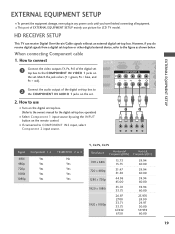
... shown below. When connecting Component cable 1. operation) I Select Component 1 input source by using the INPUT button on the set top box to the COMPONENT IN VIDEO 1 jacks on the remote control. I To prevent the equipment damage, never plug in any power cords until you do receive digital signals from a digital set -top box. How to connect I Turn on the set -top box. How to use picture for the digital set . Match the jack colors (Y = green, PB = blue, and PR = red). 2 Connect the audio output of the digital set . However, if you...
... shown below. When connecting Component cable 1. operation) I Select Component 1 input source by using the INPUT button on the set top box to the COMPONENT IN VIDEO 1 jacks on the remote control. I To prevent the equipment damage, never plug in any power cords until you do receive digital signals from a digital set -top box. How to connect I Turn on the set -top box. How to use picture for the digital set . Match the jack colors (Y = green, PB = blue, and PR = red). 2 Connect the audio output of the digital set . However, if you...

Owner's Manual (English)
Page 22
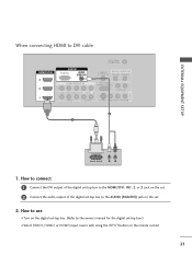
....75 30.00 67.432 59.939 67.50 60.00 20 How to connect 1 Connect the digital set-top box to the owner's manual for the digital set-top box.) I Select HDMI1, HDMI2 or HDMI3 input source with using the INPUT button on the set -top box. (Refer to HDMI/DVI IN1, 2 or 3 jack on the remote control. How to use I Turn on the digital set . 2 No separated audio connection is necessary. EXTERNAL EQUIPMENT SETUP EXTERNAL EQUIPMENT SETUP When connecting HDMI cable 1.
....75 30.00 67.432 59.939 67.50 60.00 20 How to connect 1 Connect the digital set-top box to the owner's manual for the digital set-top box.) I Select HDMI1, HDMI2 or HDMI3 input source with using the INPUT button on the set -top box. (Refer to HDMI/DVI IN1, 2 or 3 jack on the remote control. How to use I Turn on the digital set . 2 No separated audio connection is necessary. EXTERNAL EQUIPMENT SETUP EXTERNAL EQUIPMENT SETUP When connecting HDMI cable 1.
Owner's Manual (English)
Page 23
... HDMI3 input source with using the INPUT button on the digital set-top box. (Refer to the owner's manual for the digital set . 2. How to connect 1 Connect the DVI output of the digital set-top box to the HDMI/DVI IN1, 2 or 3 jack on the set. 2 Connect the audio output of the digital set-top box to DVI cable HDMI/DVI IN 3 2 RGB IN RGB(PC) AUDIO (RGB/DVI) COMPONENT IN 2 1 1 VIDEO AUDIO ANTENNA/ CABLE IN REMOTE DIGITAL AUDIO OUT CONTROL IN OPTICAL COAXIAL RS-232C IN (CONTROL & SERVICE) AUDIO OUT S-VIDEO VIDEO (MONO) AUDIO...
... HDMI3 input source with using the INPUT button on the digital set-top box. (Refer to the owner's manual for the digital set . 2. How to connect 1 Connect the DVI output of the digital set-top box to the HDMI/DVI IN1, 2 or 3 jack on the set. 2 Connect the audio output of the digital set-top box to DVI cable HDMI/DVI IN 3 2 RGB IN RGB(PC) AUDIO (RGB/DVI) COMPONENT IN 2 1 1 VIDEO AUDIO ANTENNA/ CABLE IN REMOTE DIGITAL AUDIO OUT CONTROL IN OPTICAL COAXIAL RS-232C IN (CONTROL & SERVICE) AUDIO OUT S-VIDEO VIDEO (MONO) AUDIO...

Owner's Manual (English)
Page 24
... connect a DVD player to use I If connected to the DVD player's manual for operating instructions. RGB IN Match the jack colors (Y = green, PB = blue, and PR = red). How to the component input ports as shown below. I Turn on the remote control. Component ports on the TV Y PB PR Video output ports on the set . 2. I Select Component 1 input source by using the INPUT button on the DVD player, insert a DVD. I Refer to COMPONENT IN 2 input, select Component 2 input source. EXTERNAL EQUIPMENT SETUP EXTERNAL EQUIPMENT SETUP DVD SETUP When connecting Component cable...
... connect a DVD player to use I If connected to the DVD player's manual for operating instructions. RGB IN Match the jack colors (Y = green, PB = blue, and PR = red). How to the component input ports as shown below. I Turn on the remote control. Component ports on the TV Y PB PR Video output ports on the set . 2. I Select Component 1 input source by using the INPUT button on the DVD player, insert a DVD. I Refer to COMPONENT IN 2 input, select Component 2 input source. EXTERNAL EQUIPMENT SETUP EXTERNAL EQUIPMENT SETUP DVD SETUP When connecting Component cable...
Owner's Manual (English)
Page 25
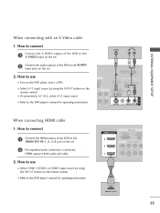
.../DVI COMPONENT IN 2 1 1 VIDEO A 1 HDMI-DVD OUTPUT 23 I If connected to the DVD player's manual for operating instructions. I Turn on the set . 2 Connect the audio outputs of the DVD to the S -VIDEO input on the set . 2. EXTERNAL EQUIPMENT SETUP When connecting with an S-Video cable 1. S-VIDEO AUDIO L R UDIO B/DVI) T IN ANTENNA/ CABLE IN 1 2 REMOTE DIGITAL AUDIO OUT CONTROL IN OPTICAL COAXIAL RS-232C IN (CONTROL & SERVICE) AUDIO OUT AUDIO S-VIDEO VIDEO (MONO) AUDIO AV IN 1 When connecting HDMI cable 1. How to use I Refer to the AUDIO input jacks...
.../DVI COMPONENT IN 2 1 1 VIDEO A 1 HDMI-DVD OUTPUT 23 I If connected to the DVD player's manual for operating instructions. I Turn on the set . 2 Connect the audio outputs of the DVD to the S -VIDEO input on the set . 2. EXTERNAL EQUIPMENT SETUP When connecting with an S-Video cable 1. S-VIDEO AUDIO L R UDIO B/DVI) T IN ANTENNA/ CABLE IN 1 2 REMOTE DIGITAL AUDIO OUT CONTROL IN OPTICAL COAXIAL RS-232C IN (CONTROL & SERVICE) AUDIO OUT AUDIO S-VIDEO VIDEO (MONO) AUDIO AV IN 1 When connecting HDMI cable 1. How to use I Refer to the AUDIO input jacks...
Owner's Manual (English)
Page 26
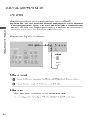
... to the ANTENNA/CABLE IN socket on the sides of time (Only Plasma TV model). If the 4:3 picture format is common to the VCR owner's manual.) 24 ( ) When connecting with an antenna GB IN AUDIO (RGB/DVI) MPONENT IN ANTENNA/ CABLE IN REMOTE DIGITAL AUDIO OUT CONTROL IN OPTICAL COAXIAL RS-232C IN (CONTROL & SERVICE) AUDIO OUT EO AUDIO S-VIDEO VIDEO (MONO) AUDIO AV IN 1 1 ANT OUT S-VIDEO VIDEO L R ANT IN OUTPUT SWITCH Wall Jack 2 Antenna 1. This phenomenon is used; I To avoid picture noise...
... to the ANTENNA/CABLE IN socket on the sides of time (Only Plasma TV model). If the 4:3 picture format is common to the VCR owner's manual.) 24 ( ) When connecting with an antenna GB IN AUDIO (RGB/DVI) MPONENT IN ANTENNA/ CABLE IN REMOTE DIGITAL AUDIO OUT CONTROL IN OPTICAL COAXIAL RS-232C IN (CONTROL & SERVICE) AUDIO OUT EO AUDIO S-VIDEO VIDEO (MONO) AUDIO AV IN 1 1 ANT OUT S-VIDEO VIDEO L R ANT IN OUTPUT SWITCH Wall Jack 2 Antenna 1. This phenomenon is used; I To avoid picture noise...
Owner's Manual (English)
Page 27
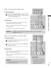
... VCR owner's manual.) ANTENNA/ CABLE IN 1 REMOTE CONTROL IN DIGITAL A2UDIO OUT OPTIC(AL )COAXIAL RS-232C IN (CONTROL & SERVICE) AUDIO OUT AV IN 1 I If connected to normal composite (RCA cable) input. I Select A V 1 input source by using the INPUT button on the VCR. (Refer to connect 1 Connect the AUDIO/VIDEO jacks between TV and VCR. UDIO B/DVI) 2. NOTE G The picture quality is improved: compared to AV IN2, select A V 2 input source. Match the jack colors (Video = yellow, Audio Left = white, and Audio Right = red...
... VCR owner's manual.) ANTENNA/ CABLE IN 1 REMOTE CONTROL IN DIGITAL A2UDIO OUT OPTIC(AL )COAXIAL RS-232C IN (CONTROL & SERVICE) AUDIO OUT AV IN 1 I If connected to normal composite (RCA cable) input. I Select A V 1 input source by using the INPUT button on the VCR. (Refer to connect 1 Connect the AUDIO/VIDEO jacks between TV and VCR. UDIO B/DVI) 2. NOTE G The picture quality is improved: compared to AV IN2, select A V 2 input source. Match the jack colors (Video = yellow, Audio Left = white, and Audio Right = red...
Owner's Manual (English)
Page 29
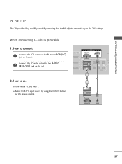
... use I Turn on the set . 1 VIDEO AUDIO ( ) 2. How to the RG B (P C) jack on the PC and the TV. EXTERNAL EQUIPMENT SETUP When connecting D-sub 15 pin cable 1. I Select RGB-PC input source by using the INPUT button on the set . PC SETUP This TV provides Plug and Play capability, meaning that the PC adjusts automatically to the AUDIO 2 2 (RGB/DVI) jack on the remote control. 1 2 RGB OUTPUT AUDIO ( 27 I /DVI IN RGB(PC) AUDIO (RGB/DVI) CO COMPONENT...
... use I Turn on the set . 1 VIDEO AUDIO ( ) 2. How to the RG B (P C) jack on the PC and the TV. EXTERNAL EQUIPMENT SETUP When connecting D-sub 15 pin cable 1. I Select RGB-PC input source by using the INPUT button on the set . PC SETUP This TV provides Plug and Play capability, meaning that the PC adjusts automatically to the AUDIO 2 2 (RGB/DVI) jack on the remote control. 1 2 RGB OUTPUT AUDIO ( 27 I /DVI IN RGB(PC) AUDIO (RGB/DVI) CO COMPONENT...

Owner's Manual (English)
Page 31
NOTE G Depending on the graphics card, DOS mode may not work if a HDMI to find best picture in a little time. 29 There may become permanently imprinted on your TV. EXTERNAL EQUIPMENT SETUP Supported Display Specifications RGB-PC, HDMI-PC Resolution Horizontal Vertical Frequency(KHz) Frequency(Hz) 640x350 31.468 70.09 720x400 31.469 70.08 640x480 31.469 37.500 37.861 59.94...
NOTE G Depending on the graphics card, DOS mode may not work if a HDMI to find best picture in a little time. 29 There may become permanently imprinted on your TV. EXTERNAL EQUIPMENT SETUP Supported Display Specifications RGB-PC, HDMI-PC Resolution Horizontal Vertical Frequency(KHz) Frequency(Hz) 640x350 31.468 70.09 720x400 31.469 70.08 640x480 31.469 37.500 37.861 59.94...
Owner's Manual (English)
Page 35
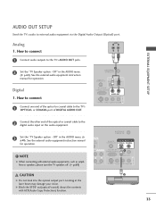
... external audio equipment instruction manual for operation. See the external audio equipment instruction manual for operation. ! Off " in the AUDIO menu. (G p.69). Digital 1. G Block the SPDIF out(optical/coaxial) about the contents with external audio equipments, such as amplifiers or speakers, please turn the TV speakers off. (G p.69) DIO DVI) IN ANTENNA/ CABLE IN REMOTE DIGITAL AUDIO OUT CONTROL IN OPTICAL COAXIAL RS-232C IN (CONTROL & SERVICE) 1 AUDIO OUT AUDIO S-VIDEO VIDEO (MONO) AUDIO AV IN 1 CAUTION G Do not look into the optical output port. NOTE G When connecting...
... external audio equipment instruction manual for operation. See the external audio equipment instruction manual for operation. ! Off " in the AUDIO menu. (G p.69). Digital 1. G Block the SPDIF out(optical/coaxial) about the contents with external audio equipments, such as amplifiers or speakers, please turn the TV speakers off. (G p.69) DIO DVI) IN ANTENNA/ CABLE IN REMOTE DIGITAL AUDIO OUT CONTROL IN OPTICAL COAXIAL RS-232C IN (CONTROL & SERVICE) 1 AUDIO OUT AUDIO S-VIDEO VIDEO (MONO) AUDIO AV IN 1 CAUTION G Do not look into the optical output port. NOTE G When connecting...

Owner's Manual (English)
Page 37
... CC Select the Caption On/Off. STB MEDIA HOST WATCHING TV / CHANNEL CONTROL POWER Turns your TV or any other programmed equipment on or off, depending on the viewing environment. G p.73 MARK Enter the selected functions. MEDIAHOST Inside the Sliding Cover BACK PICTURE SOUND SAP CC MARK USB EJECT PICTURE Adjust the factory preset picture depend on the mode. G p.46 Installing Batteries Remote control effective range I Close cover. LIVE TV INPUT MODE DAY - INPUT External input modes rotate in...
... CC Select the Caption On/Off. STB MEDIA HOST WATCHING TV / CHANNEL CONTROL POWER Turns your TV or any other programmed equipment on or off, depending on the viewing environment. G p.73 MARK Enter the selected functions. MEDIAHOST Inside the Sliding Cover BACK PICTURE SOUND SAP CC MARK USB EJECT PICTURE Adjust the factory preset picture depend on the mode. G p.46 Installing Batteries Remote control effective range I Close cover. LIVE TV INPUT MODE DAY - INPUT External input modes rotate in...
Owner's Manual (English)
Page 41
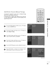
.... 1 Auto Tuning Manual Tuning Channel Edit G Select channel type and RF-channel number. Auto Tuning Manual Tuning Channel Edit BACK 2 Press the G button and then use D or E button to select channel you can view the on . TV INPUT TV INPUT Add/Delete Channel (Manual Tuning) STB MEDIA HOST STB MEDIA HOST A password is turned on -screen signal strength monitor to select the SETUP menu. DTV 2 5 Press the ENTER button to add or delete the channel. 6 Press EXIT button to return to TV viewing or press MENU button...
.... 1 Auto Tuning Manual Tuning Channel Edit G Select channel type and RF-channel number. Auto Tuning Manual Tuning Channel Edit BACK 2 Press the G button and then use D or E button to select channel you can view the on . TV INPUT TV INPUT Add/Delete Channel (Manual Tuning) STB MEDIA HOST STB MEDIA HOST A password is turned on -screen signal strength monitor to select the SETUP menu. DTV 2 5 Press the ENTER button to add or delete the channel. 6 Press EXIT button to return to TV viewing or press MENU button...

Owner's Manual (English)
Page 84
... use this menu. 1 Press the MENU button and then use the Movie Rating System (MPAA) only. Set ratings and categories to be used to be blocked by broadcasting stations. Specify a password 3. I TV-Y7 (Children 7 years older) PARENTAL CONTROL / RATING SET PASSWORD & LOCK SYSTEM Setting up Your Password Set up with the initial password "0-0-0-0". I The TV is required to gain access to block specific channels, ratings, and external viewing sources. Most television programs and television movies can be viewed. A password is set...
... use this menu. 1 Press the MENU button and then use the Movie Rating System (MPAA) only. Set ratings and categories to be used to be blocked by broadcasting stations. Specify a password 3. I TV-Y7 (Children 7 years older) PARENTAL CONTROL / RATING SET PASSWORD & LOCK SYSTEM Setting up Your Password Set up with the initial password "0-0-0-0". I The TV is required to gain access to block specific channels, ratings, and external viewing sources. Most television programs and television movies can be viewed. A password is set...
Owner's Manual (English)
Page 95
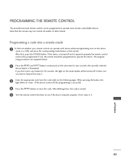
... same time for 20 seconds, the light on the mode button will be programmed to repeat from step 2. 3 Enter the appropriate code from the code table on the remote. Note that case, you don't press any button for two seconds; APPENDIX 93 After that, press the POWER button. Programming a code into a remote mode 1 To find out whether your remote control can be turned off. PROGRAMMING THE REMOTE CONTROL The provided universal remote control can operate each...
... same time for 20 seconds, the light on the mode button will be programmed to repeat from step 2. 3 Enter the appropriate code from the code table on the remote. Note that case, you don't press any button for two seconds; APPENDIX 93 After that, press the POWER button. Programming a code into a remote mode 1 To find out whether your remote control can be turned off. PROGRAMMING THE REMOTE CONTROL The provided universal remote control can operate each...
Owner's Manual (English)
Page 103
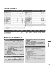
Input Select x 04. Volume Mute k 07. Tint k 12. Remote Control Lock Mode k a 0~1 15. Bass k b (G p.102) 17. Green Adjustment k f 0 ~ 64 21. Channel Add/Del m j 0 ~ 64 26. Transmit the 'FF' data to choose desired TV ID number in Setup menu. At this model, TV will not send the status during the standby mode. Command Reference List COMMAND1 COMMAND2 DATA (Hexadecimal) COMMAND1 COMMAND2 DATA (Hexadecimal) 01. Brightness k 10. OSD Select k 14. Balance...
Input Select x 04. Volume Mute k 07. Tint k 12. Remote Control Lock Mode k a 0~1 15. Bass k b (G p.102) 17. Green Adjustment k f 0 ~ 64 21. Channel Add/Del m j 0 ~ 64 26. Transmit the 'FF' data to choose desired TV ID number in Setup menu. At this model, TV will not send the status during the standby mode. Command Reference List COMMAND1 COMMAND2 DATA (Hexadecimal) COMMAND1 COMMAND2 DATA (Hexadecimal) 01. Brightness k 10. OSD Select k 14. Balance...


