Owner's Manual (English)
Page 1
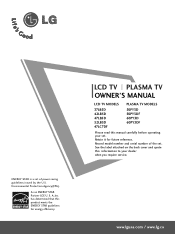
See the label attached on the back cover and quote this manual carefully before operating your dealer when you require service. www.lgusa.com / www.lg.ca A.,Inc. LCD TV PLASMA TV OWNER'S MANUAL LCD TV MODELS 37LB5D 42LB5D 47LB5D 52LB5D 47LC7DF PLASMA TV MODELS 50PY3D 50PY3DF 60PY3D 60PY3DF Please read this information to your set. S. Retain it for energy efficiency. Environmental...
See the label attached on the back cover and quote this manual carefully before operating your dealer when you require service. www.lgusa.com / www.lg.ca A.,Inc. LCD TV PLASMA TV OWNER'S MANUAL LCD TV MODELS 37LB5D 42LB5D 47LB5D 52LB5D 47LC7DF PLASMA TV MODELS 50PY3D 50PY3DF 60PY3D 60PY3DF Please read this information to your set. S. Retain it for energy efficiency. Environmental...

Owner's Manual (English)
Page 5
... outlets, extension cords, frayed power cords, or damaged or cracked wire insulation are not possible, have fallen into the product, and do not expose this owner's manual to dripping or splashing and no additional outlets or branch circuits. When a cart is required when the apparatus has been damaged in any objects to...
... outlets, extension cords, frayed power cords, or damaged or cracked wire insulation are not possible, have fallen into the product, and do not expose this owner's manual to dripping or splashing and no additional outlets or branch circuits. When a cart is required when the apparatus has been damaged in any objects to...

Owner's Manual (English)
Page 9
...Management 2- D-sub 15 pin Cable For LCD TV models This feature is stain or fingerprint on the exterior only with ferrite cores to p.16) 2- TV Bracket (Refer to p.13) Bolts (Refer to p.12) For Plasma TV models For 50PY3D/F (This feature is... + ENTER VCR STB INPUT TIMER EXIT Owner's Manual VOL MUTE 1 FAV 4 2 7 5 3 8 6 0 9 BACK RATIO SIMPLINK CH Owner's Manual Copyright© 2007 LGE, All Rights Reserved. Eye Bolts (Refer to p.16) (Refer to p.13) 7 Rubbers 2- RATIO SIMPLINK FAV CH TV INPUT TV AUDIO POWER CAMBLOEDDEVD BRIGHT - Wall Brackets ...
...Management 2- D-sub 15 pin Cable For LCD TV models This feature is stain or fingerprint on the exterior only with ferrite cores to p.16) 2- TV Bracket (Refer to p.13) Bolts (Refer to p.12) For Plasma TV models For 50PY3D/F (This feature is... + ENTER VCR STB INPUT TIMER EXIT Owner's Manual VOL MUTE 1 FAV 4 2 7 5 3 8 6 0 9 BACK RATIO SIMPLINK CH Owner's Manual Copyright© 2007 LGE, All Rights Reserved. Eye Bolts (Refer to p.16) (Refer to p.13) 7 Rubbers 2- RATIO SIMPLINK FAV CH TV INPUT TV AUDIO POWER CAMBLOEDDEVD BRIGHT - Wall Brackets ...
Owner's Manual (English)
Page 21
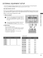
...x 480i 720 x 480p 1280 x 720p 1920 x 1080i 1920 x 1080p 15.73 15.73 31.47 31.50 44.96 45.00 33.72 33.75 26.97 27.00 33.71 33.75 67...00 59.939 60.00 19 I Turn on the digital set -top box. HD RECEIVER SETUP This TV can receive Digital Over-the-air/Cable signals without an external digital set . However, if you have finished...INPUT button on the remote control. How to connect I This part of EXTERNAL EQUIPMENT SETUP mainly use I If connected to the owner's manual for LCD TV model. COMPONENT IN 2 RS (CONTR 1 VIDEO AUDIO S-V ( ) EXTERNAL EQUIPMENT SETUP 2. Match the jack colors (Y =...
...x 480i 720 x 480p 1280 x 720p 1920 x 1080i 1920 x 1080p 15.73 15.73 31.47 31.50 44.96 45.00 33.72 33.75 26.97 27.00 33.71 33.75 67...00 59.939 60.00 19 I Turn on the digital set -top box. HD RECEIVER SETUP This TV can receive Digital Over-the-air/Cable signals without an external digital set . However, if you have finished...INPUT button on the remote control. How to connect I This part of EXTERNAL EQUIPMENT SETUP mainly use I If connected to the owner's manual for LCD TV model. COMPONENT IN 2 RS (CONTR 1 VIDEO AUDIO S-V ( ) EXTERNAL EQUIPMENT SETUP 2. Match the jack colors (Y =...

Owner's Manual (English)
Page 22
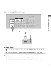
How to connect 1 Connect the digital set-top box to the owner's manual for the digital set . 2 No separated audio connection is necessary. How to use I Turn on the digital set-top box. (Refer to HDMI/DVI IN1, 2 ... IN RGB(PC) AUDIO (RGB/DV COMPONENT IN 2 1 1 VIDEO 1 HDMI-DTV OUTPUT HDMI-DTV mode Resolution Horizontal Frequency(KHz) Vertical Frequency(Hz) 720 x 480p 31.47 31.50 59.94 60.00 1280 x 720p 44.96 45.00 59.94 60.00 1920 x 1080i 33.72 33.75 59.94 60...
How to connect 1 Connect the digital set-top box to the owner's manual for the digital set . 2 No separated audio connection is necessary. How to use I Turn on the digital set-top box. (Refer to HDMI/DVI IN1, 2 ... IN RGB(PC) AUDIO (RGB/DV COMPONENT IN 2 1 1 VIDEO 1 HDMI-DTV OUTPUT HDMI-DTV mode Resolution Horizontal Frequency(KHz) Vertical Frequency(Hz) 720 x 480p 31.47 31.50 59.94 60.00 1280 x 720p 44.96 45.00 59.94 60.00 1920 x 1080i 33.72 33.75 59.94 60...
Owner's Manual (English)
Page 23
... connecting HDMI to use I Select HDMI1, HDMI2 or HDMI3 input source with using the INPUT button on the digital set-top box. (Refer to the owner's manual for the digital set . 2. How to connect 1 Connect the DVI output of the digital set-top box to the HDMI/DVI IN1, 2 or 3 jack on...
... connecting HDMI to use I Select HDMI1, HDMI2 or HDMI3 input source with using the INPUT button on the digital set-top box. (Refer to the owner's manual for the digital set . 2. How to connect 1 Connect the DVI output of the digital set-top box to the HDMI/DVI IN1, 2 or 3 jack on...
Owner's Manual (English)
Page 26
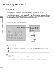
... EQUIPMENT SETUP EXTERNAL EQUIPMENT SETUP VCR SETUP I Insert a video tape into the VCR and press PLAY on the VCR. (Refer to the VCR owner's manual.) 24 ( ) When connecting with an antenna GB IN AUDIO (RGB/DVI) MPONENT IN ANTENNA/ CABLE IN REMOTE DIGITAL AUDIO OUT CONTROL IN OPTICAL...OUT S-VIDEO VIDEO L R ANT IN OUTPUT SWITCH Wall Jack 2 Antenna 1. I To avoid picture noise (interference), leave an adequate distance between the VCR and TV. If the 4:3 picture format is common to avoid having a fixed image remain on the screen for a long period of the VCR to the ANTENNA/CABLE...
... EQUIPMENT SETUP EXTERNAL EQUIPMENT SETUP VCR SETUP I Insert a video tape into the VCR and press PLAY on the VCR. (Refer to the VCR owner's manual.) 24 ( ) When connecting with an antenna GB IN AUDIO (RGB/DVI) MPONENT IN ANTENNA/ CABLE IN REMOTE DIGITAL AUDIO OUT CONTROL IN OPTICAL...OUT S-VIDEO VIDEO L R ANT IN OUTPUT SWITCH Wall Jack 2 Antenna 1. I To avoid picture noise (interference), leave an adequate distance between the VCR and TV. If the 4:3 picture format is common to avoid having a fixed image remain on the screen for a long period of the VCR to the ANTENNA/CABLE...
Owner's Manual (English)
Page 27
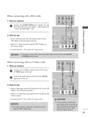
... connected to the AUDIO input jacks on the remote control. NOTE G The picture quality is improved: compared to connect 1 Connect the AUDIO/VIDEO jacks between TV and VCR. ANT IN S-VIDEO VIDEO L R ANT OUT OUTPUT SWITCH 2 Connect the audio outputs of the VCR to AV IN2, select A V 2... 1. How to normal composite (RCA cable) input. In the event that you have a mono VCR, connect the audio cable from the VCR to the VCR owner's manual.) ANTENNA/ CABLE IN 1 REMOTE CONTROL IN DIGITAL A2UDIO OUT OPTIC(AL )COAXIAL RS-232C IN (CONTROL & SERVICE) AUDIO OUT AV IN 1 I Select A ...
... connected to the AUDIO input jacks on the remote control. NOTE G The picture quality is improved: compared to connect 1 Connect the AUDIO/VIDEO jacks between TV and VCR. ANT IN S-VIDEO VIDEO L R ANT OUT OUTPUT SWITCH 2 Connect the audio outputs of the VCR to AV IN2, select A V 2... 1. How to normal composite (RCA cable) input. In the event that you have a mono VCR, connect the audio cable from the VCR to the VCR owner's manual.) ANTENNA/ CABLE IN 1 REMOTE CONTROL IN DIGITAL A2UDIO OUT OPTIC(AL )COAXIAL RS-232C IN (CONTROL & SERVICE) AUDIO OUT AV IN 1 I Select A ...


