Owners Manual
Page 2
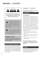
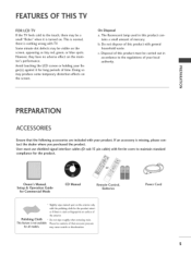
... can radiate radio frequency energy and, if not installed and used in accordance with the limits for proper grounding and, in particular, specifies that the cable ground shall be determined by the party responsible for help. Reorient or relocate the receiving antenna. - Any changes or modifications not expressly approved by turning the equipment off and on a circuit different...
... can radiate radio frequency energy and, if not installed and used in accordance with the limits for proper grounding and, in particular, specifies that the cable ground shall be determined by the party responsible for help. Reorient or relocate the receiving antenna. - Any changes or modifications not expressly approved by turning the equipment off and on a circuit different...
Owners Manual
Page 4
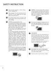
... not expose to unplug the TV. Be sure do not expose this could result in . Do not try to ground the unit by the hanging power and signal cables on the power cord to dripping or splashing and do not drop onto the screen with a three-prong grounded AC plug must remain readily operable. Keep the product away from...
... not expose to unplug the TV. Be sure do not expose this could result in . Do not try to ground the unit by the hanging power and signal cables on the power cord to dripping or splashing and do not drop onto the screen with a three-prong grounded AC plug must remain readily operable. Keep the product away from...
Owners Manual
Page 6
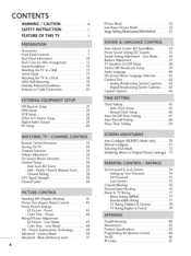
... Manual Configure 71 Selecting XGA Mode 72 Initializing (Reset to a Desk 18 VESA Wall Mounting 19 Desktop Pedestal Installation 19 Antenna or Cable Connection 20 HD Receiver Setup 21 DVD Setup 24 VCR Setup 26 Other A/V Source Setup 28 Digital Audio Output 28 PC Setup 29 Remote Control Functions 32 Turning On TV 34 Channel Selection 34 Volume Adjustment 34 On-Screen Menus Selection 35 Channel Setup 36 - Setting up Your Password 74 - Downloadable Rating 77 - TV Rating English & French 79 Troubleshooting 80 Maintenance 82 Product Specifications...
... Manual Configure 71 Selecting XGA Mode 72 Initializing (Reset to a Desk 18 VESA Wall Mounting 19 Desktop Pedestal Installation 19 Antenna or Cable Connection 20 HD Receiver Setup 21 DVD Setup 24 VCR Setup 26 Other A/V Source Setup 28 Digital Audio Output 28 PC Setup 29 Remote Control Functions 32 Turning On TV 34 Channel Selection 34 Volume Adjustment 34 On-Screen Menus Selection 35 Channel Setup 36 - Setting up Your Password 74 - Downloadable Rating 77 - TV Rating English & French 79 Troubleshooting 80 Maintenance 82 Product Specifications...
Owners Manual
Page 7
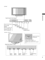
... pressure for all models. OF THiS TV FOR LCD TV If the TV feels cold to the touch, there may be carried out in this product with TV. However, they have no adverse effect on the screen. Doing so may cause scratch or discoloration. On Disposal a. Do not dispose of mercury. Owner's Manual, Setup & Operation Guide for Commercial Mode CD Manual Remote Control, Batteries * Slightly wipe...
... pressure for all models. OF THiS TV FOR LCD TV If the TV feels cold to the touch, there may be carried out in this product with TV. However, they have no adverse effect on the screen. Doing so may cause scratch or discoloration. On Disposal a. Do not dispose of mercury. Owner's Manual, Setup & Operation Guide for Commercial Mode CD Manual Remote Control, Batteries * Slightly wipe...
Owners Manual
Page 11
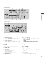
TT INPUT Button MENU Button ENTER Button VOLUME (-,+) Buttons CHANNEL (T, A) Buttons 9 POWER Button INPUT Button MENU Button ENTER Button VOLUME Buttons CHANNEL Buttons 42PG60C, 42PG65C Stand (Only42PG65C model) Remote Control Sensor POWER Button Power/Standby Indicator llluminates red in standby mode. 42PX8DC -0 _o m _o This TV's stand is sold, separately. © z Remote Control Sensor Power/Sta nd by Indicator llluminates red when the TV is switched on . llluminates green when the TV is in standby mode. Illuminates blue when the set is switched on .
TT INPUT Button MENU Button ENTER Button VOLUME (-,+) Buttons CHANNEL (T, A) Buttons 9 POWER Button INPUT Button MENU Button ENTER Button VOLUME Buttons CHANNEL Buttons 42PG60C, 42PG65C Stand (Only42PG65C model) Remote Control Sensor POWER Button Power/Standby Indicator llluminates red in standby mode. 42PX8DC -0 _o m _o This TV's stand is sold, separately. © z Remote Control Sensor Power/Sta nd by Indicator llluminates red when the TV is switched on . llluminates green when the TV is in standby mode. Illuminates blue when the set is switched on .
Owners Manual
Page 13
Note: In standby mode, these ports do not work. @ _ M.RI O RESET/UPDATE/REMOTE CONTROL OUT SERVICEONLY RGB IN (PC) Connect the output from an S-VIDEO device. COMPONENT IN Connect a component jacks. AUDIO IN (RGB, DVI) Connect the audio from various types of equipment. video/audio device to these @ RJP INTERFACE Power Cord Socket For operation with AC power. Caution: Never attempt to operate the TV on DC power. 0 ANTENNA IN Connect over-the air signals to either input. @ DIGITAL AUDIO OUT Connect digital audio from a PC or...
Note: In standby mode, these ports do not work. @ _ M.RI O RESET/UPDATE/REMOTE CONTROL OUT SERVICEONLY RGB IN (PC) Connect the output from an S-VIDEO device. COMPONENT IN Connect a component jacks. AUDIO IN (RGB, DVI) Connect the audio from various types of equipment. video/audio device to these @ RJP INTERFACE Power Cord Socket For operation with AC power. Caution: Never attempt to operate the TV on DC power. 0 ANTENNA IN Connect over-the air signals to either input. @ DIGITAL AUDIO OUT Connect digital audio from a PC or...
Owners Manual
Page 14
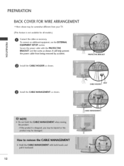
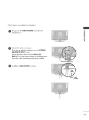
It will help prevent © the power cable from your TV. (This feature is not available for all models.) Connect the cables as shown. Z PROTECTIVE BRACKET Install the CABLE HOLDER as shown. Secure the power cable with the PROTECTIVE BRACKET and the screw as shown. Install the CABLE MANAGEMENT as necessary. PREPARATION BACK COVERFORWIREARRANGEMENT ,,,IHere shown may be somewhat different from being removed by accident. To connect an additional equipment, see the EXTERNAL EQUIPMENT SETUP section. CABLE HOLDER BOLT 12
It will help prevent © the power cable from your TV. (This feature is not available for all models.) Connect the cables as shown. Z PROTECTIVE BRACKET Install the CABLE HOLDER as shown. Secure the power cable with the PROTECTIVE BRACKET and the screw as shown. Install the CABLE MANAGEMENT as necessary. PREPARATION BACK COVERFORWIREARRANGEMENT ,,,IHere shown may be somewhat different from being removed by accident. To connect an additional equipment, see the EXTERNAL EQUIPMENT SETUP section. CABLE HOLDER BOLT 12
Owners Manual
Page 15
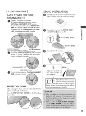
To connect an additional equipment, see the EXTERNAL EQUIPMENT SETUP section. It will help prevent the power cable from being removed by accident. Secure the power cable with the PROTECTIVE BRACKET and the screw as shown. _D m _D © z PROTECTIVE BRACKET BOLT CABLE HOLDER \ 13 Install the CABLE HOLDER as shown. (This feature is not available for all models.) To separate the CABLE HOLDER, loosen the bolt installed the set. @ Connect the cables as necessary.
To connect an additional equipment, see the EXTERNAL EQUIPMENT SETUP section. It will help prevent the power cable from being removed by accident. Secure the power cable with the PROTECTIVE BRACKET and the screw as shown. _D m _D © z PROTECTIVE BRACKET BOLT CABLE HOLDER \ 13 Install the CABLE HOLDER as shown. (This feature is not available for all models.) To separate the CABLE HOLDER, loosen the bolt installed the set. @ Connect the cables as necessary.
Owners Manual
Page 17
... power cable with COVER BASE of the TV. If your TV has the CABLE HOLDER, install it as parts of the TV) to protect the screen from being removed by accident. Assemble the TV as parts of the TV). 15 COVER into the TV until you 4 or J f _ _ Tighten the two of the STAND BODY -0 _o with the PROTECTIVE BRACKET/Screw or PLUG IN TYPE HOLDER for power code. 32/3 7/42LGSooH BACK COVERFORWIRE ARRANGEMENT STAND INSTALLATION...
... power cable with COVER BASE of the TV. If your TV has the CABLE HOLDER, install it as parts of the TV) to protect the screen from being removed by accident. Assemble the TV as parts of the TV). 15 COVER into the TV until you 4 or J f _ _ Tighten the two of the STAND BODY -0 _o with the PROTECTIVE BRACKET/Screw or PLUG IN TYPE HOLDER for power code. 32/3 7/42LGSooH BACK COVERFORWIRE ARRANGEMENT STAND INSTALLATION...
Owners Manual
Page 23
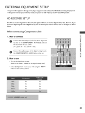
... COMPONENT IN VIDEO jacks on m the set -top box.) Select Component input source with using the INPUT button on the remote control. m c 2. Yes No Yes Yes Yes Yes Yes Yes 21 EXTERNAL EQUIPMENT SETUP 01T_o prevent the equipment damage, never plug in any power cords until you box or other digital external device, refer to the owner's manual for LCD TV(Except 32/37/42LGSOOH) models. signals without an external digital set . m Connect the audio output of the digital set z top box to use picture for the digital set...
... COMPONENT IN VIDEO jacks on m the set -top box.) Select Component input source with using the INPUT button on the remote control. m c 2. Yes No Yes Yes Yes Yes Yes Yes 21 EXTERNAL EQUIPMENT SETUP 01T_o prevent the equipment damage, never plug in any power cords until you box or other digital external device, refer to the owner's manual for LCD TV(Except 32/37/42LGSOOH) models. signals without an external digital set . m Connect the audio output of the digital set z top box to use picture for the digital set...

Owners Manual
Page 24
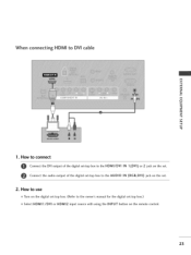
m x No separated audio connection is necessary. How to use "O m Turn on the set. z _> m _D c 2. "O 22 m _o HDMI supports both audio and video. How to connect Connect the digital set-top box to the owner's manual for the digital set -top box. z (Refer to HDMI/DVI IN 1 (DVI) or 2 jack on the digital set -top box.) m Select HDMI1/DVI or HDMI2 input source with using c the INPUT button on the remote control. EXTERNALEQUIPMENT SETUP When connecting HDM[ cable 1.
m x No separated audio connection is necessary. How to use "O m Turn on the set. z _> m _D c 2. "O 22 m _o HDMI supports both audio and video. How to connect Connect the digital set-top box to the owner's manual for the digital set -top box. z (Refer to HDMI/DVI IN 1 (DVI) or 2 jack on the digital set -top box.) m Select HDMI1/DVI or HDMI2 input source with using c the INPUT button on the remote control. EXTERNALEQUIPMENT SETUP When connecting HDM[ cable 1.
Owners Manual
Page 25
How to use 01T_urn on the digital set-top box. (Refer to the AUDIO IN (RGB,DVI) jack on the remote control. 23 When connecting HDM[ to the HDMI/DVI IN 1 (DVI) or 2 jack on the set -top box.) 01S_elect HDMI1/DVI or HDMI2 input source with using the INPUT button on the set. 2. How to connect Connect the DVI output of the digital set-top box to the owner's manual for the digital set . Connect the audio output of the digital set-top box to DVi cable m x m _o z m XZ) c @ m z m c 1.
How to use 01T_urn on the digital set-top box. (Refer to the AUDIO IN (RGB,DVI) jack on the remote control. 23 When connecting HDM[ to the HDMI/DVI IN 1 (DVI) or 2 jack on the set -top box.) 01S_elect HDMI1/DVI or HDMI2 input source with using the INPUT button on the set. 2. How to connect Connect the DVI output of the digital set-top box to the owner's manual for the digital set . Connect the audio output of the digital set-top box to DVi cable m x m _o z m XZ) c @ m z m c 1.
Owners Manual
Page 26
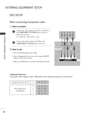
... COMPONENT IN AUDIO jacks on the set . m m Select Component input source with using the INPUT c button on the remote control. -0 m Refer to use m z m Turn on DVD player 24 Component ports on the TV Video output ports on the DVD player, insert a DVD. EXTERNALEQUIPMENT SETUP DVD SETUP When connect+ng Component 1. How to the DVD player's manual for operating instructions. m XD c 2. How to connect cable Connect the video outputs (Y, PB, PR) of the DVD to the component input ports as shown below. Match the jack colors m x (Y = green, PB = blue, and PR = red...
... COMPONENT IN AUDIO jacks on the set . m m Select Component input source with using the INPUT c button on the remote control. -0 m Refer to use m z m Turn on DVD player 24 Component ports on the TV Video output ports on the DVD player, insert a DVD. EXTERNALEQUIPMENT SETUP DVD SETUP When connect+ng Component 1. How to the DVD player's manual for operating instructions. m XD c 2. How to connect cable Connect the video outputs (Y, PB, PR) of the DVD to the component input ports as shown below. Match the jack colors m x (Y = green, PB = blue, and PR = red...
Owners Manual
Page 27
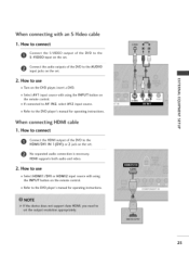
... DVD player, insert a DVD. How to connect -0 Connect the HDMI output of the DVD to use 01_Select HDMI1/DVI or HDMI2 input source with using the INPUT button on the set . z 01_Select AV1 input source with using the INPUT button on the set . m XD c 01_If connected to AV IN2, select AV2 input source. 01_Refer to the HDMI/DVI IN 1 (DVI) or 2 jack on the remote control. HDMI supports both audio and video. 2. When connecting with an S-Video cable 1. Connect the audio outputs of the DVD to the DVD player's manual for operating instructions...
... DVD player, insert a DVD. How to connect -0 Connect the HDMI output of the DVD to use 01_Select HDMI1/DVI or HDMI2 input source with using the INPUT button on the set . z 01_Select AV1 input source with using the INPUT button on the set . m XD c 01_If connected to AV IN2, select AV2 input source. 01_Refer to the HDMI/DVI IN 1 (DVI) or 2 jack on the remote control. HDMI supports both audio and video. 2. When connecting with an S-Video cable 1. Connect the audio outputs of the DVD to the DVD player's manual for operating instructions...
Owners Manual
Page 29
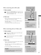
... connected to connect Connect the AUDIO/VIDEO jacks between TV and VCR. m z m c -0 When connecting with a RCA cable 1. of the VCR to the Connect the audio outputs of the VCR to the VCR owner's manual.) 01_Select AV1 input source with using the INPUT button on the remote control. 01_If connected to connect Connect the S-VIDEO output S-VIDEO input on the set . How to use m x 01I_nsert a video tape into the VCR and press PLAY on the VCR. (Refer to the AUDIO input jacks on the set...
... connected to connect Connect the AUDIO/VIDEO jacks between TV and VCR. m z m c -0 When connecting with a RCA cable 1. of the VCR to the Connect the audio outputs of the VCR to the VCR owner's manual.) 01_Select AV1 input source with using the INPUT button on the remote control. 01_If connected to connect Connect the S-VIDEO output S-VIDEO input on the set . How to use m x 01I_nsert a video tape into the VCR and press PLAY on the VCR. (Refer to the AUDIO input jacks on the set...
Owners Manual
Page 30
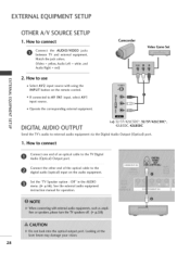
... the remote control. How to connect Connect one end of the optical cable to use x m 01_Select AV2 input source with using the z INPUT button on the audio equipment. Off" in the AUDIO menu. (_ p.58). EXTERNALEQUIPMENT SETUP OTHER A/V SOURCESETUP 1. m z m c DIGITAL AUDIO OUTPUT i.e) 32137142LC5DC*, 32/37/42LCS0C*, 42LB5DC, 42LBS0C Send the TV's audio to AV IN 1 input, select AV 1 _D c input source. 01_Operate the corresponding external equipment. Match the jack colors. (Video = yellow, Audio Left = white, and Audio Right = red) Camcorder Video Game Set m 2. Connect...
... the remote control. How to connect Connect one end of the optical cable to use x m 01_Select AV2 input source with using the z INPUT button on the audio equipment. Off" in the AUDIO menu. (_ p.58). EXTERNALEQUIPMENT SETUP OTHER A/V SOURCESETUP 1. m z m c DIGITAL AUDIO OUTPUT i.e) 32137142LC5DC*, 32/37/42LCS0C*, 42LB5DC, 42LBS0C Send the TV's audio to AV IN 1 input, select AV 1 _D c input source. 01_Operate the corresponding external equipment. Match the jack colors. (Video = yellow, Audio Left = white, and Audio Right = red) Camcorder Video Game Set m 2. Connect...
Owners Manual
Page 31
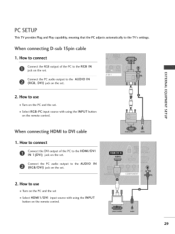
... the set SelectHDMII/DVI input source with using the INPUT button on the set . PC SETUP This TV provides Plug and Play capability, meaning that the PC adjusts automatically to the RGB IN jack on the remote control. 29 How to connect Connect the RGB output of the PC to the AUDIO IN m _o (RGB, DVl) jack on the set . x Connect the PC audio output to the HDMI/DVI IN I . When connecting D-sub 1Spin cable...
... the set SelectHDMII/DVI input source with using the INPUT button on the set . PC SETUP This TV provides Plug and Play capability, meaning that the PC adjusts automatically to the RGB IN jack on the remote control. 29 How to connect Connect the RGB output of the PC to the AUDIO IN m _o (RGB, DVl) jack on the set . x Connect the PC audio output to the HDMI/DVI IN I . When connecting D-sub 1Spin cable...
Owners Manual
Page 34
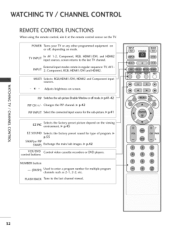
... images. _ p.42 VCR/DVD Control video cassette recorders or DVD players. INPUT External input modes rotate in regular sequence: TV, AV1 2, Component, RGB, HDMI1/DVI and HDMI2. FLASH BACK Tune to the last channel viewed. 32 POWER Turns your TV or any other programmed equipment on the viewing N environment. @ p.45 © Z EZ SOUND Selects the factory preset sound for multiple program channels such as 2-1,2-2, etc. HiNG TV / CHANNEL CONTROL REMOTE CONTROL FUNCTIONS When using the remote control, aim it at the remote control sensor on mode. MULTI...
... images. _ p.42 VCR/DVD Control video cassette recorders or DVD players. INPUT External input modes rotate in regular sequence: TV, AV1 2, Component, RGB, HDMI1/DVI and HDMI2. FLASH BACK Tune to the last channel viewed. 32 POWER Turns your TV or any other programmed equipment on the viewing N environment. @ p.45 © Z EZ SOUND Selects the factory preset sound for multiple program channels such as 2-1,2-2, etc. HiNG TV / CHANNEL CONTROL REMOTE CONTROL FUNCTIONS When using the remote control, aim it at the remote control sensor on mode. MULTI...
Owners Manual
Page 76
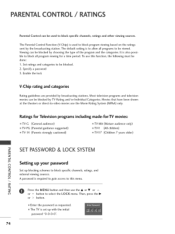
... password "0-0-0-0". 74 To use this menu. _D z Press the MENU button and then use the Movie Rating System (MPAA) only. The Parental Control Function (V-Chip) is to block specific channels, ratings and other viewing sources. It is required to gain access to be done: 1. Then, press the • or > button. 01E_nter the password as requested. 01T_he TV is set up blocking schemes to block specific channels, ratings, and _D external viewing sources...
... password "0-0-0-0". 74 To use this menu. _D z Press the MENU button and then use the Movie Rating System (MPAA) only. The Parental Control Function (V-Chip) is to block specific channels, ratings and other viewing sources. It is required to gain access to be done: 1. Then, press the • or > button. 01E_nter the password as requested. 01T_he TV is set up blocking schemes to block specific channels, ratings, and _D external viewing sources...
Owners Manual
Page 78
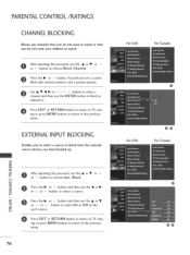
... or press MENU button to return to TV view- You will now see a screen filled with channel numbers and a preview picture. Press EXIT or RETURN button to return to TV viewing or press MENU button to return to watch or that you do not want your children to the previous menu. After inputting the password, use the • or • or ^ or v button to choose Block Channel. EXTERNAL INPUT BLOCKING Enables...
... or press MENU button to return to TV view- You will now see a screen filled with channel numbers and a preview picture. Press EXIT or RETURN button to return to TV viewing or press MENU button to return to watch or that you do not want your children to the previous menu. After inputting the password, use the • or • or ^ or v button to choose Block Channel. EXTERNAL INPUT BLOCKING Enables...


