Specification
Page 1
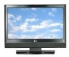
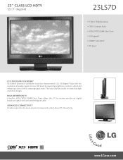
advanced connectivity Includes inputs for the most advanced components which allows PC interactivity. LG's XD Engine® takes the low resolution of analog signals to picture improvement. 23" CLASS LCD HDTV (22.9" diagonal) 23LS7D • 1366 x 768p Resolution • 700:1 Contrast Ratio • ATSC/NTSC/QAM Clear...and enhancing color as well as reducing signal noise. High Definition TV A built-in cinema-like high resolution images. This total solution results in ATSC/NTSC/QAM Clear Tuner allows this TV to receive over-the-air digital broadcast signals and unscrambled digital ...
advanced connectivity Includes inputs for the most advanced components which allows PC interactivity. LG's XD Engine® takes the low resolution of analog signals to picture improvement. 23" CLASS LCD HDTV (22.9" diagonal) 23LS7D • 1366 x 768p Resolution • 700:1 Contrast Ratio • ATSC/NTSC/QAM Clear...and enhancing color as well as reducing signal noise. High Definition TV A built-in cinema-like high resolution images. This total solution results in ATSC/NTSC/QAM Clear Tuner allows this TV to receive over-the-air digital broadcast signals and unscrambled digital ...
Specification
Page 2
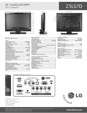
...10 Bit Audio Mono/Stereo/Dual (MTS/SAP) • Audio Output Power (Watts - 23" CLASS LCD HDTV (22.9" diagonal) 22.9" 3.3" 23LS7D 3.9" 3.9" 18.1" 16.3" 7.8" 14.4" TV ATSC/NTSC/QAM Clear Tuner • Video Native Display Resolution 1366 x 768p Contrast Ratio 700... (D-Sub 15pin) - Dimensions w/Packaging (W x H x D) 25.8" x 19.3" x 21.6" Weight In Package 21.6 lbs. LG Design and Life's Good are the property of LG Electronics, Inc. PC 1 PC Audio Input 1 RS-232c In (Control/Service) 1 Headphone In 1 USB (Service only) •...
...10 Bit Audio Mono/Stereo/Dual (MTS/SAP) • Audio Output Power (Watts - 23" CLASS LCD HDTV (22.9" diagonal) 22.9" 3.3" 23LS7D 3.9" 3.9" 18.1" 16.3" 7.8" 14.4" TV ATSC/NTSC/QAM Clear Tuner • Video Native Display Resolution 1366 x 768p Contrast Ratio 700... (D-Sub 15pin) - Dimensions w/Packaging (W x H x D) 25.8" x 19.3" x 21.6" Weight In Package 21.6 lbs. LG Design and Life's Good are the property of LG Electronics, Inc. PC 1 PC Audio Input 1 RS-232c In (Control/Service) 1 Headphone In 1 USB (Service only) •...

Owner's Manual (English)
Page 1
ENERGY STAR is a set . LCD TV OWNER'S MANUAL 20LS7D 20LS7DC 23LS7D 23LS7DC Please read this manual carefully before operating your dealer when you require service. A.,Inc. has determined that this information to your set of the ... attached on the back cover and quote this product meets the ENERGY STAR guidelines for future reference. Environmental Protection Agency(EPA). www.lgusa.com / www.lg.ca / www.lgcommercial.com As an ENERGY STAR Partner LGE U. S. Retain it for energy efficiency. Record model number and serial number of power-saving guidelines...
ENERGY STAR is a set . LCD TV OWNER'S MANUAL 20LS7D 20LS7DC 23LS7D 23LS7DC Please read this manual carefully before operating your dealer when you require service. A.,Inc. has determined that this information to your set of the ... attached on the back cover and quote this product meets the ENERGY STAR guidelines for future reference. Environmental Protection Agency(EPA). www.lgusa.com / www.lg.ca / www.lgcommercial.com As an ENERGY STAR Partner LGE U. S. Retain it for energy efficiency. Record model number and serial number of power-saving guidelines...
Owner's Manual (English)
Page 3
.... However, there is intended to alert the user to correct the interference by turning the equipment off and on a circuit different from LG Electronics. Connect the equipment to an outlet on , the user is connected. - If this product in the literature accompanying the appliance. NOTE... TO CABLE/TV INSTALLER This reminder is provided to call the CATV system installer's attention to Article 820-40 of electric shock to radio or television reception...
.... However, there is intended to alert the user to correct the interference by turning the equipment off and on a circuit different from LG Electronics. Connect the equipment to an outlet on , the user is connected. - If this product in the literature accompanying the appliance. NOTE... TO CABLE/TV INSTALLER This reminder is provided to call the CATV system installer's attention to Article 820-40 of electric shock to radio or television reception...

Owner's Manual (English)
Page 6
...PICTURE CONTROL Picture Size (Aspect Ratio) Control 36 Preset Picture Settings - CONTENTS WARNING / CAUTION 1 SAFETY INSTRUCTIONS 2 INTRODUCTION Feature of this TV 6 PREPARATION Accessories 7 Front Panel Information 8 Back Panel Information 9 Stand Installation 10 Detaching Stand 11 Back Cover for Wire Arrangement 12 ...Positioning your display 13 VESA Wall Mounting 14 Desktop Pedestal Installation 14 Kensington Security System 15 Attaching the TV to a Desk 15 Antenna or Cable Connection 16 EXTERNAL EQUIPMENT SETUP HD Receiver Setup 17 DVD Setup 20 VCR...
...PICTURE CONTROL Picture Size (Aspect Ratio) Control 36 Preset Picture Settings - CONTENTS WARNING / CAUTION 1 SAFETY INSTRUCTIONS 2 INTRODUCTION Feature of this TV 6 PREPARATION Accessories 7 Front Panel Information 8 Back Panel Information 9 Stand Installation 10 Detaching Stand 11 Back Cover for Wire Arrangement 12 ...Positioning your display 13 VESA Wall Mounting 14 Desktop Pedestal Installation 14 Kensington Security System 15 Attaching the TV to a Desk 15 Antenna or Cable Connection 16 EXTERNAL EQUIPMENT SETUP HD Receiver Setup 17 DVD Setup 20 VCR...
Owner's Manual (English)
Page 8
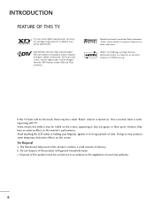
...audio. However, they have no adverse effect on the screen, appearing as tiny red, green, or blue spots. Avoid touching the LCD screen or holding your local authority. 6 On Disposal a. Do not dispose of Dolby Laboratories. High-definition television. Manufactured under license ... temporary distortion effects on . Disposal of your finger(s) against it is nothing wrong with general household waste. INTRODUCTION FEATURE OF THIS TV LG's own special digital image generator, consisting of HDMI Licensing." "Dolby "and the double-D symbol are trademarks or registered trademarks of ...
...audio. However, they have no adverse effect on the screen, appearing as tiny red, green, or blue spots. Avoid touching the LCD screen or holding your local authority. 6 On Disposal a. Do not dispose of Dolby Laboratories. High-definition television. Manufactured under license ... temporary distortion effects on . Disposal of your finger(s) against it is nothing wrong with general household waste. INTRODUCTION FEATURE OF THIS TV LG's own special digital image generator, consisting of HDMI Licensing." "Dolby "and the double-D symbol are trademarks or registered trademarks of ...
Owner's Manual (English)
Page 9
...is missing, please contact the dealer where you purchased the product. D-sub 15 pin Cable 7 LCD TV Owner's Manual 1 4 2 SOUND NPUT TIMER 7 5 3 - 8 6 0 9 VOL ADJUST FAV MUTE CC CH BACK EXIT TV SAP POWER PICTURE 1 SOUND INPUT 4 2 TIMER 7 5 3 - 8 6 0 9 MENU... VOL ADJUST MUTE CC CH BACK EXIT FAV 1.5V 1.5V ENTER http://www.lgusa.com www.lg.ca Copyright© 2007 LGE, All Rights Reserved. Owner's Manual ...
...is missing, please contact the dealer where you purchased the product. D-sub 15 pin Cable 7 LCD TV Owner's Manual 1 4 2 SOUND NPUT TIMER 7 5 3 - 8 6 0 9 VOL ADJUST FAV MUTE CC CH BACK EXIT TV SAP POWER PICTURE 1 SOUND INPUT 4 2 TIMER 7 5 3 - 8 6 0 9 MENU... VOL ADJUST MUTE CC CH BACK EXIT FAV 1.5V 1.5V ENTER http://www.lgusa.com www.lg.ca Copyright© 2007 LGE, All Rights Reserved. Owner's Manual ...

Owner's Manual (English)
Page 10
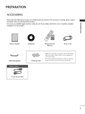
PREPARATION PREPARATION FRONT PANEL INFORMATION I INPUT MENU ENTER VOL CH Remote Control Sensor Power/Standby Indicator Illuminates red in standby mode. NOTE G If your TV. Illuminates green when the set is included with a cloth (If a polishing cloth is switched on. ! And then wipe the product with your product, use it). 8 POWER INPUT MENU ENTER VOLUME CHANNEL Button Button Button Button (F,G)Buttons (E,D)Buttons /I Here shown may be somewhat different from your product has a protection tape attached, remove the tape.
PREPARATION PREPARATION FRONT PANEL INFORMATION I INPUT MENU ENTER VOL CH Remote Control Sensor Power/Standby Indicator Illuminates red in standby mode. NOTE G If your TV. Illuminates green when the set is included with a cloth (If a polishing cloth is switched on. ! And then wipe the product with your product, use it). 8 POWER INPUT MENU ENTER VOLUME CHANNEL Button Button Button Button (F,G)Buttons (E,D)Buttons /I Here shown may be somewhat different from your product has a protection tape attached, remove the tape.

Owner's Manual (English)
Page 11
Connect cable signals to this jack. Caution: Never attempt to DVI cable. 3 AV IN (Audio/Video) Connect audio/video output from your TV. PREPARATION 8 2 HDMI/DVI IN 3 ANTENNA/ CABLE IN 4 1 SERVICE ONLY AV IN S-VIDEO AUDIO VIDEO AUDIO RGB (PC) IN (RGB/DVI) IN 5 L(MONO) R H/P RS-232C IN (... video/audio device to these jacks. 7 HEADPHONE INPUT Plug the headphone into the headphone socket. 8 Power Cord Socket For operation with a HDMI to operate the TV on DC power. 9
Connect cable signals to this jack. Caution: Never attempt to DVI cable. 3 AV IN (Audio/Video) Connect audio/video output from your TV. PREPARATION 8 2 HDMI/DVI IN 3 ANTENNA/ CABLE IN 4 1 SERVICE ONLY AV IN S-VIDEO AUDIO VIDEO AUDIO RGB (PC) IN (RGB/DVI) IN 5 L(MONO) R H/P RS-232C IN (... video/audio device to these jacks. 7 HEADPHONE INPUT Plug the headphone into the headphone socket. 8 Power Cord Socket For operation with a HDMI to operate the TV on DC power. 9

Owner's Manual (English)
Page 12
HINGE BODY 3 Insert the STAND BODY into the product until clicking sound. STAND BODY 4 Assemble the parts of the STAND BODY with COVER BASE of the product. COVER BASE 10 PREPARATION PREPARATION STAND INSTALLATION I Here shown may be somewhat different from your TV. 1 Carefully place the product screen side down on a cushioned surface that will protect product and screen from damage. 2 Hold the HINGE BODY and bend it upward.
HINGE BODY 3 Insert the STAND BODY into the product until clicking sound. STAND BODY 4 Assemble the parts of the STAND BODY with COVER BASE of the product. COVER BASE 10 PREPARATION PREPARATION STAND INSTALLATION I Here shown may be somewhat different from your TV. 1 Carefully place the product screen side down on a cushioned surface that will protect product and screen from damage. 2 Hold the HINGE BODY and bend it upward.

Owner's Manual (English)
Page 13
PREPARATION DETACHING STAND I Here shown may be somewhat different from your TV. 1 Carefully place the product screen side down on a cushioned surface that will protect product and screen from damage. 2 Pull cover base backward while pressing button on stand body. 3 Shake the base while pulling, it will separate from set while press- HINGE BODY 5 Pull stand body to separate from stand body. 4 Hold the HINGE BODY and bend it upward. ing the 2 latches. 11
PREPARATION DETACHING STAND I Here shown may be somewhat different from your TV. 1 Carefully place the product screen side down on a cushioned surface that will protect product and screen from damage. 2 Pull cover base backward while pressing button on stand body. 3 Shake the base while pulling, it will separate from set while press- HINGE BODY 5 Pull stand body to separate from stand body. 4 Hold the HINGE BODY and bend it upward. ing the 2 latches. 11
Owner's Manual (English)
Page 14
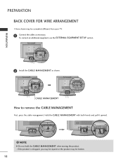
PREPARATION PREPARATION BACK COVER FOR WIRE ARRANGEMENT I Here shown may be somewhat different from your TV. 1 Connect the cables as shown. NOTE G Do not hold the CABLE MANAGEMENT when moving the product. - To connect an additional equipment, see the EXTERNAL EQUIPMENT SETUP section. 2 Install the CABLE MANAGEMENT as necessary. Hold the CABLE MANAGEMENT with both hands and pull it upward. ! If the product is dropped, you may be injured or the product may be broken. 12 CABLE MANAGEMENT How to remove the CABLE MANAGEMENT First, press the cable management.
PREPARATION PREPARATION BACK COVER FOR WIRE ARRANGEMENT I Here shown may be somewhat different from your TV. 1 Connect the cables as shown. NOTE G Do not hold the CABLE MANAGEMENT when moving the product. - To connect an additional equipment, see the EXTERNAL EQUIPMENT SETUP section. 2 Install the CABLE MANAGEMENT as necessary. Hold the CABLE MANAGEMENT with both hands and pull it upward. ! If the product is dropped, you may be injured or the product may be broken. 12 CABLE MANAGEMENT How to remove the CABLE MANAGEMENT First, press the cable management.

Owner's Manual (English)
Page 15
PREPARATION POSITIONING YOUR DISPLAY I Adjust the position of the panel in various ways for maximum comfort. • Tilt range 12~10 03 13 I Here shown may be somewhat different from your TV.
PREPARATION POSITIONING YOUR DISPLAY I Adjust the position of the panel in various ways for maximum comfort. • Tilt range 12~10 03 13 I Here shown may be somewhat different from your TV.

Owner's Manual (English)
Page 17
... guide provided with a Kensington Security System connector on the back panel. NOTE - ATTACHING THE TV TO A DESK (Only 23 inches) The TV must be pulled in a forward/backward direction, potentially causing injury or damaging the product. 2-...Screws (M3x25) (not provided as shown below. - PREPARATION KENSINGTON SECURITY SYSTEM - The TV is an optional accessory. Kensington sells security systems for expensive electronic equipment such as notebook PCs and LCD...
... guide provided with a Kensington Security System connector on the back panel. NOTE - ATTACHING THE TV TO A DESK (Only 23 inches) The TV must be pulled in a forward/backward direction, potentially causing injury or damaging the product. 2-...Screws (M3x25) (not provided as shown below. - PREPARATION KENSINGTON SECURITY SYSTEM - The TV is an optional accessory. Kensington sells security systems for expensive electronic equipment such as notebook PCs and LCD...

Owner's Manual (English)
Page 18
...wire when connecting the antenna. 2. Antenna (Analog or Digital) Wall Antenna Socket or Outdoor Antenna without a Cable Box Connections. Cable Cable TV Wall Jack RF Coaxial Wire (75 ohm) ANTENNA/ CABLE IN Antenna UHF Signal Amplifier VHF ANTENNA/ CABLE IN I If the antenna is...OR CABLE CONNECTION 1. I To improve the picture quality in a poor signal area, please purchase a signal amplifier and install properly. NOTE G The TV will let you know when the analog, cable, and digital channel scans are complete. 16 For optimum picture quality, adjust antenna direction if needed. ...
...wire when connecting the antenna. 2. Antenna (Analog or Digital) Wall Antenna Socket or Outdoor Antenna without a Cable Box Connections. Cable Cable TV Wall Jack RF Coaxial Wire (75 ohm) ANTENNA/ CABLE IN Antenna UHF Signal Amplifier VHF ANTENNA/ CABLE IN I If the antenna is...OR CABLE CONNECTION 1. I To improve the picture quality in a poor signal area, please purchase a signal amplifier and install properly. NOTE G The TV will let you know when the analog, cable, and digital channel scans are complete. 16 For optimum picture quality, adjust antenna direction if needed. ...

Owner's Manual (English)
Page 19
... use I To prevent the equipment damage, never plug in any power cords until you do receive digital signals from a digital set . 2. HD RECEIVER SETUP This TV can receive Digital Over-the-air/Cable signals without an external digital set . EXTERNAL EQUIPMENT SETUP I Turn on the remote control. How to the owner...
... use I To prevent the equipment damage, never plug in any power cords until you do receive digital signals from a digital set . 2. HD RECEIVER SETUP This TV can receive Digital Over-the-air/Cable signals without an external digital set . EXTERNAL EQUIPMENT SETUP I Turn on the remote control. How to the owner...

Owner's Manual (English)
Page 20
... the digital set-top box.) I Select H D M I input source by using the I N P U T button on the set. 2 No separated audio connection is necessary. NOTE G When connected, the TV will be automatically set to set -top box. (Refer to HDMI/DVI IN jack on the remote control. ! If the device supports this Auto HDMI...
... the digital set-top box.) I Select H D M I input source by using the I N P U T button on the set. 2 No separated audio connection is necessary. NOTE G When connected, the TV will be automatically set to set -top box. (Refer to HDMI/DVI IN jack on the remote control. ! If the device supports this Auto HDMI...

Owner's Manual (English)
Page 22
... source by using the INPUT button on the DVD player, insert a DVD. I Refer to the component input ports as shown below. Component ports on the TV Y PB PR Video output ports on the set . 1 ANTENNA/ CABLE IN 2 2. Y PB PR L R 2 Connect the audio outputs of the DVD to the COMPONENT IN AUDIO...
... source by using the INPUT button on the DVD player, insert a DVD. I Refer to the component input ports as shown below. Component ports on the TV Y PB PR Video output ports on the set . 1 ANTENNA/ CABLE IN 2 2. Y PB PR L R 2 Connect the audio outputs of the DVD to the COMPONENT IN AUDIO...

Owner's Manual (English)
Page 23
... the DVD to the DVD player's manual for operating instructions. ! I Turn on the remote control. HDMI supports both audio and video. 2. NOTE G When connected, the TV will be automatically set . 2 No separated audio connection is necessary. VI IN ANTENNA/ CABLE IN VIDEO AV IN AUDIO S-VIDEO AU RGB (PC) IN (RG...
... the DVD to the DVD player's manual for operating instructions. ! I Turn on the remote control. HDMI supports both audio and video. 2. NOTE G When connected, the TV will be automatically set . 2 No separated audio connection is necessary. VI IN ANTENNA/ CABLE IN VIDEO AV IN AUDIO S-VIDEO AU RGB (PC) IN (RG...

Owner's Manual (English)
Page 24
I To avoid picture noise (interference), leave an adequate distance between the VCR and TV. How to use I If the 4:3 picture format is common to all manufactures and in socket of the screen may remain visible on the VCR. (Refer ...to the VCR owner's manual.) 22 I Set VCR output switch to 3 or 4 and then tune TV to the RF antenna in consequence the manufactures warranty does not cover the product bearing this phenomenon. How to connect 1 Connect the RF antenna out...
I To avoid picture noise (interference), leave an adequate distance between the VCR and TV. How to use I If the 4:3 picture format is common to all manufactures and in socket of the screen may remain visible on the VCR. (Refer ...to the VCR owner's manual.) 22 I Set VCR output switch to 3 or 4 and then tune TV to the RF antenna in consequence the manufactures warranty does not cover the product bearing this phenomenon. How to connect 1 Connect the RF antenna out...


