
User Manual
Page 1
XXV-03A SUBWOOFER POWER AMPLIFIER 7 page 2-9 INSTRUCTION MANUAL AMPLIFICATEUR DE PUISSANCE DU SUBWOOFER 7 page 10-17 MODE D'EMPLOI AMPLIFICADOR DE POTENCIA DEL ALTAVOZ DE SONIDO ENVOLVENTE 7 página 18-25 MANUAL DE INSTRUCCIONES Take the time to the model and serial numbers whenever you obtain the best performance from your Kenwood product at www.kenwoodusa.com © B64-3087-00/00 (KV/EV) Model XXV-03A Serial number US Residence...
XXV-03A SUBWOOFER POWER AMPLIFIER 7 page 2-9 INSTRUCTION MANUAL AMPLIFICATEUR DE PUISSANCE DU SUBWOOFER 7 page 10-17 MODE D'EMPLOI AMPLIFICADOR DE POTENCIA DEL ALTAVOZ DE SONIDO ENVOLVENTE 7 página 18-25 MANUAL DE INSTRUCCIONES Take the time to the model and serial numbers whenever you obtain the best performance from your Kenwood product at www.kenwoodusa.com © B64-3087-00/00 (KV/EV) Model XXV-03A Serial number US Residence...
User Manual
Page 2
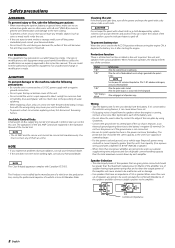
... replacing a fuse, only use a new one power amplifier are explained in the instruction manual. Changes or modifications to operate this unit directly from various problems. When Protection operates, the display informs you of the Center Unit. The user could lose the authority to this unit. Also avoid places with a negative ground connection. • Do not open the top or bottom covers of the unit becomes hot and may cause your Kenwood...
... replacing a fuse, only use a new one power amplifier are explained in the instruction manual. Changes or modifications to operate this unit directly from various problems. When Protection operates, the display informs you of the Center Unit. The user could lose the authority to this unit. Also avoid places with a negative ground connection. • Do not open the top or bottom covers of the unit becomes hot and may cause your Kenwood...
User Manual
Page 3
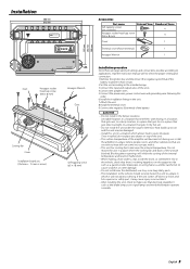
... obstruct driving. English 3 terminal of the battery to prevent short circuits. 2.Set the unit according to a shock and hits a person or safety part, it will inhibit the cooling of the units. 4.Connect the speaker wires. 5.Connect the power wire, power control wire and grounding wire following this unit in malfunction. • When making a hole under the carpet. If the unit comes off due to the intended usage. 3.Connect the input and output wires...
... obstruct driving. English 3 terminal of the battery to prevent short circuits. 2.Set the unit according to a shock and hits a person or safety part, it will inhibit the cooling of the units. 4.Connect the speaker wires. 5.Connect the power wire, power control wire and grounding wire following this unit in malfunction. • When making a hole under the carpet. If the unit comes off due to the intended usage. 3.Connect the input and output wires...
User Manual
Page 4
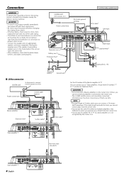
... work properly. * Commercially available parts CENTER UNIT (CD receiver, etc.) Power control wire RCA cable ground terminal GND RCA cable* Left input 789 25 25 25 Terminal cover Battery wire* Protective Fuse* 23 456 Right input Lead terminal* Subwoofer (L + R) Battery Ground wire* ■ LX-Bus connection CENTER UNIT To Kenwood disc changer/ External optional accessory Power control wire Control cable (option) 25 25 25 Master amplifier Extension wire* 456 456 "0" ID NUMBER S-video cable* 23 23 78 789 RCA cable* Set the ID number of the Master amplifier...
... work properly. * Commercially available parts CENTER UNIT (CD receiver, etc.) Power control wire RCA cable ground terminal GND RCA cable* Left input 789 25 25 25 Terminal cover Battery wire* Protective Fuse* 23 456 Right input Lead terminal* Subwoofer (L + R) Battery Ground wire* ■ LX-Bus connection CENTER UNIT To Kenwood disc changer/ External optional accessory Power control wire Control cable (option) 25 25 25 Master amplifier Extension wire* 456 456 "0" ID NUMBER S-video cable* 23 23 78 789 RCA cable* Set the ID number of the Master amplifier...

User Manual
Page 5
... terminals. 2CAUTION The rated input of the speakers should be used for amplifier control from the line input terminal is output. 1 # Power indicator Lights when the POWER switch is set to "ON", the inaudible, ultralow frequencies below the frequency set the Master amplifier, connect it as Slave amplifiers. The indicator flashes several seconds when the POWER switch is turned On or when the Protection function is set to the pre-output level of 1 ohm, connect speakers with 1-ohm or...
... terminals. 2CAUTION The rated input of the speakers should be used for amplifier control from the line input terminal is output. 1 # Power indicator Lights when the POWER switch is set to "ON", the inaudible, ultralow frequencies below the frequency set the Master amplifier, connect it as Slave amplifiers. The indicator flashes several seconds when the POWER switch is turned On or when the Protection function is set to the pre-output level of 1 ohm, connect speakers with 1-ohm or...
User Manual
Page 6
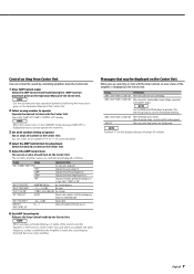
... to Bass Center Frequency Bass level Bass Q Factor When the bass extend is displayed and you can register the values you have set to The ID Number you hold down the [3] button 3 or more seconds during ID number display ("AMP"), message "MEMO" is set values are switched in the Demonstration mode. For the operation method refer to the initial (default) values. 1 Enter Menu mode Press the [MENU] button. 2 Select Default mode Press the [MENU] button...
... to Bass Center Frequency Bass level Bass Q Factor When the bass extend is displayed and you can register the values you have set to The ID Number you hold down the [3] button 3 or more seconds during ID number display ("AMP"), message "MEMO" is set values are switched in the Demonstration mode. For the operation method refer to the initial (default) values. 1 Enter Menu mode Press the [MENU] button. 2 Select Default mode Press the [MENU] button...
User Manual
Page 7
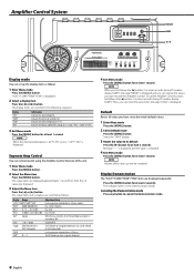
... Operation Manual of the amp you use . 6 Exit AMP Control mode Releases the Amp Control mode by the Center Unit. "VOL"/"VOL OFFSET" "AMP NO"/ "AMP CONTROL NO" -20 - 0 (dB) 0 - 7 Volume offset Select an ID number of the Center Unit. Indicates the source voltage (V). English 7 NOTE Turn the POWER switch Off and release the protection. Control an Amp from Center Unit You can control the sound by controlling amplifiers from the Center Unit. 1 Enter AMP Control mode Select the AMP Control mode by following the instructions given on the display...
... Operation Manual of the amp you use . 6 Exit AMP Control mode Releases the Amp Control mode by the Center Unit. "VOL"/"VOL OFFSET" "AMP NO"/ "AMP CONTROL NO" -20 - 0 (dB) 0 - 7 Volume offset Select an ID number of the Center Unit. Indicates the source voltage (V). English 7 NOTE Turn the POWER switch Off and release the protection. Control an Amp from Center Unit You can control the sound by controlling amplifiers from the Center Unit. 1 Enter AMP Control mode Select the AMP Control mode by following the instructions given on the display...
User Manual
Page 8
...; Adjustment using a spectrum analyzer: Output white noise (sound in the car body. • The switches may be operated from the Center • The ID number of the amplifier has been changed it with which all frequencies are disconnected. • Protection circuit may be the result of the short, replace the fuse. • Adjust the control correctly referring to minimize influence on the spectrum analyzer, and set the B.R.F. Troubleshooting Guide...
...; Adjustment using a spectrum analyzer: Output white noise (sound in the car body. • The switches may be operated from the Center • The ID number of the amplifier has been changed it with which all frequencies are disconnected. • Protection circuit may be the result of the short, replace the fuse. • Adjust the control correctly referring to minimize influence on the spectrum analyzer, and set the B.R.F. Troubleshooting Guide...
User Manual
Page 9
Specifications Specifications subject to Noise Ratio...100 dB Sensitivity (rated output) (MAX.) ...0.2 V Sensitivity (rated output) (MIN.) ...5.0 V Input Impedance ...10 kΩ Amplifier Control Section (EQ) Bass frequency ...60 / 80 / 100 / 200 Hz Bass level ...-15 - +15 dB Bass Q factor...1.00 / 1.25 / 1.50 / 2.00 General Operating Voltage ...14.4 V (11 - 16 V allowable) Current Consumption ...55 A Dimensions (W × H × D) ...386 × 61 × 259.5 mm ...15-3/16 ×...
Specifications Specifications subject to Noise Ratio...100 dB Sensitivity (rated output) (MAX.) ...0.2 V Sensitivity (rated output) (MIN.) ...5.0 V Input Impedance ...10 kΩ Amplifier Control Section (EQ) Bass frequency ...60 / 80 / 100 / 200 Hz Bass level ...-15 - +15 dB Bass Q factor...1.00 / 1.25 / 1.50 / 2.00 General Operating Voltage ...14.4 V (11 - 16 V allowable) Current Consumption ...55 A Dimensions (W × H × D) ...386 × 61 × 259.5 mm ...15-3/16 ×...


