Owner's Manual (pdf)
Page 2
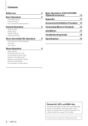
... Manual Clock Adjustment Auxiliary Input Display Setting Receive mode Setting Demonstration mode Setting 3 Basic Operations of Dolby Laboratories. The "AAC" logo is a trademark of KCA-RC60MR (Optional accessory) 12 4 Appendix 13 Accessories/Installation Procedure 15 6 Connecting Wires to Terminals 16 Installation 17 Troubleshooting Guide 18 8 Specifications 19 9 2 | KMR-330 Playing AAC, MP3, and WMA data...
... Manual Clock Adjustment Auxiliary Input Display Setting Receive mode Setting Demonstration mode Setting 3 Basic Operations of Dolby Laboratories. The "AAC" logo is a trademark of KCA-RC60MR (Optional accessory) 12 4 Appendix 13 Accessories/Installation Procedure 15 6 Connecting Wires to Terminals 16 Installation 17 Troubleshooting Guide 18 8 Specifications 19 9 2 | KMR-330 Playing AAC, MP3, and WMA data...
Owner's Manual (pdf)
Page 3
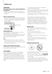
... settings when the Reset button is stained, wipe it . • Do not use disc type accessories. • Clean from the center of the disc and move outward. • When removing CDs from what appears on the display in the illustrations may be inapplicable. Lens Fogging When you purchase ...optional accessories, check with your Kenwood dealer to make sure that they work with your model and in cold weather,...
... settings when the Reset button is stained, wipe it . • Do not use disc type accessories. • Clean from the center of the disc and move outward. • When removing CDs from what appears on the display in the illustrations may be inapplicable. Lens Fogging When you purchase ...optional accessories, check with your Kenwood dealer to make sure that they work with your model and in cold weather,...
Owner's Manual (pdf)
Page 4
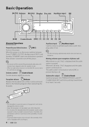
...call When there is a call . Subwoofer output Control knob Switches between Tuner ("TUNER"), CD ("CD"), Auxiliary input ("AUX"), and Standby ("STANDBY") each time pushing toward down for each ...(stereo) which does not have elapsed under the standby mode. • When an optional accessory is connected, the source name for at least 1 second to direct sunlight, excessive heat or...removed. Auxiliary input Auxiliary input Used to connect a portable audio device with your fingers. 4 | KMR-330 The audio system comes back on . When the call ends, "CALL" disappears and the audio system...
...call When there is a call . Subwoofer output Control knob Switches between Tuner ("TUNER"), CD ("CD"), Auxiliary input ("AUX"), and Standby ("STANDBY") each time pushing toward down for each ...(stereo) which does not have elapsed under the standby mode. • When an optional accessory is connected, the source name for at least 1 second to direct sunlight, excessive heat or...removed. Auxiliary input Auxiliary input Used to connect a portable audio device with your fingers. 4 | KMR-330 The audio system comes back on . When the call ends, "CALL" disappears and the audio system...
Owner's Manual (pdf)
Page 12
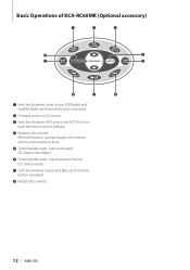
CD: Selects music. ¶ Switches between pause and play each time this button is pressed. ¢ Reduces the volume. Basic Operations of KCA-RC60MR (Optional accessory) „ … † ‹ ‡ ˆ ˆ ‰ Š ‰ ¡ Switches between tuner source (HD Radio) ... Tuner/Satellite radio: Selects the band. IN source each time this button is pressed again, the volume returns to CD source. £ Switches between AUX source and EXT. CD: Selects disc/folder. § Tuner/Satellite radio: Selects station/channel. When the button is pressed. • ...
CD: Selects music. ¶ Switches between pause and play each time this button is pressed. ¢ Reduces the volume. Basic Operations of KCA-RC60MR (Optional accessory) „ … † ‹ ‡ ˆ ˆ ‰ Š ‰ ¡ Switches between tuner source (HD Radio) ... Tuner/Satellite radio: Selects the band. IN source each time this button is pressed again, the volume returns to CD source. £ Switches between AUX source and EXT. CD: Selects disc/folder. § Tuner/Satellite radio: Selects station/channel. When the button is pressed. • ...
Owner's Manual (pdf)
Page 15
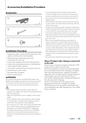
... connect the ignition wire (red) and the battery wire (yellow) to this unit. Use only the screws provided. If the receiver is 30° or less. To prevent a short circuit, do not connect the - connector to a rear output terminal....with vinyl tape or other control switch. English | 15 Accessories/Installation Procedure Accessories 1 ..........1 2 ..........2 3 ..........4 Installation Procedure 1. Connect the wiring harness wires in damage. Connecting unsupported disc changers/CD players to any Kenwood disc changers/ CD players released in turn may die. • If the...
... connect the ignition wire (red) and the battery wire (yellow) to this unit. Use only the screws provided. If the receiver is 30° or less. To prevent a short circuit, do not connect the - connector to a rear output terminal....with vinyl tape or other control switch. English | 15 Accessories/Installation Procedure Accessories 1 ..........1 2 ..........2 3 ..........4 Installation Procedure 1. Connect the wiring harness wires in damage. Connecting unsupported disc changers/CD players to any Kenwood disc changers/ CD players released in turn may die. • If the...
Owner's Manual (pdf)
Page 16
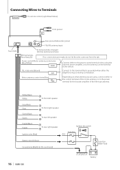
... ANT. CONT Depending on what antenna you are made, do not let the wire come out from the tab. Battery 16 | KMR-330 White/Black White To front left speaker Gray/Black Gray Green/Black Green To front right speaker To rear left speaker Purple/Black Purple ...Blue/Yellow) Front preout FRONT Fuse (10A) L Rear preout/Subwoofer preout R FM/AM antenna input Wiring harness (Accessory1) To Kenwood disc changer/ External optional accessory If no connections are using the optional power amplifier, or to the antenna control terminal in the vehicle. Power control/Motor antenna ...
... ANT. CONT Depending on what antenna you are made, do not let the wire come out from the tab. Battery 16 | KMR-330 White/Black White To front left speaker Gray/Black Gray Green/Black Green To front right speaker To rear left speaker Purple/Black Purple ...Blue/Yellow) Front preout FRONT Fuse (10A) L Rear preout/Subwoofer preout R FM/AM antenna input Wiring harness (Accessory1) To Kenwood disc changer/ External optional accessory If no connections are using the optional power amplifier, or to the antenna control terminal in the vehicle. Power control/Motor antenna ...

Owner's Manual (pdf)
Page 17
... removal tool toward the bottom, and pull out the unit halfway while pressing towards the inside. Bend the tabs of the mounting sleeve with the accessory screws. Removing the Unit 1 Refer to drop it may malfunction (for example, the sound may skip).
... removal tool toward the bottom, and pull out the unit halfway while pressing towards the inside. Bend the tabs of the mounting sleeve with the accessory screws. Removing the Unit 1 Refer to drop it may malfunction (for example, the sound may skip).


