Instruction Manual
Page 1
KAC-X522 STEREO/BRIDGEABLE POWER AMPLIFIER 7 page 2-9 INSTRUCTION MANUAL AMPLIFICATEUR DE PUISSANCE STEREO/COMPATIBLE 7 page 10-17 MODE D'EMPLOI ESTÉRO/AMPLIFICADOR DE POTENCIA CONECTABLE 7 página 18-25 MANUAL DE INSTRUCCIONES Take the time to the model and serial numbers whenever you obtain the best performance from your Kenwood dealer for information or...
KAC-X522 STEREO/BRIDGEABLE POWER AMPLIFIER 7 page 2-9 INSTRUCTION MANUAL AMPLIFICATEUR DE PUISSANCE STEREO/COMPATIBLE 7 page 10-17 MODE D'EMPLOI ESTÉRO/AMPLIFICADOR DE POTENCIA CONECTABLE 7 página 18-25 MANUAL DE INSTRUCCIONES Take the time to the model and serial numbers whenever you obtain the best performance from your Kenwood dealer for information or...
Instruction Manual
Page 2
... cloth. 2 CAUTION Do not wipe the panel with Canadian ICES-003. NOTE • If you of the speakers and then connect suitable speakers to the amplifier. 4Ω 4Ω 8 Ω 4Ω 4Ω 2 Ω Combined impedance 2 English They can scratch the surface of operation range. The ...and alcohol. Use it can control this equipment may cause burns if touched. If the "E-02" code does not disappear, contact your Kenwood dealer. Protection function There is generated to the speaker's output. When the unit has failed and direct current voltage is a Protection ...
... cloth. 2 CAUTION Do not wipe the panel with Canadian ICES-003. NOTE • If you of the speakers and then connect suitable speakers to the amplifier. 4Ω 4Ω 8 Ω 4Ω 4Ω 2 Ω Combined impedance 2 English They can scratch the surface of operation range. The ...and alcohol. Use it can control this equipment may cause burns if touched. If the "E-02" code does not disappear, contact your Kenwood dealer. Protection function There is generated to the speaker's output. When the unit has failed and direct current voltage is a Protection ...
Instruction Manual
Page 3
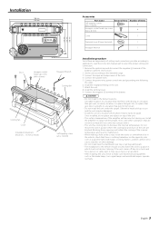
... such as a gasoline tank, brake pipe, or wiring harness, and be damaged. • Install this order. 6. Connect the negative - Install the amplifier in a location which it will inhibit the cooling of the units. 4. Attach the unit. 8. Connect the power wire, power control wire and grounding wire... the cooling fan and ducts of the unit are sensitive to heat will become hot during use. Install the terminal cover. 9. terminal of the amplifier will not come into contact with driving, In a location that gets wet, In a dusty location, In a place that gets hot, In ...
... such as a gasoline tank, brake pipe, or wiring harness, and be damaged. • Install this order. 6. Connect the negative - Install the amplifier in a location which it will inhibit the cooling of the units. 4. Attach the unit. 8. Connect the power wire, power control wire and grounding wire... the cooling fan and ducts of the unit are sensitive to heat will become hot during use. Install the terminal cover. 9. terminal of the amplifier will not come into contact with driving, In a location that gets wet, In a dusty location, In a place that gets hot, In ...
Instruction Manual
Page 4
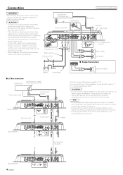
... same rating. • Check that the brake lamps, winkers, and wipers work properly. NOTE • The total length of the Master amplifier to a Slave amplifier, it is 14 meters (46 ft) maximum. Do not remove caps from the Center Unit. • If you assign the same ID... ■ Bridged Connections Battery Ground wire* Speaker (Bridged) ■ LX-Bus connection CENTER UNIT To Kenwood disc changer/ External optional accessory Power control wire Control cable (option) 30 30 Master amplifier Extension wire* 456 23 23 78 "0" 456 ID NUMBER 78 S-video cable* RCA cable* Set the...
... same rating. • Check that the brake lamps, winkers, and wipers work properly. NOTE • The total length of the Master amplifier to a Slave amplifier, it is 14 meters (46 ft) maximum. Do not remove caps from the Center Unit. • If you assign the same ID... ■ Bridged Connections Battery Ground wire* Speaker (Bridged) ■ LX-Bus connection CENTER UNIT To Kenwood disc changer/ External optional accessory Power control wire Control cable (option) 30 30 Master amplifier Extension wire* 456 23 23 78 "0" 456 ID NUMBER 78 S-video cable* RCA cable* Set the...
Instruction Manual
Page 5
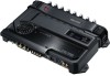
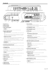
...) INPUT SENSITIVITY control Set this terminal. 7 ID NUMBER switch Sets an amp identification number (ID) to connect it as a high-power monaural amplifier. (The input right signal is turned On. The speakers to "LPF". % HPF FREQUENCY control Sets the cutoff frequency when the "FILTER" switch ... Center Unit. English 5 Assign ID Number "0" to the in the instruction manual of 2Ω or greater. Assign ID Numbers "1" to "7" to use as the Master amplifier. Controls 78 30 30 1 2 34 456 23 901 5 67 89 0 !@ # 1 Fuse (30 A × 2) 2 Battery terminal 3 Ground terminal 4 ...
...) INPUT SENSITIVITY control Set this terminal. 7 ID NUMBER switch Sets an amp identification number (ID) to connect it as a high-power monaural amplifier. (The input right signal is turned On. The speakers to "LPF". % HPF FREQUENCY control Sets the cutoff frequency when the "FILTER" switch ... Center Unit. English 5 Assign ID Number "0" to the in the instruction manual of 2Ω or greater. Assign ID Numbers "1" to "7" to use as the Master amplifier. Controls 78 30 30 1 2 34 456 23 901 5 67 89 0 !@ # 1 Fuse (30 A × 2) 2 Battery terminal 3 Ground terminal 4 ...
Instruction Manual
Page 6
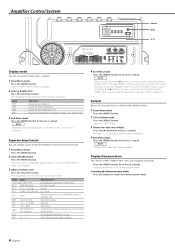
...follows. The setup items are displayed approximately 1 second first, then the set values are displayed repeatedly. Then, you can control sounds using the Amplifier Control function of the cooling fan in 3 steps: "FAST", "SLOW" or "OFF". 3 Exit Menu mode Press the [MENU] button...30C" is displayed. 2 Select a display item Press the [2] or [3] button. To call the Amplifier Control's values, hold down the [2] button 3 or more seconds during ID number display ("AMP"). Amplifier Control System FAN VOLT TEMP CURR Indicator MENU 2 / 3 Display mode You can register the values ...
...follows. The setup items are displayed approximately 1 second first, then the set values are displayed repeatedly. Then, you can control sounds using the Amplifier Control function of the cooling fan in 3 steps: "FAST", "SLOW" or "OFF". 3 Exit Menu mode Press the [MENU] button...30C" is displayed. 2 Select a display item Press the [2] or [3] button. To call the Amplifier Control's values, hold down the [2] button 3 or more seconds during ID number display ("AMP"). Amplifier Control System FAN VOLT TEMP CURR Indicator MENU 2 / 3 Display mode You can register the values ...
Instruction Manual
Page 7
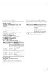
...OFFSET" -20 - 0 (dB) Volume offset "AMP NO"/ "AMP CONTROL NO" 0 - 7 Select an ID number of the unit is generated to the Kenwood's dealership. When the unit has failed and direct current voltage is overheating. "AMP × E-02"/"AMP × COND E-02" NOTE Turn the POWER switch ...release the protection. Select the "AMP NO"/"AMP CONTROL NO" display. "CURR" Indicates the current consumption (A). Messages that controlled by the Amplifier Control, the sound may be distorted due to ON, low frequency response is displayed and you are switched and displayed as that may be...
...OFFSET" -20 - 0 (dB) Volume offset "AMP NO"/ "AMP CONTROL NO" 0 - 7 Select an ID number of the unit is generated to the Kenwood's dealership. When the unit has failed and direct current voltage is overheating. "AMP × E-02"/"AMP × COND E-02" NOTE Turn the POWER switch ...release the protection. Select the "AMP NO"/"AMP CONTROL NO" display. "CURR" Indicates the current consumption (A). Messages that controlled by the Amplifier Control, the sound may be distorted due to ON, low frequency response is displayed and you are switched and displayed as that may be...
Instruction Manual
Page 9
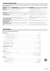
.../oct.)...50 - 200 Hz (variable) Infrasonic Filter Frequency (24 dB/oct.)...15 Hz Frequency Response (+0, -3 dB)...5 Hz - 70 kHz Signal to Noise Ratio...105 dB Amplifier Control Section (EQ) Bass frequency ...60 / 80 / 100 / 200 Hz Bass level ...-15 - +15 dB Bass Q factor...1.00 / 1.25 / 1.50 / 2....8226; Protection circuit may be set improperly. • The AMP CONT has been turned "OFF". • The filtered band has been controlled by the Amplifier Control of the unit. SOLUTION • Connect the input (or output) cables. • Check connections by referring to . • Replace the ...
.../oct.)...50 - 200 Hz (variable) Infrasonic Filter Frequency (24 dB/oct.)...15 Hz Frequency Response (+0, -3 dB)...5 Hz - 70 kHz Signal to Noise Ratio...105 dB Amplifier Control Section (EQ) Bass frequency ...60 / 80 / 100 / 200 Hz Bass level ...-15 - +15 dB Bass Q factor...1.00 / 1.25 / 1.50 / 2....8226; Protection circuit may be set improperly. • The AMP CONT has been turned "OFF". • The filtered band has been controlled by the Amplifier Control of the unit. SOLUTION • Connect the input (or output) cables. • Check connections by referring to . • Replace the ...


