Instruction Manual
Page 1
For your Kenwood dealer for information or service on the warranty card, and in the space provided below. Refer to read through this instruction manual. Model KAC-X522 Serial number US Residence Only Register Online Register your new power amplifier. Familiarity with installation and operation ...procedures will help you call upon your records Record the serial number, found on the back of the unit, in the spaces designated on the product. KAC-X522 STEREO/BRIDGEABLE POWER AMPLIFIER 7 page 2-9 ...
For your Kenwood dealer for information or service on the warranty card, and in the space provided below. Refer to read through this instruction manual. Model KAC-X522 Serial number US Residence Only Register Online Register your new power amplifier. Familiarity with installation and operation ...procedures will help you call upon your records Record the serial number, found on the back of the unit, in the spaces designated on the product. KAC-X522 STEREO/BRIDGEABLE POWER AMPLIFIER 7 page 2-9 ...
Instruction Manual
Page 2
...the panel and/or cause the indicator letters to peel off the power immediately and consult your Kenwood dealer. • Do not touch the unit during installation, consult your unit to operate this unit directly from various problems. When Protection operates, the ...display informs you experience problems during use radio frequency energy. If the "E-02" code does not disappear, contact your Kenwood dealer. terminal. Safety precautions...
...the panel and/or cause the indicator letters to peel off the power immediately and consult your Kenwood dealer. • Do not touch the unit during installation, consult your unit to operate this unit directly from various problems. When Protection operates, the ...display informs you experience problems during use radio frequency energy. If the "E-02" code does not disappear, contact your Kenwood dealer. terminal. Safety precautions...
Instruction Manual
Page 3
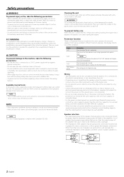
...0˃ OFF OFF 15Hz Ø6 Duct Hexagon socket Hexagon Wrench head cap screw (M4 × 8 mm) Cooling fan Cooling fan Cover Installation board, etc. (thickness : 15 mm or more) Self-tapping screw (ø5 × 18 mm) Accessories Part name Self-tapping screws ...cap screw (M4 × 8 mm) External View Number of Items 4 4 Cover 1 Terminal cover (Power terminal) 1 Hexagon Wrench 1 Installation procedure Since there are blocked. Connect the speaker wires. 5. terminal of settings and connections possible according to applications, read the instruction manual well ...
...0˃ OFF OFF 15Hz Ø6 Duct Hexagon socket Hexagon Wrench head cap screw (M4 × 8 mm) Cooling fan Cooling fan Cover Installation board, etc. (thickness : 15 mm or more) Self-tapping screw (ø5 × 18 mm) Accessories Part name Self-tapping screws ...cap screw (M4 × 8 mm) External View Number of Items 4 4 Cover 1 Terminal cover (Power terminal) 1 Hexagon Wrench 1 Installation procedure Since there are blocked. Connect the speaker wires. 5. terminal of settings and connections possible according to applications, read the instruction manual well ...
Instruction Manual
Page 4
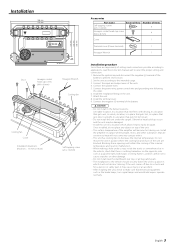
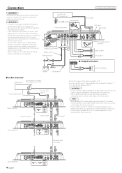
...speaker connectors separately. You must connect any of them . 2 CAUTION • Do not connect 2 Master amplifiers to fail. • After installation, check that no unconnected wires or connectors are touching the car body. Do not remove caps from the Center Unit. • If you ... terminal Right speaker Left speaker ■ Bridged Connections Battery Ground wire* Speaker (Bridged) ■ LX-Bus connection CENTER UNIT To Kenwood disc changer/ External optional accessory Power control wire Control cable (option) 30 30 Master amplifier Extension wire* 456 23 23 78 "0"...
...speaker connectors separately. You must connect any of them . 2 CAUTION • Do not connect 2 Master amplifiers to fail. • After installation, check that no unconnected wires or connectors are touching the car body. Do not remove caps from the Center Unit. • If you ... terminal Right speaker Left speaker ■ Bridged Connections Battery Ground wire* Speaker (Bridged) ■ LX-Bus connection CENTER UNIT To Kenwood disc changer/ External optional accessory Power control wire Control cable (option) 30 30 Master amplifier Extension wire* 456 23 23 78 "0"...
Instruction Manual
Page 9
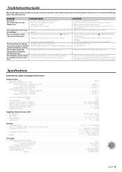
... V allowable) Current Consumption (+B = 12.0 V, 1 kHz, 10 % THD, 4 Ω)...37 A Dimensions (W × H × D) ...386 × 61 × 259.5 mm ...15-3/16 × 2-3/8 × 10-3/16 inch Installation Size (W × H × D) ...386 × 61 × 265 mm ...15-3/16 × 2-3/8 × 10-3/8 inch Weight ...3.83 kg (8.44 lbs) CEA-2006 RMS Power Output...
... V allowable) Current Consumption (+B = 12.0 V, 1 kHz, 10 % THD, 4 Ω)...37 A Dimensions (W × H × D) ...386 × 61 × 259.5 mm ...15-3/16 × 2-3/8 × 10-3/16 inch Installation Size (W × H × D) ...386 × 61 × 265 mm ...15-3/16 × 2-3/8 × 10-3/8 inch Weight ...3.83 kg (8.44 lbs) CEA-2006 RMS Power Output...


