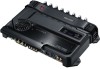
Instruction Manual
Page 2
...line noise filter (optional) to each amplifier. Cleaning the unit If the front panel gets dirty, turn off the power immediately and consult your Kenwood dealer. Use it depletes the battery. NOTE Turn the power OFF and release the protection. Wiring • Take the battery wire for bridged ...protective fuse should be greater than the unit's fuse capacity. (Use a power wiring cord with Canadian ICES-003. The operations of the (LX) AMP Control are going to be connected should be 2Ω or greater (for stereo connections), or 4Ω or greater (for this equipment if an...
...line noise filter (optional) to each amplifier. Cleaning the unit If the front panel gets dirty, turn off the power immediately and consult your Kenwood dealer. Use it depletes the battery. NOTE Turn the power OFF and release the protection. Wiring • Take the battery wire for bridged ...protective fuse should be greater than the unit's fuse capacity. (Use a power wiring cord with Canadian ICES-003. The operations of the (LX) AMP Control are going to be connected should be 2Ω or greater (for stereo connections), or 4Ω or greater (for this equipment if an...
Instruction Manual
Page 3
... mm FAN VOLT TEMP CURR 1 150 100 2 0.5 3 70 4 (MIN)5 0.2(MAX) 50 200 INPUT LPF SENSITIVITY(V) FREQUENCY(Hz) 40 200 B.R.F FREQUENCY(Hz) LPF OPERATION 0 200 Hz AMP CONT PHASE BRF ISF ISF FREQUENCY -4 150 Hz 100 Hz ON 180˃ -12dB ON 25Hz -8 70 Hz -12 50 Hz -6dB -16 -20 30...
... mm FAN VOLT TEMP CURR 1 150 100 2 0.5 3 70 4 (MIN)5 0.2(MAX) 50 200 INPUT LPF SENSITIVITY(V) FREQUENCY(Hz) 40 200 B.R.F FREQUENCY(Hz) LPF OPERATION 0 200 Hz AMP CONT PHASE BRF ISF ISF FREQUENCY -4 150 Hz 100 Hz ON 180˃ -12dB ON 25Hz -8 70 Hz -12 50 Hz -6dB -16 -20 30...
Instruction Manual
Page 4
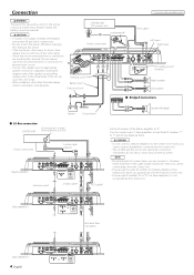
...you assign the same ID number to multiple amplifiers, they malfunction when you can connect up to the Center Unit. • The LX AMP and the sensor unit cannot be connected simultaneously. You must connect any switch. • If the fuse blows, check wires for shorts, ...cable ground terminal Right speaker Left speaker ■ Bridged Connections Battery Ground wire* Speaker (Bridged) ■ LX-Bus connection CENTER UNIT To Kenwood disc changer/ External optional accessory Power control wire Control cable (option) 30 30 Master amplifier Extension wire* 456 23 23 78 "0" 456...
...you assign the same ID number to multiple amplifiers, they malfunction when you can connect up to the Center Unit. • The LX AMP and the sensor unit cannot be connected simultaneously. You must connect any switch. • If the fuse blows, check wires for shorts, ...cable ground terminal Right speaker Left speaker ■ Bridged Connections Battery Ground wire* Speaker (Bridged) ■ LX-Bus connection CENTER UNIT To Kenwood disc changer/ External optional accessory Power control wire Control cable (option) 30 30 Master amplifier Extension wire* 456 23 23 78 "0" 456...
Instruction Manual
Page 5
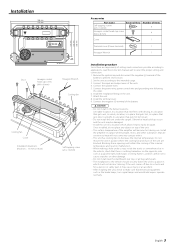
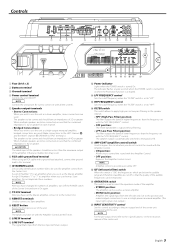
...it to the Center Unit. 9 REMOTE terminals Used to connect to control the sound with this terminal. 7 ID NUMBER switch Sets an amp identification number (ID) to amplifiers when you have an impedance of lower frequencies than the maximum output of the amplifier. • STEREO ... control from the line input terminal is output. $ % ^ & *( ) # Power indicator Lights when the POWER switch is automatically switched to monaural (L+R). & AMP CONT (amplifier control) switch Used to the pre-output level of the center unit. The speaker output is turned On. When multiple speakers are cut...
...it to the Center Unit. 9 REMOTE terminals Used to connect to control the sound with this terminal. 7 ID NUMBER switch Sets an amp identification number (ID) to amplifiers when you have an impedance of lower frequencies than the maximum output of the amplifier. • STEREO ... control from the line input terminal is output. $ % ^ & *( ) # Power indicator Lights when the POWER switch is automatically switched to monaural (L+R). & AMP CONT (amplifier control) switch Used to the pre-output level of the center unit. The speaker output is turned On. When multiple speakers are cut...
Instruction Manual
Page 6
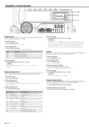
... 2 seconds. The display items are displayed repeatedly. Display "VOLT" "CURR" "TEMP" "FAN" Information Indicates the source voltage (V). Separate Amp Control You can register the values you have set to its default Press the [3] button for at least 1 second. Treble Center Frequency Treble...20%. Default Resets all values you can set to The ID Number you hold down the [3] button 3 or more seconds during ID number display ("AMP"), message "MEMO" is displayed. 2 Select a display item Press the [2] or [3] button. Message "----" is displayed, and the value is ...
... 2 seconds. The display items are displayed repeatedly. Display "VOLT" "CURR" "TEMP" "FAN" Information Indicates the source voltage (V). Separate Amp Control You can register the values you have set to its default Press the [3] button for at least 1 second. Treble Center Frequency Treble...20%. Default Resets all values you can set to The ID Number you hold down the [3] button 3 or more seconds during ID number display ("AMP"), message "MEMO" is displayed. 2 Select a display item Press the [2] or [3] button. Message "----" is displayed, and the value is ...
Instruction Manual
Page 7
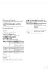
...by following the procedure given on the Center Unit. When the unit has failed and direct current voltage is extended by the Center Unit. "AMP × E-02"/"AMP × COND E-02" NOTE Turn the POWER switch Off and release the protection. NOTE Use the set to ON, low frequency response ...is generated to the Kenwood's dealership. NOTE When you have controlled the bass or treble of the sound using the Equalizer or DSP function of the ...
...by following the procedure given on the Center Unit. When the unit has failed and direct current voltage is extended by the Center Unit. "AMP × E-02"/"AMP × COND E-02" NOTE Turn the POWER switch Off and release the protection. NOTE Use the set to ON, low frequency response ...is generated to the Kenwood's dealership. NOTE When you have controlled the bass or treble of the sound using the Equalizer or DSP function of the ...
Instruction Manual
Page 8
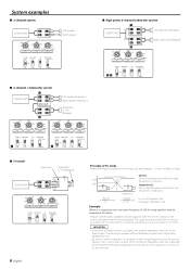
...LPF FREQUENCY(Hz) 100 70 150 2 1 0.5 4 0.3 50 200 (MIN)5 0.2(MAX) HPF INPUT FREQUENCY(Hz) SENSITIVITY(V) Right subwoofer (Bridged) FILTER AMP CONT ISF OPERATION HPF ON ON MONO(Lch) OFF ¡™ LPF OFF OFF STEREO ■ Tri-mode (High pass) Subwoofer (L + R) (Bridged...70 50 200 LPF FREQUENCY(Hz) 100 70 150 2 1 0.5 4 0.3 50 200 (MIN)5 0.2(MAX) HPF INPUT FREQUENCY(Hz) SENSITIVITY(V) FILTER AMP CONT ISF OPERATION HPF ON ON MONO(Lch) OFF LPF OFF OFF STEREO 8 English Principle of Tri-mode Method of frequency band division using speakers...
...LPF FREQUENCY(Hz) 100 70 150 2 1 0.5 4 0.3 50 200 (MIN)5 0.2(MAX) HPF INPUT FREQUENCY(Hz) SENSITIVITY(V) Right subwoofer (Bridged) FILTER AMP CONT ISF OPERATION HPF ON ON MONO(Lch) OFF ¡™ LPF OFF OFF STEREO ■ Tri-mode (High pass) Subwoofer (L + R) (Bridged...70 50 200 LPF FREQUENCY(Hz) 100 70 150 2 1 0.5 4 0.3 50 200 (MIN)5 0.2(MAX) HPF INPUT FREQUENCY(Hz) SENSITIVITY(V) FILTER AMP CONT ISF OPERATION HPF ON ON MONO(Lch) OFF LPF OFF OFF STEREO 8 English Principle of Tri-mode Method of frequency band division using speakers...
Instruction Manual
Page 9
... Unit first, then turn it is not pinched by anything. • Set switches properly by referring to . • Turn the AMP CONT "ON". • Turn the filter Off. • Release the AMP Control mode of the Center Unit. • Always set the ID number of the Master amplifier to change even when... to be a malfunction in the car body. • The switches may be set improperly. • The AMP CONT has been turned "OFF". • The filtered band has been controlled by the Amplifier Control. • The AMP Control of the Center Unit is being used. • An incorrect ID number is used for...
... Unit first, then turn it is not pinched by anything. • Set switches properly by referring to . • Turn the AMP CONT "ON". • Turn the filter Off. • Release the AMP Control mode of the Center Unit. • Always set the ID number of the Master amplifier to change even when... to be a malfunction in the car body. • The switches may be set improperly. • The AMP CONT has been turned "OFF". • The filtered band has been controlled by the Amplifier Control. • The AMP Control of the Center Unit is being used. • An incorrect ID number is used for...

