Instruction Manual
Page 1
... www.kenwoodusa.com © B64-3394-00/00 (KV) For your Kenwood dealer for information or service on the warranty card, and in the spaces designated on the product. Model KAC-X522 Serial number US Residence Only Register Online Register your new power amplifier. Familiarity with installation and operation procedures will help you call...
... www.kenwoodusa.com © B64-3394-00/00 (KV) For your Kenwood dealer for information or service on the warranty card, and in the spaces designated on the product. Model KAC-X522 Serial number US Residence Only Register Online Register your new power amplifier. Familiarity with installation and operation procedures will help you call...
Instruction Manual
Page 2
...01" "E-02" "E-03" "VOLT" display is generated to the speaker's output. NOTE Turn the power OFF and release the protection. When the speaker cord is overheating. Available Control Units: A Kenwood's LX-Bus supporting Center Unit released in the ACC ON position without turning the engine ON, it...; To prevent a short circuit, never put or leave any of the panel and/or cause the indicator letters to peel off the power immediately and consult your Kenwood dealer. If the "E-02" code does not disappear, contact your unit to malfunction. • To prevent a short circuit when replacing...
...01" "E-02" "E-03" "VOLT" display is generated to the speaker's output. NOTE Turn the power OFF and release the protection. When the speaker cord is overheating. Available Control Units: A Kenwood's LX-Bus supporting Center Unit released in the ACC ON position without turning the engine ON, it...; To prevent a short circuit, never put or leave any of the panel and/or cause the indicator letters to peel off the power immediately and consult your Kenwood dealer. If the "E-02" code does not disappear, contact your unit to malfunction. • To prevent a short circuit when replacing...
Instruction Manual
Page 3
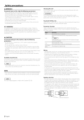
Remove the ignition key and disconnect the negative - terminal of the battery to the intended usage. 3. Connect the power wire, power control wire and grounding wire following this unit in a place where the cooling fan and ducts of the unit are blocked. Connect ...-tapping screws (ø5 × 18 mm) Hexagon socket head cap screw (M4 × 8 mm) External View Number of Items 4 4 Cover 1 Terminal cover (Power terminal) 1 Hexagon Wrench 1 Installation procedure Since there are sensitive to heat will not come into contact with driving, In a location that gets wet, In a dusty...
Remove the ignition key and disconnect the negative - terminal of the battery to the intended usage. 3. Connect the power wire, power control wire and grounding wire following this unit in a place where the cooling fan and ducts of the unit are blocked. Connect ...-tapping screws (ø5 × 18 mm) Hexagon socket head cap screw (M4 × 8 mm) External View Number of Items 4 4 Cover 1 Terminal cover (Power terminal) 1 Hexagon Wrench 1 Installation procedure Since there are sensitive to heat will not come into contact with driving, In a location that gets wet, In a dusty...
Instruction Manual
Page 4
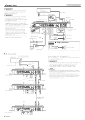
... CAUTION CENTER UNIT (CD receiver, etc.) Lead terminal* • If sound is not output normally, immediately turn power off and check connections. • Be sure to turn the power off before changing the setting of any of them . 2 CAUTION • Do not connect 2 Master amplifiers to... speaker Left speaker ■ Bridged Connections Battery Ground wire* Speaker (Bridged) ■ LX-Bus connection CENTER UNIT To Kenwood disc changer/ External optional accessory Power control wire Control cable (option) 30 30 Master amplifier Extension wire* 456 23 23 78 "0" 456 ID NUMBER 78...
... CAUTION CENTER UNIT (CD receiver, etc.) Lead terminal* • If sound is not output normally, immediately turn power off and check connections. • Be sure to turn the power off before changing the setting of any of them . 2 CAUTION • Do not connect 2 Master amplifiers to... speaker Left speaker ■ Bridged Connections Battery Ground wire* Speaker (Bridged) ■ LX-Bus connection CENTER UNIT To Kenwood disc changer/ External optional accessory Power control wire Control cable (option) 30 30 Master amplifier Extension wire* 456 23 23 78 "0" 456 ID NUMBER 78...
Instruction Manual
Page 5
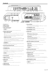
... position: The entire bandwidth is 2Ω or greater for amplifier control from the line input terminal is output. $ % ^ & *( ) # Power indicator Lights when the POWER switch is 4Ω or greater. 2 CAUTION The rated input of the unit. English 5 Controls 78 30 30 1 2 34 456 23 901 ...5 67 89 0 !@ # 1 Fuse (30 A × 2) 2 Battery terminal 3 Ground terminal 4 Power control terminal Controls the unit ON/OFF. LINE IN terminal @ LINE OUT terminal The signal that the combined impedance is output without filtering. • LPF...
... position: The entire bandwidth is 2Ω or greater for amplifier control from the line input terminal is output. $ % ^ & *( ) # Power indicator Lights when the POWER switch is 4Ω or greater. 2 CAUTION The rated input of the unit. English 5 Controls 78 30 30 1 2 34 456 23 901 ...5 67 89 0 !@ # 1 Fuse (30 A × 2) 2 Battery terminal 3 Ground terminal 4 Power control terminal Controls the unit ON/OFF. LINE IN terminal @ LINE OUT terminal The signal that the combined impedance is output without filtering. • LPF...
Instruction Manual
Page 7
... on the Center Unit When you are switched and displayed as that controlled by the Amplifier Control, the sound may be distorted due to the Kenwood's dealership. "VOLT" Indicates the source voltage (V). NOTE When you have controlled the bass or treble of the sound using the Equalizer or DSP ...adjustment Select the desired set items. 3 Set an ID number of the Center Unit. "AMP × E-02"/"AMP × COND E-02" NOTE Turn the POWER switch Off and release the protection. "AMP × E-03"/"AMP × COND E-03" When the speaker cord is in the Standby mode. You can ...
... on the Center Unit When you are switched and displayed as that controlled by the Amplifier Control, the sound may be distorted due to the Kenwood's dealership. "VOLT" Indicates the source voltage (V). NOTE When you have controlled the bass or treble of the sound using the Equalizer or DSP ...adjustment Select the desired set items. 3 Set an ID number of the Center Unit. "AMP × E-02"/"AMP × COND E-02" NOTE Turn the POWER switch Off and release the protection. "AMP × E-03"/"AMP × COND E-03" When the speaker cord is in the Standby mode. You can ...
Instruction Manual
Page 8
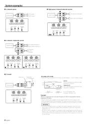
...(Lch) ¡ OFF LPF OFF OFF STEREO FILTER AMP CONT ISF OPERATION HPF ON ON MONO(Lch) OFF ™ LPF OFF OFF STEREO ■ High-power 2-channel subwoofer system ¡ L L L CENTER UNIT RR Left subwoofer (Bridged) R L L RR ™ 150 100 70 50 200 LPF FREQUENCY(Hz) 100 70 150 2 1 0.5 4 0.3 50 200...
...(Lch) ¡ OFF LPF OFF OFF STEREO FILTER AMP CONT ISF OPERATION HPF ON ON MONO(Lch) OFF ™ LPF OFF OFF STEREO ■ High-power 2-channel subwoofer system ¡ L L L CENTER UNIT RR Left subwoofer (Bridged) R L L RR ™ 150 100 70 50 200 LPF FREQUENCY(Hz) 100 70 150 2 1 0.5 4 0.3 50 200...
Instruction Manual
Page 9
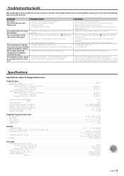
...to change even when you have changed the ID number of an amplifier, turn Off the POWER switch of the Center Unit first, then turn it On again. Audio Section Max Power Output...1000 W Rated Power Output (+B = 12.0 V) Normal (4 Ω) (20 Hz - 20 kHz, 0....05 % THD)...80 W × 2 Normal (2 Ω) (1 kHz, 0.5 % THD) ...160 W × 2 Bridged (4 Ω) (1 kHz, 0.5 % THD)...320 W × 1 Rated Power Output (+B = 14.4 V) Normal (4 Ω) (20 Hz - 20 kHz, 0.05 % THD)...125 W × 2 Normal (2 Ω) (1 kHz, 0.5 % THD) ...250 W × 2 Bridged (4 Ω) (1 kHz,...
...to change even when you have changed the ID number of an amplifier, turn Off the POWER switch of the Center Unit first, then turn it On again. Audio Section Max Power Output...1000 W Rated Power Output (+B = 12.0 V) Normal (4 Ω) (20 Hz - 20 kHz, 0....05 % THD)...80 W × 2 Normal (2 Ω) (1 kHz, 0.5 % THD) ...160 W × 2 Bridged (4 Ω) (1 kHz, 0.5 % THD)...320 W × 1 Rated Power Output (+B = 14.4 V) Normal (4 Ω) (20 Hz - 20 kHz, 0.05 % THD)...125 W × 2 Normal (2 Ω) (1 kHz, 0.5 % THD) ...250 W × 2 Bridged (4 Ω) (1 kHz,...


