
Instruction Manual
Page 1
... installation and operation procedures will help you call upon your KENWOOD dealer for information or service on the warranty card, and in the space provided below. Refer to read through this instruction manual. Model KRC-108S Serial number © B64-1540-00 (KW) For your new cassette-receiver. KRC-108S CASSETTE RECEIVER INSTRUCTION MANUAL AMPLI-TUNER-LECTEUR DE CASSETTE MODE D'EMPLOI RADIO CASETE MANUAL DE INSTRUCCIONES RADIO CASSETE MANUAL DE INSTRUÇÕES Take the time...
... installation and operation procedures will help you call upon your KENWOOD dealer for information or service on the warranty card, and in the space provided below. Refer to read through this instruction manual. Model KRC-108S Serial number © B64-1540-00 (KW) For your new cassette-receiver. KRC-108S CASSETTE RECEIVER INSTRUCTION MANUAL AMPLI-TUNER-LECTEUR DE CASSETTE MODE D'EMPLOI RADIO CASETE MANUAL DE INSTRUCCIONES RADIO CASSETE MANUAL DE INSTRUÇÕES Take the time...

Instruction Manual
Page 2
... Contents Before use Safety precautions 3 General features Power 5 Switching Modes 5 Volume 6 Attenuator 6 Loudness 6 Audio Control Setting 6 ec4/dB (Sound Coordinate 7 Clock display 7 Adjusting Time 7 Tuner features Tuning 8 Station Preset Memory 8 Auto Memory Entry 9 Clean Reception System Circuit (CRSC 9 Cassette player features Playing Cassette Tapes 10 Fast Forwarding and Rewinding Cassette Tapes 10 Tuner Call 11 Installation Accessories 12 Installation Procedure 12 Connecting Wires to Terminals 13 Installation 14 Troubleshooting guide 16 Specifications 17 -2-
... Contents Before use Safety precautions 3 General features Power 5 Switching Modes 5 Volume 6 Attenuator 6 Loudness 6 Audio Control Setting 6 ec4/dB (Sound Coordinate 7 Clock display 7 Adjusting Time 7 Tuner features Tuning 8 Station Preset Memory 8 Auto Memory Entry 9 Clean Reception System Circuit (CRSC 9 Cassette player features Playing Cassette Tapes 10 Fast Forwarding and Rewinding Cassette Tapes 10 Tuner Call 11 Installation Accessories 12 Installation Procedure 12 Connecting Wires to Terminals 13 Installation 14 Troubleshooting guide 16 Specifications 17 -2-

Instruction Manual
Page 3
... ignition, battery, or ground wires, make sure to use your health or even fatal. The liquid crystal fluid may cause your unit to malfunction. • To prevent a short circuit when replacing a fuse, first disconnect the wiring harness. • Do not use automotivegrade wires or other wires with too much dust or the possibility of water splashing. • Do not subject the faceplate to...
... ignition, battery, or ground wires, make sure to use your health or even fatal. The liquid crystal fluid may cause your unit to malfunction. • To prevent a short circuit when replacing a fuse, first disconnect the wiring harness. • Do not use automotivegrade wires or other wires with too much dust or the possibility of water splashing. • Do not subject the faceplate to...
Instruction Manual
Page 4
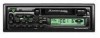
... not solve the problem, consult your Kenwood dealer. • If the unit does not seem to operate this manual are examples used to malfunction. • Do not leave tapes in the instruction manual. KRC-108S Reset button • Characters in the LCD may cause harmful interference unless the modifications are used. They can cause the unit to explain more clearly how the controls are expressly...
... not solve the problem, consult your Kenwood dealer. • If the unit does not seem to operate this manual are examples used to malfunction. • Do not leave tapes in the instruction manual. KRC-108S Reset button • Characters in the LCD may cause harmful interference unless the modifications are used. They can cause the unit to explain more clearly how the controls are expressly...
Instruction Manual
Page 5
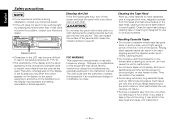
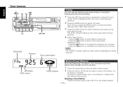
..." is displayed, the standby mode is activated. NOTE Turn the power on the power: Press the SRC (source) button. Use this mode when you press the SRC (source) button, the mode switches as follows: M Tuner mode M Tape mode M Standby mode Selecting standby mode: Press the SRC button repeatedly and switch to the unit on. NOTE The mode switches to anything. General features SRC / PWR OFF u ATT/LOUD 4 ¢ CLK d #1~5 AUD BAND ATT indicator LOUD indicator Power Turning on before...
..." is displayed, the standby mode is activated. NOTE Turn the power on the power: Press the SRC (source) button. Use this mode when you press the SRC (source) button, the mode switches as follows: M Tuner mode M Tape mode M Standby mode Selecting standby mode: Press the SRC button repeatedly and switch to the unit on. NOTE The mode switches to anything. General features SRC / PWR OFF u ATT/LOUD 4 ¢ CLK d #1~5 AUD BAND ATT indicator LOUD indicator Power Turning on before...
Instruction Manual
Page 6
... volume. "BL": Adjust the balance level. Setting values: Left 15 - Attenuator This function allows you use that source ( for example, FM mode uses the tone settings made for a particular source are recalled automatically whenever you to turn down . Turning Attenuator On/Off: Press the ATT button to switch the attenuator on . The settings made for FM, AM for the adjusting values. 4 Press the AUD button to end the control mode. Loudness This function amplifies...
... volume. "BL": Adjust the balance level. Setting values: Left 15 - Attenuator This function allows you use that source ( for example, FM mode uses the tone settings made for a particular source are recalled automatically whenever you to turn down . Turning Attenuator On/Off: Press the ATT button to switch the attenuator on . The settings made for FM, AM for the adjusting values. 4 Press the AUD button to end the control mode. Loudness This function amplifies...
Instruction Manual
Page 7
... the best audio setting preset for at least two seconds to end the sound coordinate mode. bass center frequency, bass level, bass quality factor, bass extension, treble center frequency, and treble level setting. Rear 15 ec4/dB (Sound Coordinate) You can call the following settings with this function; Adjusting Time Adjust the time. 1 When the time is not displayed, first press the CLK button to display the time. 2 Press the CLK button for different types of the bass and treble tones are...
... the best audio setting preset for at least two seconds to end the sound coordinate mode. bass center frequency, bass level, bass quality factor, bass extension, treble center frequency, and treble level setting. Rear 15 ec4/dB (Sound Coordinate) You can call the following settings with this function; Adjusting Time Adjust the time. 1 When the time is not displayed, first press the CLK button to display the time. 2 Press the CLK button for different types of the bass and treble tones are...
Instruction Manual
Page 8
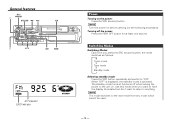
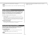
.... Each time you want to use for the station, for the desired station. -8- English Tuner features SRC / BAND / PWR OFF 4 ¢ CRSC #1~6 AUTO / AME KRC-108S Band display Frequency Preset station number Tuning You can then recall that station with a single touch of a button. 1 Select the band/ station that you press the BAND button, the band switches between FM1, FM2, FM3, and AM. 3 Press the AUTO button to switch between auto seek tuning of receivable frequencies and manual tuning...
.... Each time you want to use for the station, for the desired station. -8- English Tuner features SRC / BAND / PWR OFF 4 ¢ CRSC #1~6 AUTO / AME KRC-108S Band display Frequency Preset station number Tuning You can then recall that station with a single touch of a button. 1 Select the band/ station that you press the BAND button, the band switches between FM1, FM2, FM3, and AM. 3 Press the AUTO button to switch between auto seek tuning of receivable frequencies and manual tuning...
Instruction Manual
Page 9
... second to start auto memory entry. Turning CRSC On/Off: Press the CRSC button for the desired station. The indicator lights up when CRSC is displayed. Up to the FM station. The numbers of the preset station buttons are available. In such a situation, turn the function on . This function is turned on /off . The tuner then plays the last station received. NOTE Strong electrical fields (such as from stereo to mono...
... second to start auto memory entry. Turning CRSC On/Off: Press the CRSC button for the desired station. The indicator lights up when CRSC is displayed. Up to the FM station. The numbers of the preset station buttons are available. In such a situation, turn the function on . This function is turned on /off . The tuner then plays the last station received. NOTE Strong electrical fields (such as from stereo to mono...
Instruction Manual
Page 10
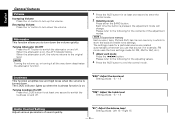
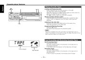
... displayed when the tape mode has been selected. The tape stops playing and the cassette ejects. Rewinding Tapes: Press the REW button. With side A facing up, the 3 indicator lights up while play will begin . - 10 - If the FF button is pressed, normal tape play is being fast forwarded. English Cassette player features SRC / PWR OFF 0 T.CALL T.CALL indicator REW FF KRC-108S Playing Cassette Tapes Loading and Playing Cassettes: Load a cassette...
... displayed when the tape mode has been selected. The tape stops playing and the cassette ejects. Rewinding Tapes: Press the REW button. With side A facing up, the 3 indicator lights up while play will begin . - 10 - If the FF button is pressed, normal tape play is being fast forwarded. English Cassette player features SRC / PWR OFF 0 T.CALL T.CALL indicator REW FF KRC-108S Playing Cassette Tapes Loading and Playing Cassettes: Load a cassette...

Instruction Manual
Page 11
The T.CALL indicator lights up when tuner call on . - 11 - Turning Tuner Call On/Off: Press the T.CALL button to the tuner while you are rewinding or fast forwarding the tape. Tuner Call Switch automatically to switch tuner call is turned on and off.
The T.CALL indicator lights up when tuner call on . - 11 - Turning Tuner Call On/Off: Press the T.CALL button to the tuner while you are rewinding or fast forwarding the tape. Tuner Call Switch automatically to switch tuner call is turned on and off.
Instruction Manual
Page 12
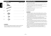
... fuse blows, first make sure to which they correspond. If you connect the ignition wire to a power source with a constant voltage supply, as shown above. battery. 2. Connect the wiring harness wires in the car. • After the unit is installed, check whether the brake lamps, blinkers, wipers, etc. Press the reset button. 2CAUTION • If your car. 7. on and off with battery wires, the battery may be turned on the car are working...
... fuse blows, first make sure to which they correspond. If you connect the ignition wire to a power source with a constant voltage supply, as shown above. battery. 2. Connect the wiring harness wires in the car. • After the unit is installed, check whether the brake lamps, blinkers, wipers, etc. Press the reset button. 2CAUTION • If your car. 7. on and off with battery wires, the battery may be turned on the car are working...
Instruction Manual
Page 13
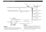
...; R Purple To rear left speaker to the car chassis (ground), you connect the ignition wire (red) and the battery wire (yellow) to a front output terminal, do not connect the - Connecting Wires to Terminals Fuse (10A) FM/AM antenna input If no connections are being connected to the system, connect the connectors either to the power control terminal when using the optional power amplifier, or to the power source running through the fuse box. connector to a rear output terminal. - 13...
...; R Purple To rear left speaker to the car chassis (ground), you connect the ignition wire (red) and the battery wire (yellow) to a front output terminal, do not connect the - Connecting Wires to Terminals Fuse (10A) FM/AM antenna input If no connections are being connected to the system, connect the connectors either to the power control terminal when using the optional power amplifier, or to the power source running through the fuse box. connector to a rear output terminal. - 13...
Instruction Manual
Page 14
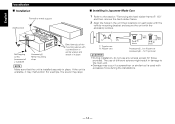
I Installation Firewall or metal support Accessory4 Self-tapping screw (commerciall y available) Accessory2 Metal mounting strap Bend the tabs of different screws might result in the unit (two locations on each side) with the vehicle mounting bracket and secure the unit with excessive force during the installations. - 14 - Accessory5...for Nissan car Accessory6 ...for Toyota car 2CAUTION • During installation, do not use of...
I Installation Firewall or metal support Accessory4 Self-tapping screw (commerciall y available) Accessory2 Metal mounting strap Bend the tabs of different screws might result in the unit (two locations on each side) with the vehicle mounting bracket and secure the unit with excessive force during the installations. - 14 - Accessory5...for Nissan car Accessory6 ...for Toyota car 2CAUTION • During installation, do not use of...

Instruction Manual
Page 15
... top side in the figure. Catch facing up Accessory3 Removal tool NOTE The frame can be removed from the catch pins on the removal tool. 5 Pull the unit all the way out with integral washer (M4×8) on the back panel. 3 Insert the two removal tools deeply into the slots on the lower level. Lower the frame and pull...
... top side in the figure. Catch facing up Accessory3 Removal tool NOTE The frame can be removed from the catch pins on the removal tool. 5 Pull the unit all the way out with integral washer (M4×8) on the back panel. 3 Insert the two removal tools deeply into the slots on the lower level. Lower the frame and pull...
Instruction Manual
Page 16
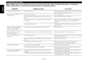
... Troubleshooting Guide What might seem to be a malfunction in the unit. Check the speaker wiring. No sound can be heard, or the volume is dirty. The battery wire has not been connected to the proper terminal. Turn off . The antenna control wire is not functioning normally. Before calling service, first check the following table for short circuits in the wires, replace the fuse with one side. The input/output wires or wiring harness are connected...
... Troubleshooting Guide What might seem to be a malfunction in the unit. Check the speaker wiring. No sound can be heard, or the volume is dirty. The battery wire has not been connected to the proper terminal. Turn off . The antenna control wire is not functioning normally. Before calling service, first check the following table for short circuits in the wires, replace the fuse with one side. The input/output wires or wiring harness are connected...
Instruction Manual
Page 17
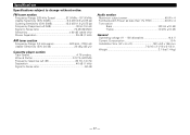
... Noise ratio 52 dB Audio section Maximum output power 40 W x 4 Full Bandwidth Power (at less than 1% THD 20 W x 4 Tone action Bass 100 Hz ±10 dB Treble 10 kHz ±10 dB General Operating voltage (11 - 16V allowable 14.4 V Current Consumption 10 A Installation Size (W x H x D 182 x 53 x 155 mm 7-3/16 x 2-1/16 x 6-1/8 in. Wow & Flutter 0.12 % (WRMS) Frequency response (±3 dB...
... Noise ratio 52 dB Audio section Maximum output power 40 W x 4 Full Bandwidth Power (at less than 1% THD 20 W x 4 Tone action Bass 100 Hz ±10 dB Treble 10 kHz ±10 dB General Operating voltage (11 - 16V allowable 14.4 V Current Consumption 10 A Installation Size (W x H x D 182 x 53 x 155 mm 7-3/16 x 2-1/16 x 6-1/8 in. Wow & Flutter 0.12 % (WRMS) Frequency response (±3 dB...


