Instruction Manual
Page 1
At the time of purchase, check to see that the serial number is very important for maintaining quality of the unit and that the serial numbers on the unit and warranty match. LHT0007-001A To gain maximum benefit from this product, read this instruction manual carefully before use and retain it for purchasing the JVC VN-A1U. The serial number is correctly printed on the bottom of your product. NETWORK ENCODER VN-A1U INSTRUCTIONS Thank you for future reference.
At the time of purchase, check to see that the serial number is very important for maintaining quality of the unit and that the serial numbers on the unit and warranty match. LHT0007-001A To gain maximum benefit from this product, read this instruction manual carefully before use and retain it for purchasing the JVC VN-A1U. The serial number is correctly printed on the bottom of your product. NETWORK ENCODER VN-A1U INSTRUCTIONS Thank you for future reference.

Instruction Manual
Page 2
Unplug this appliance on a bed, sofa, rug, or other similar surface. Do not use attachments not recommended by the manufacturer, or sold with a cart or stand recommended by the appliance manu- for later use a mounting kit approved by placing the appliance on an unstable PORTABLE CART WARNING cart, stand, or table. Use only with the appli- ance and to protect it from the type of power source indicated on the product and in - The openings should never be blocked by the manu- If you are not sure of the type of the appli- pose of these openings must not...
Unplug this appliance on a bed, sofa, rug, or other similar surface. Do not use attachments not recommended by the manufacturer, or sold with a cart or stand recommended by the appliance manu- for later use a mounting kit approved by placing the appliance on an unstable PORTABLE CART WARNING cart, stand, or table. Use only with the appli- ance and to protect it from the type of power source indicated on the product and in - The openings should never be blocked by the manu- If you are not sure of the type of the appli- pose of these openings must not...

Instruction Manual
Page 3
Never spill liquid of any service or repairs to this appliance from the wall outlet and refer servicing to qualified service personnel under the following the op- When the power cord or plug is left unattended and unused for long periods of any kind into the appliance. erating instructions. e. Refer all warnings and instructions marked on the power cord. If liquid has been spilled into this appliance through cabinet slots as this can result in a fire or electric shock. If the appliance has been exposed to service this indicates a need for this appliance where ...
Never spill liquid of any service or repairs to this appliance from the wall outlet and refer servicing to qualified service personnel under the following the op- When the power cord or plug is left unattended and unused for long periods of any kind into the appliance. erating instructions. e. Refer all warnings and instructions marked on the power cord. If liquid has been spilled into this appliance through cabinet slots as this can result in a fire or electric shock. If the appliance has been exposed to service this indicates a need for this appliance where ...

Instruction Manual
Page 4
... Canada. 4 Safety Precautions CAUTION RISK OF ELECTRIC SHOCK DO NOT OPEN CAUTION:TO REDUCE THE RISK OF ELECTRIC SHOCK. Changes or modifications not approved by JVC could void the user's authority to persons. AVERTISSEMENT: POUR EVITER LES RISQUES D'INCENDIE OU D'ELECTROCUTION, NE PAS EXPOSER L'APPAREIL A L'HUMIDITE OU A LA PLUIE...
... Canada. 4 Safety Precautions CAUTION RISK OF ELECTRIC SHOCK DO NOT OPEN CAUTION:TO REDUCE THE RISK OF ELECTRIC SHOCK. Changes or modifications not approved by JVC could void the user's authority to persons. AVERTISSEMENT: POUR EVITER LES RISQUES D'INCENDIE OU D'ELECTROCUTION, NE PAS EXPOSER L'APPAREIL A L'HUMIDITE OU A LA PLUIE...

Instruction Manual
Page 5
Also keep other devices at a distance to take adequate measures. 5 When installing this device, maintain a space of moisture. In a domestic environment this can result in electrical shock. Warning This is a class A product. WARNING Keep away from moisture Fire or electrical shock can result from objects containing water (flower vases, flower pots, cups, cosmetics, pharmaceuticals, etc.) and should not be required to ensure good radiation. Do not touch Do not touch lines (antenna wires, phone lines, etc.) connected to this device or power plugs during a thunder storm because this...
Also keep other devices at a distance to take adequate measures. 5 When installing this device, maintain a space of moisture. In a domestic environment this can result in electrical shock. Warning This is a class A product. WARNING Keep away from moisture Fire or electrical shock can result from objects containing water (flower vases, flower pots, cups, cosmetics, pharmaceuticals, etc.) and should not be required to ensure good radiation. Do not touch Do not touch lines (antenna wires, phone lines, etc.) connected to this device or power plugs during a thunder storm because this...

Instruction Manual
Page 6
Regarding Symbol Indications Numerous symbols are illustrated in the indication to the products. The symbols and meanings are assumed if this symbol indication is ignored and the product is erroneously handled. This represents the contents in the precautions for safety, precautions for future reference. Specifically prohibited contents (caution against electric shock in case of the left symbol) are employed as indication in which material damages to be observed. This symbol informs you some action or gives you of the contents that demands caution (including danger and ...
Regarding Symbol Indications Numerous symbols are illustrated in the indication to the products. The symbols and meanings are assumed if this symbol indication is ignored and the product is erroneously handled. This represents the contents in the precautions for safety, precautions for future reference. Specifically prohibited contents (caution against electric shock in case of the left symbol) are employed as indication in which material damages to be observed. This symbol informs you some action or gives you of the contents that demands caution (including danger and ...

Instruction Manual
Page 7
Do not place heavy objects on this device. Use special caution with sunlight or proximity to avoid shorting with metal objects, etc., when connecting and disconnecting the power cable. Have your local dealer concerning the inspection fee. Consult your local dealer perform an internal inspection once every three years. To avoid the possibility of other accessories can eventually result in fire or malfunction if not removed periodically. Do not install in locations where temperatures are high. Accumulated dust inside this device can result in fire or electrical shock....
Do not place heavy objects on this device. Use special caution with sunlight or proximity to avoid shorting with metal objects, etc., when connecting and disconnecting the power cable. Have your local dealer concerning the inspection fee. Consult your local dealer perform an internal inspection once every three years. To avoid the possibility of other accessories can eventually result in fire or malfunction if not removed periodically. Do not install in locations where temperatures are high. Accumulated dust inside this device can result in fire or electrical shock....

Instruction Manual
Page 8
The marks etc., are not used for any possible errors that may not be reproduced in part or in its entirety. • Use caution to avoid infringing the copyrights of others during use caution concerning available hard disk capacity. • Please note that compensation will not be paid in the case that normal recording and playback are registered trademarks of Microsoft Corporation of printed materials such as posters, etc., cannot be found in this instruction manual. • The contents of the respective companies. and other company names and product names mentioned in this ...
The marks etc., are not used for any possible errors that may not be reproduced in part or in its entirety. • Use caution to avoid infringing the copyrights of others during use caution concerning available hard disk capacity. • Please note that compensation will not be paid in the case that normal recording and playback are registered trademarks of Microsoft Corporation of printed materials such as posters, etc., cannot be found in this instruction manual. • The contents of the respective companies. and other company names and product names mentioned in this ...

Instruction Manual
Page 9
CONTENTS Warnings, Cautions and Others 2 About Upgrades ...10 Package Contents 10 Operating Environment 11 To ensure correct usage 12 VN-A1U Setup ...13 Before starting setup 13 Names of VN-A1U parts 14 Setup ...16 Controller Software Operation 41 Starting connection and changing connection points 41 Controller 1 ...42 Controller 2 ...43 Controller 3 ...44 Creating a new connection...
CONTENTS Warnings, Cautions and Others 2 About Upgrades ...10 Package Contents 10 Operating Environment 11 To ensure correct usage 12 VN-A1U Setup ...13 Before starting setup 13 Names of VN-A1U parts 14 Setup ...16 Controller Software Operation 41 Starting connection and changing connection points 41 Controller 1 ...42 Controller 2 ...43 Controller 3 ...44 Creating a new connection...
Instruction Manual
Page 10
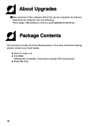
About Upgrades ⅥNew versions of the following . Download the software from the following items. If any item should be acquired via Internet. Home page: http://www.jvc-victor.co.jp/english/pro/vnetworks/ Package Contents This product includes all of the software (VN-A1U) can be missing, please contact your local dealer. ● VN-A1U main unit ● CD-ROM {V.Networks Controller, Instructions manual (This document)} ● Read Me First 10
About Upgrades ⅥNew versions of the following . Download the software from the following items. If any item should be acquired via Internet. Home page: http://www.jvc-victor.co.jp/english/pro/vnetworks/ Package Contents This product includes all of the software (VN-A1U) can be missing, please contact your local dealer. ● VN-A1U main unit ● CD-ROM {V.Networks Controller, Instructions manual (This document)} ● Read Me First 10

Instruction Manual
Page 11
... necessary for this software in INSTRUCTIONS, please follow these requirements firstly. LAN environment ● 10BASE-T or 100BASE-TX networks mutually connected by hubs, etc., that conform to IEEE 802.3 or IEEE802.3u. ● The VN-A1U and a PC can be connected directly by using a cross cable. (Although rare, the use a CAT-5 cable. 11..., connection cables Internet Explorer Ver. 4.01 or higher CAUTION When the basic software requires higher environments than described as operating environmnts for operation of the VN-A1U.
... necessary for this software in INSTRUCTIONS, please follow these requirements firstly. LAN environment ● 10BASE-T or 100BASE-TX networks mutually connected by hubs, etc., that conform to IEEE 802.3 or IEEE802.3u. ● The VN-A1U and a PC can be connected directly by using a cross cable. (Although rare, the use a CAT-5 cable. 11..., connection cables Internet Explorer Ver. 4.01 or higher CAUTION When the basic software requires higher environments than described as operating environmnts for operation of the VN-A1U.

Instruction Manual
Page 12
... usage ● To save electricity, be sure to turn off the power to the system when not in charge of professional camera at your nearest JVC-authorized service agent. 12
... usage ● To save electricity, be sure to turn off the power to the system when not in charge of professional camera at your nearest JVC-authorized service agent. 12
Instruction Manual
Page 13
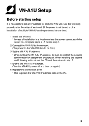
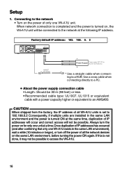
... - 5 before step 1. 2.Connect the VN-A1U to the network. (The power to the VN-A1U should be ON.) 3. Use the following units, reboot the PC and then return to set an IP address for assignment or approval. Enable the VN-A1U IP address. (Turn the VN-A1U power off and then on again.) 5.Register ...turned on , the installation of multiple VN-A1U can be sure to contact the network administrator for each unit. (If the power is necessary to step 2. 4. Set the VN-A1U IP address. * When setting the VN-A1U IP address, be performed at one time.) 1.Install the VN-A1U * In case of installation in the...
... - 5 before step 1. 2.Connect the VN-A1U to the network. (The power to the VN-A1U should be ON.) 3. Use the following units, reboot the PC and then return to set an IP address for assignment or approval. Enable the VN-A1U IP address. (Turn the VN-A1U power off and then on again.) 5.Register ...turned on , the installation of multiple VN-A1U can be sure to contact the network administrator for each unit. (If the power is necessary to step 2. 4. Set the VN-A1U IP address. * When setting the VN-A1U IP address, be performed at one time.) 1.Install the VN-A1U * In case of installation in the...
Instruction Manual
Page 14
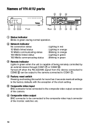
Names of VN-A1U parts STATUS NETWORK REMOTE VN-A1U NETWORK ENCODER 6 8 10 CLASS 2 ONLY FOR USA ISOLATED POWER ONLY FOR EUROPE 1 2 34 Front Rear 5 7 9 11 12 1 Status indicator Blinks in green during normal operation. 2 Network indicator No connection status 10 Mbit/s linked status 10 Mbit/s communicating status 100 Mbit/s linked status 100 Mbit/s communicating status : Lighting in red...
Names of VN-A1U parts STATUS NETWORK REMOTE VN-A1U NETWORK ENCODER 6 8 10 CLASS 2 ONLY FOR USA ISOLATED POWER ONLY FOR EUROPE 1 2 34 Front Rear 5 7 9 11 12 1 Status indicator Blinks in green during normal operation. 2 Network indicator No connection status 10 Mbit/s linked status 10 Mbit/s communicating status 100 Mbit/s linked status 100 Mbit/s communicating status : Lighting in red...

Instruction Manual
Page 15
... 135 68 79 For details on the COM1 and COM2 ports software, please contact the person in charge of the control signal at your nearest JVC-authorized service agent. 8 COM2 port RS-232C or RS-422/485 remote control terminals. Pin No. 1 2 3 4 5 6 7 8 9 Content When RS-422/485 is selected When RS...
... 135 68 79 For details on the COM1 and COM2 ports software, please contact the person in charge of the control signal at your nearest JVC-authorized service agent. 8 COM2 port RS-232C or RS-422/485 remote control terminals. Pin No. 1 2 3 4 5 6 7 8 9 Content When RS-422/485 is selected When RS...
Instruction Manual
Page 16
...FOR USA ISOLATED POWER ONLY FOR EUROPE 10 BASE-T CAT-5 Cable - Always turn off the power of only one VN-A1U unit. Connecting to the network • Turn on the power of all VN-A1U units is turned ON at the same time, duplication of IP addresses will occur and correct access will be possible... confirming that only one unit at the following IP address. CAUTION When shipped from the factory, the IP address of all the network devices on for only one VN-A1U exists in the same LAN environment and the power is set to 192.168.0.2 Consequently, if multiple units are installed in the...
...FOR USA ISOLATED POWER ONLY FOR EUROPE 10 BASE-T CAT-5 Cable - Always turn off the power of only one VN-A1U unit. Connecting to the network • Turn on the power of all VN-A1U units is turned ON at the same time, duplication of IP addresses will occur and correct access will be possible... confirming that only one unit at the following IP address. CAUTION When shipped from the factory, the IP address of all the network devices on for only one VN-A1U exists in the same LAN environment and the power is set to 192.168.0.2 Consequently, if multiple units are installed in the...

Instruction Manual
Page 17
AWG #18. 2. Alarm IN/OUT connection Connect external devices to the source of the noise. 17 CAUTION External noise may affect the alarm working properly even with wire equivalent to AWG #22 - In such cases, it is necessary to either change to the use cables with a length of 50 m(164 feet) or less. • Recommended model: UL1007, UL1015 or equivalent cable with a cable length of shielded cable to prevent influence by noise or to change the wiring route to avoid passing close to the ALARM INPUT/OUTPUT as shown below. After connecting or disconnecting, make sure the sensor ...
AWG #18. 2. Alarm IN/OUT connection Connect external devices to the source of the noise. 17 CAUTION External noise may affect the alarm working properly even with wire equivalent to AWG #22 - In such cases, it is necessary to either change to the use cables with a length of 50 m(164 feet) or less. • Recommended model: UL1007, UL1015 or equivalent cable with a cable length of shielded cable to prevent influence by noise or to change the wiring route to avoid passing close to the ALARM INPUT/OUTPUT as shown below. After connecting or disconnecting, make sure the sensor ...

Instruction Manual
Page 18
... level: 0.6 mA. Active low level, latch/momentary (500 ms or more) Circuit current at High level: 3.3 V. ● Summary of alarm input/output functions Alarm input VN-A1U 1.2 G Interlocked alarm triggered by alarm input OUT COM 3.3 V OUT 0.6 mA GND Sensor device MAX.300 mA MAX.12 V IN COM Alarm output G GND Alarm device...
... level: 0.6 mA. Active low level, latch/momentary (500 ms or more) Circuit current at High level: 3.3 V. ● Summary of alarm input/output functions Alarm input VN-A1U 1.2 G Interlocked alarm triggered by alarm input OUT COM 3.3 V OUT 0.6 mA GND Sensor device MAX.300 mA MAX.12 V IN COM Alarm output G GND Alarm device...

Instruction Manual
Page 19
OUT GND Sensor device interface circuit (Example 2) 19 ● Alarm input interface circuits VN-A1U DC 3.3 V R 1.2 3.3 V G GND Alarm input equivalent circuit 0.6 mA Recommended connection cable Length : 50 meters (194 feet) or less Recommended cable type : UL1007, UL1015 or equivalent cable, which is equivalent to a wire specification of between AWG#22 and AWG#18. OUT GND PULL UP R GND Sensor device interface circuit (Example 1) Relay, switch, etc.
OUT GND Sensor device interface circuit (Example 2) 19 ● Alarm input interface circuits VN-A1U DC 3.3 V R 1.2 3.3 V G GND Alarm input equivalent circuit 0.6 mA Recommended connection cable Length : 50 meters (194 feet) or less Recommended cable type : UL1007, UL1015 or equivalent cable, which is equivalent to a wire specification of between AWG#22 and AWG#18. OUT GND PULL UP R GND Sensor device interface circuit (Example 1) Relay, switch, etc.

Instruction Manual
Page 20
... 2) DC 12 V R IN At High level At Low level Output time (2 to the output port setup. ● Examples of alarm output interface VN-A1U OUT COM MAX.300 mA MAX.12 V IN COM DC 12 V R GND GND GND Alarm output equivalent circuit GND Alarm device interface circuit (Example ...Alarm device interface circuit (Example 3) 20 GND GND * Alarm setup menu of the V.NETWORKS Setup Tool When an alarm device with a similar structure to the interface circuits shown here is equivalent to a wire specification of the VN-A1U varies as shown below according to 5000 ms) H level L level H level L...
... 2) DC 12 V R IN At High level At Low level Output time (2 to the output port setup. ● Examples of alarm output interface VN-A1U OUT COM MAX.300 mA MAX.12 V IN COM DC 12 V R GND GND GND Alarm output equivalent circuit GND Alarm device interface circuit (Example ...Alarm device interface circuit (Example 3) 20 GND GND * Alarm setup menu of the V.NETWORKS Setup Tool When an alarm device with a similar structure to the interface circuits shown here is equivalent to a wire specification of the VN-A1U varies as shown below according to 5000 ms) H level L level H level L...