Instruction Manual
Page 1
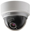
Retain this information for future reference. TK-C2201U,TK-C2201E Serial No. . LST0952-001A which is located on the body. Model No. FIXED DOME CAMERA TK-C2201U TK-C2201E INSTRUCTIONS For Customer Use: Enter below the Serial No.
Retain this information for future reference. TK-C2201U,TK-C2201E Serial No. . LST0952-001A which is located on the body. Model No. FIXED DOME CAMERA TK-C2201U TK-C2201E INSTRUCTIONS For Customer Use: Enter below the Serial No.
Instruction Manual
Page 2
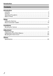
Introduction Contents Introduction Contents ...2 Features ...3 Operating Precautions 4 Name of Parts ...6 Setup Setting the Switches 9 About Connection Cables 10 Installation Mounting the Camera 12 Adjustment Adjusting Image 17 Adjusting the Auto White Balance 22 Mounting the Dome Cover 23 Others Specifications 25 2
Introduction Contents Introduction Contents ...2 Features ...3 Operating Precautions 4 Name of Parts ...6 Setup Setting the Switches 9 About Connection Cables 10 Installation Mounting the Camera 12 Adjustment Adjusting Image 17 Adjusting the Auto White Balance 22 Mounting the Dome Cover 23 Others Specifications 25 2
Instruction Manual
Page 3
... this "INSTRUCTIONS" and the information materials included to change for improvements without prior consent from the company. A : Indicates a reference page or item. Before use of other contents described in display mode (CRT or LCD selectable) How to this manual are trademarks or registered trademarks of this manual v JVC holds the copyright to read this product. R v Design, specifications and other...
... this "INSTRUCTIONS" and the information materials included to change for improvements without prior consent from the company. A : Indicates a reference page or item. Before use of other contents described in display mode (CRT or LCD selectable) How to this manual are trademarks or registered trademarks of this manual v JVC holds the copyright to read this product. R v Design, specifications and other...

Instruction Manual
Page 4
... not use for a long time, turn off the power for any damages. In a place subject to wipe the camera. Maintenance m v Clean the dome cover lens using (processing) it to compensate for safety and energy conservation reasons. m Energy Conservation v When the camera is cold air or near the air outlet of sudden temperature changes. Copyright Protection m v With the exception of the user...
... not use for a long time, turn off the power for any damages. In a place subject to wipe the camera. Maintenance m v Clean the dome cover lens using (processing) it to compensate for safety and energy conservation reasons. m Energy Conservation v When the camera is cold air or near the air outlet of sudden temperature changes. Copyright Protection m v With the exception of the user...
Instruction Manual
Page 5
Others m v When using the camera with [AGC] set to "MID" or "HIGH", the sensitivity increases automatically for dark images and the screen may appear grainy, but this camera is turned to "AUTO", the mode changes automatically to black and white in afterimage of a moving subject. v If the Easy DAY/NIGHT switch is moved from the actual color due to the principle of the automatic tracking...
Others m v When using the camera with [AGC] set to "MID" or "HIGH", the sensitivity increases automatically for dark images and the screen may appear grainy, but this camera is turned to "AUTO", the mode changes automatically to black and white in afterimage of a moving subject. v If the Easy DAY/NIGHT switch is moved from the actual color due to the principle of the automatic tracking...

Instruction Manual
Page 6
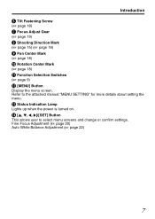
F ADJ M MENU N SET A Focus Adjustment Ring (A page 19) B Zoom Adjustment Ring (A page 19) C Fall Prevention Sheet (A page 13) D Rotation Knob (A page 18) E [MONITOR] Terminal (RCA pin) (A page 17) 6 .. Introduction Name of Parts Camera (Interior) The dome cover and inner dome are removed. A G B H C I D J K E L F. Refer to "Mounting the camera directly to the ceiling or on the wall" (A page 13) step 2 to 3 on the removal methods.
F ADJ M MENU N SET A Focus Adjustment Ring (A page 19) B Zoom Adjustment Ring (A page 19) C Fall Prevention Sheet (A page 13) D Rotation Knob (A page 18) E [MONITOR] Terminal (RCA pin) (A page 17) 6 .. Introduction Name of Parts Camera (Interior) The dome cover and inner dome are removed. A G B H C I D J K E L F. Refer to "Mounting the camera directly to the ceiling or on the wall" (A page 13) step 2 to 3 on the removal methods.
Instruction Manual
Page 7
...) Auto White Balance Adjustment (A page 22) 7 M Status Indication Lamp Lights up when the power is turned on. N [J, K, H, I Pan Center Mark (A page 18) J Rotation Center Mark (A page 18) K Function Selection Switches (A page 9) L [MENU] Button Display the menu screen. Refer to select menu screens and change or confirm settings. Introduction F Tilt Fastening Screw (A page 18) G Focus Adjust Gear (A page 19) H Shooting Direction Mark (A page 15) (A page 18) I ]/[SET] Button This allows user to the attached manual "MENU SETTING...
...) Auto White Balance Adjustment (A page 22) 7 M Status Indication Lamp Lights up when the power is turned on. N [J, K, H, I Pan Center Mark (A page 18) J Rotation Center Mark (A page 18) K Function Selection Switches (A page 9) L [MENU] Button Display the menu screen. Refer to select menu screens and change or confirm settings. Introduction F Tilt Fastening Screw (A page 18) G Focus Adjust Gear (A page 19) H Shooting Direction Mark (A page 15) (A page 18) I ]/[SET] Button This allows user to the attached manual "MENU SETTING...
Instruction Manual
Page 9
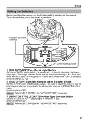
... image switches to color when the subject is bright, and black and white when it is adjusted according to the photometry area set to color at all times when "OFF" is selected. (Default setting: AUTO) 2 [BLC OFF/ON] Backlight Compensation Selector Switch Set this to see as brightness is dark. Setup Setting the Switches Before mounting the camera, set the switches, use . (Default setting: LCD) Memo Refer to "AUTO" when shooting a subject with continually changing...
... image switches to color when the subject is bright, and black and white when it is adjusted according to the photometry area set to color at all times when "OFF" is selected. (Default setting: AUTO) 2 [BLC OFF/ON] Backlight Compensation Selector Switch Set this to see as brightness is dark. Setup Setting the Switches Before mounting the camera, set the switches, use . (Default setting: LCD) Memo Refer to "AUTO" when shooting a subject with continually changing...
Instruction Manual
Page 10
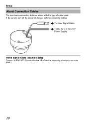
To video Signal Cable To DC 12 V or AC 24 V Power Supply Video signal cable (coaxial cable) Connect a RG-59 75 K coaxial cable (BNC) to turn off the power of cable used. Setup About Connection Cables The maximum connection distance varies with the type of devices before connecting cables. v Be sure to the video signal output connecter (BNC). 10 ..
To video Signal Cable To DC 12 V or AC 24 V Power Supply Video signal cable (coaxial cable) Connect a RG-59 75 K coaxial cable (BNC) to turn off the power of cable used. Setup About Connection Cables The maximum connection distance varies with the type of devices before connecting cables. v Be sure to the video signal output connecter (BNC). 10 ..
Instruction Manual
Page 11
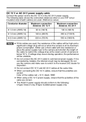
... send it is at the same time. v The AC24 V power supply should conform to below 10 %. The following : U-type: Class 2 only, E-type: Isolated power supply only 11 Color of the cables red: +12 V, black: GND v When using a DC 12 V power supply, ensure that the polarities are used, the resistance of camera to the following table shows the connection distances when 2-core VVF (vinylinsulated...
... send it is at the same time. v The AC24 V power supply should conform to below 10 %. The following : U-type: Class 2 only, E-type: Isolated power supply only 11 Color of the cables red: +12 V, black: GND v When using a DC 12 V power supply, ensure that the polarities are used, the resistance of camera to the following table shows the connection distances when 2-core VVF (vinylinsulated...
Instruction Manual
Page 12
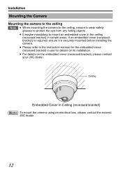
... to the instruction manual for the embedded cover (recessed bracket) in use for details on the embedded cover (recessed bracket), please contact your JVC dealer. Installation Mounting the Camera Mounting the camera to the ceiling Note v When mounting the camera to the ceiling, ensure to wear safety glasses to mount an embedded cover in the ceiling (recessed bracket) in Ceiling (recessed bracket) Memo To mount the camera using an...
... to the instruction manual for the embedded cover (recessed bracket) in use for details on the embedded cover (recessed bracket), please contact your JVC dealer. Installation Mounting the Camera Mounting the camera to the ceiling Note v When mounting the camera to the ceiling, ensure to wear safety glasses to mount an embedded cover in the ceiling (recessed bracket) in Ceiling (recessed bracket) Memo To mount the camera using an...
Instruction Manual
Page 13
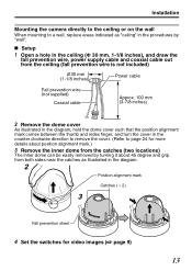
Installation Mounting the camera directly to the ceiling or on the wall When mounting to page 24 for video images (A page 9) 13 . .. m Setup 1 Open a hole in the ceiling (Φ 30 mm, 1-1/8 inches), and draw the fall prevention wire, power supply cable and coaxial cable out from both sides near the catches as illustrated in the procedures by turning it about 45 degree and grip from...
Installation Mounting the camera directly to the ceiling or on the wall When mounting to page 24 for video images (A page 9) 13 . .. m Setup 1 Open a hole in the ceiling (Φ 30 mm, 1-1/8 inches), and draw the fall prevention wire, power supply cable and coaxial cable out from both sides near the catches as illustrated in the procedures by turning it about 45 degree and grip from...

Instruction Manual
Page 14
... work conditions, as well as reduce penetration by noise and other objects. 1 Fall prevention wire 2 Protection cover Coaxial cable Power cable 3 Solder or caulk 4 Insulating tape .. 14 Upon connecting, restore the protection cover to the camera (fall prevention wire from the ceiling structures. 3 Connect the power supply cable (A page 11) 4 Wrap insulation tapes around the connecting parts of the connectors from the ceiling to cover the connectors. Installation Mounting...
... work conditions, as well as reduce penetration by noise and other objects. 1 Fall prevention wire 2 Protection cover Coaxial cable Power cable 3 Solder or caulk 4 Insulating tape .. 14 Upon connecting, restore the protection cover to the camera (fall prevention wire from the ceiling structures. 3 Connect the power supply cable (A page 11) 4 Wrap insulation tapes around the connecting parts of the connectors from the ceiling to cover the connectors. Installation Mounting...

Instruction Manual
Page 16
The basic mounting method is possible to the ceiling or wall Cable 16 Installation Mounting the Camera (Continued) Mount by allowing the cable to exit from the side When mounting the camera to the ceiling or a wall, it to guide the cable from the extraction hole and mount it is identical to steps in "Mounting the camera directly to the ceiling or on the wall" (A page 13) . 1 Cut both ends of the extraction hole for the cable with a nipper and break off the excess material using tools such as long-nose pliers 2 Pull out the cable from the side without opening any holes. .. . .
The basic mounting method is possible to the ceiling or wall Cable 16 Installation Mounting the Camera (Continued) Mount by allowing the cable to exit from the side When mounting the camera to the ceiling or a wall, it to guide the cable from the extraction hole and mount it is identical to steps in "Mounting the camera directly to the ceiling or on the wall" (A page 13) . 1 Cut both ends of the extraction hole for the cable with a nipper and break off the excess material using tools such as long-nose pliers 2 Pull out the cable from the side without opening any holes. .. . .

Instruction Manual
Page 17
Discharge the static electricity from your body by touching the metallic part of the monitor terminal before handling the camera as static electricity may cause the camera to malfunction. 1 Mount the monitor Connect the monitor terminal of this camera to a test monitor to adjust the camera's shooting direction, image and focus. 2 Turn on the camera Monitor terminal 75 terminal Monitor 17 .. Adjustment Adjusting Image After mounting the camera, adjust the images while looking at the actual image.
Discharge the static electricity from your body by touching the metallic part of the monitor terminal before handling the camera as static electricity may cause the camera to malfunction. 1 Mount the monitor Connect the monitor terminal of this camera to a test monitor to adjust the camera's shooting direction, image and focus. 2 Turn on the camera Monitor terminal 75 terminal Monitor 17 .. Adjustment Adjusting Image After mounting the camera, adjust the images while looking at the actual image.
Instruction Manual
Page 20
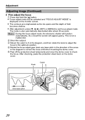
... position. ④ Rotate the focus adjust gear knob one base pitch in the direction of field becomes shallow. This is displayed on the dome cover. .. Memo During the focus adjust mode, the electronic shutter will appear grainy. As a result the screen will function automatically. Knob Catch A One base pitch 20 v After adjustment, press [K, H, I], [SET] or [MENU] to check the focus. After checking, paste the protection sheet...
... position. ④ Rotate the focus adjust gear knob one base pitch in the direction of field becomes shallow. This is displayed on the dome cover. .. Memo During the focus adjust mode, the electronic shutter will appear grainy. As a result the screen will function automatically. Knob Catch A One base pitch 20 v After adjustment, press [K, H, I], [SET] or [MENU] to check the focus. After checking, paste the protection sheet...
Instruction Manual
Page 22
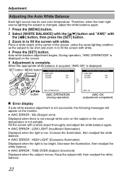
... MENU SET button AWC OPERATION AWC OPERATION (during operation) AWC OK AWC OK (adjustment completed) . Adjustment Adjusting the Auto White Balance Each light source has its own color temperature. Increase the illumination, then readjust the white balance. v AWC ERROR : TIME OVER (Subject movement) Displayed when the subject moves. Error display m If auto white balance adjustment is low. When the appropriate white balance is acquired, "AWC OK" is changed, adjust the white balance again. 1 Press the [MENU] button. 2 Select [WHITE...
... MENU SET button AWC OPERATION AWC OPERATION (during operation) AWC OK AWC OK (adjustment completed) . Adjustment Adjusting the Auto White Balance Each light source has its own color temperature. Increase the illumination, then readjust the white balance. v AWC ERROR : TIME OVER (Subject movement) Displayed when the subject moves. Error display m If auto white balance adjustment is low. When the appropriate white balance is acquired, "AWC OK" is changed, adjust the white balance again. 1 Press the [MENU] button. 2 Select [WHITE...

Instruction Manual
Page 24
...) 2 Mount the dome cover, and peel off the dome cover protection sheet ① Align the position marks of the same shape on the camera unit and dome cover. (Camera unit: double track, dome cover: double track) ② Turn and secure the dome cover in the clockwise dirction. If the field angle is removed again after mounting the dome cover, the field angle may changed , re-adjust the focus and...
...) 2 Mount the dome cover, and peel off the dome cover protection sheet ① Align the position marks of the same shape on the camera unit and dome cover. (Camera unit: double track, dome cover: double track) ② Turn and secure the dome cover in the clockwise dirction. If the field angle is removed again after mounting the dome cover, the field angle may changed , re-adjust the focus and...
Instruction Manual
Page 25
... 7 Angle adjustment : Pan: 175 57 range Tilt: 80 57 Rotation: 100 57 Power supply : AC 24 V 60 Hz, DC 12 V (TK-C2201U) AC 24 V 50 Hz/60 Hz, DC 12 V (TK-C2201E) Power/current consumption : 2.3 W (TK-C2201U) 190 mA (TK-C2201E) Mass : 330 g Ambient temperature : -10 f to 50 f (14 g to 122 g) (Operation) 0 f to 40 f (32 g to 104 g) (Recommended) Accessories : (TK-C2201U) WARRANTY CARD 1 2 INSTRUCTIONS 3 2 SCREW 2 2 (TK-C2201E) INSTRUCTIONS 5 2 SCREW...
... 7 Angle adjustment : Pan: 175 57 range Tilt: 80 57 Rotation: 100 57 Power supply : AC 24 V 60 Hz, DC 12 V (TK-C2201U) AC 24 V 50 Hz/60 Hz, DC 12 V (TK-C2201E) Power/current consumption : 2.3 W (TK-C2201U) 190 mA (TK-C2201E) Mass : 330 g Ambient temperature : -10 f to 50 f (14 g to 122 g) (Operation) 0 f to 40 f (32 g to 104 g) (Recommended) Accessories : (TK-C2201U) WARRANTY CARD 1 2 INSTRUCTIONS 3 2 SCREW 2 2 (TK-C2201E) INSTRUCTIONS 5 2 SCREW...
Instruction Manual
Page 28
2009 Victor Company of Japan, Limited Q LST0952-001A TK-C2201U/TK-C2201E FIXED DOME CAMERA
2009 Victor Company of Japan, Limited Q LST0952-001A TK-C2201U/TK-C2201E FIXED DOME CAMERA


