
Instructions
Page 2
...pro-vided for ventilation, and to insure reliable operation of power source indicated on the appliance. 13.Do not overload wall outlets and extension cords as this can result in fire or electric shock. 14.Never push objects of any service or repairs to this indicates a need for service. 17.When replacement parts...anything to . 4. Do not use a mounting kit approved by the appliance manufacturer as they may touch dangerous voltage points or short out parts that are not sure of the type of these instructions for cleaning. 5. Adjust only those controls that could result in a ...
...pro-vided for ventilation, and to insure reliable operation of power source indicated on the appliance. 13.Do not overload wall outlets and extension cords as this can result in fire or electric shock. 14.Never push objects of any service or repairs to this indicates a need for service. 17.When replacement parts...anything to . 4. Do not use a mounting kit approved by the appliance manufacturer as they may touch dangerous voltage points or short out parts that are not sure of the type of these instructions for cleaning. 5. Adjust only those controls that could result in a ...

Instructions
Page 4
...users) If you wish to dispose of this product, please visit our web page www.jvc-europe.com to obtain information about collection point and recycling of this product correctly, you will help to a secure location where it is in this manual...power supply only (For Europe). ⅷ This installation should conform to all local codes. ⅷ This installation shall be in accordance with applicable national legislation or other rules in your country for Burglar Alarm Functionality. ⅷ When mounting this unit to the ceiling or wall, mount it to conserve natural resources and will help...
...users) If you wish to dispose of this product, please visit our web page www.jvc-europe.com to obtain information about collection point and recycling of this product correctly, you will help to a secure location where it is in this manual...power supply only (For Europe). ⅷ This installation should conform to all local codes. ⅷ This installation shall be in accordance with applicable national legislation or other rules in your country for Burglar Alarm Functionality. ⅷ When mounting this unit to the ceiling or wall, mount it to conserve natural resources and will help...
Instructions
Page 5
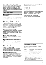
..., if activated, will not be installed outdoor directly as functions or constraints during alarm input. Ⅵ Easy DAY & NIGHT Feature This camera has an Easy Day & Night function. This is achieve by UL. How to Use This Manual Ⅵ Characters and symbols used in x3.6 varifocal lens (TK-C215VP4U/ E) and x12 zoom lens (TK-C215VP12U/E) enables detailed supervision. Ⅵ Alarm Zoom Feature (TK-C215VP12U/E only) 2 preset positions are available, which means the...
..., if activated, will not be installed outdoor directly as functions or constraints during alarm input. Ⅵ Easy DAY & NIGHT Feature This camera has an Easy Day & Night function. This is achieve by UL. How to Use This Manual Ⅵ Characters and symbols used in x3.6 varifocal lens (TK-C215VP4U/ E) and x12 zoom lens (TK-C215VP12U/E) enables detailed supervision. Ⅵ Alarm Zoom Feature (TK-C215VP12U/E only) 2 preset positions are available, which means the...
Instructions
Page 6
... video camera, VTR, hard disk recorder or video tape. ⅷ Before touching the camera unit, make sure to touch the metal surface of Alarm Input Terminals 18 The right sequence to connect and set the camera 19 Setting the switches 20 Mounting the base 21 Cable Connection 22 Mounting the camera unit 23 Adjusting the video image 25 Mounting the inner dome 30 Mounting the dome cover 30 Mounting the camera using the electrical box 31 Mounting the camera using the pipe ...... 32 White...
... video camera, VTR, hard disk recorder or video tape. ⅷ Before touching the camera unit, make sure to touch the metal surface of Alarm Input Terminals 18 The right sequence to connect and set the camera 19 Setting the switches 20 Mounting the base 21 Cable Connection 22 Mounting the camera unit 23 Adjusting the video image 25 Mounting the inner dome 30 Mounting the dome cover 30 Mounting the camera using the electrical box 31 Mounting the camera using the pipe ...... 32 White...
Instructions
Page 7
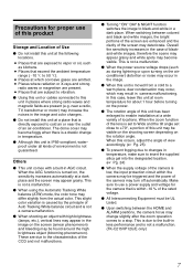
... not install this unit at the following locations. ● Places that are present (e.g. In this case, leave this unit may deteriorate. This slight color variation is not a malfunction. ⅷ When using the Automatic Tracking White balance (ATW) mode, the color tone may appear grainy. When switching between the HOME and ALARM positions, the camera focus may be visible on the shooting screen depending on the power...
... not install this unit at the following locations. ● Places that are present (e.g. In this case, leave this unit may deteriorate. This slight color variation is not a malfunction. ⅷ When using the Automatic Tracking White balance (ATW) mode, the color tone may appear grainy. When switching between the HOME and ALARM positions, the camera focus may be visible on the shooting screen depending on the power...

Instructions
Page 9
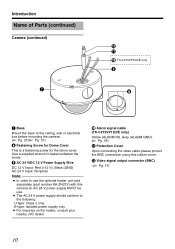
... wire to prevent this unit from falling accidentally. B Hole for Connecting Cable and Piping This is a hole for Fall Prevention Wire Use this screw when mounting the fall prevention wire to this unit. (Fall prevention wire is purchased or any nearby JVC dealer. D Dome Cover E Inner Dome Set the switches as well as angle of Parts Camera A B C F D E A Mounting hole ן2 Use these when mounting the camera to the ceiling, wall...
... wire to prevent this unit from falling accidentally. B Hole for Connecting Cable and Piping This is a hole for Fall Prevention Wire Use this screw when mounting the fall prevention wire to this unit. (Fall prevention wire is purchased or any nearby JVC dealer. D Dome Cover E Inner Dome Set the switches as well as angle of Parts Camera A B C F D E A Mounting hole ן2 Use these when mounting the camera to the ceiling, wall...
Instructions
Page 10
... 2 only E-type: Isolated power supply only ● For inquiries on the heater, consult your nearby JVC dealer. I H G Base Mount the base to fasten/unfasten the screw. J Alarm signal cable (TK-C215VP12U/E only) Yellow (ALARM IN), Gray (ALARM GND). (A Pg. 18) K Protection Cover Upon connecting the video cable please protect the BNC connection using this camera an AC 24 V power supply MUST be use the optional heater unit sold separately (part number KA-ZH215) with...
... 2 only E-type: Isolated power supply only ● For inquiries on the heater, consult your nearby JVC dealer. I H G Base Mount the base to fasten/unfasten the screw. J Alarm signal cable (TK-C215VP12U/E only) Yellow (ALARM IN), Gray (ALARM GND). (A Pg. 18) K Protection Cover Upon connecting the video cable please protect the BNC connection using this camera an AC 24 V power supply MUST be use the optional heater unit sold separately (part number KA-ZH215) with...

Instructions
Page 11
... a power connector for Heater Memo: ● When mounting the heater (sold separately: KA-ZH215), read the instruction manual of the heater carefully before mounting. P Camera Unit Fastening Screw ן2 Use this to connect the base G to the dome cover D. When removing the base, press toward the direction indicated by aligning the shooting direction with the arrow mark. Camera (Interior) M N O P Q R S T Lens (A next page) Y X W V U *TK-C215VP4U...
... a power connector for Heater Memo: ● When mounting the heater (sold separately: KA-ZH215), read the instruction manual of the heater carefully before mounting. P Camera Unit Fastening Screw ן2 Use this to connect the base G to the dome cover D. When removing the base, press toward the direction indicated by aligning the shooting direction with the arrow mark. Camera (Interior) M N O P Q R S T Lens (A next page) Y X W V U *TK-C215VP4U...
Instructions
Page 13
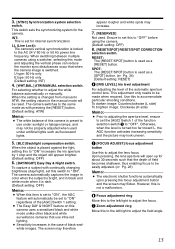
... [RESET] button. (Default setting: ATW) Memo: ● The white balance of field becomes shallower, thus enabling focus to adjust the field angle. 13 Use this camera uses a sensitized black and white mode unlike other black and white surveillance cameras that when the camera image is not a malfunction. When the object is locked to ATW, the setting values in the manual mode will appear brighter. (Default setting: OFF) 6. [DAY/NIGHT] Easy Day & Night switch. This adjustment only needs to...
... [RESET] button. (Default setting: ATW) Memo: ● The white balance of field becomes shallower, thus enabling focus to adjust the field angle. 13 Use this camera uses a sensitized black and white mode unlike other black and white surveillance cameras that when the camera image is not a malfunction. When the object is locked to ATW, the setting values in the manual mode will appear brighter. (Default setting: OFF) 6. [DAY/NIGHT] Easy Day & Night switch. This adjustment only needs to...
Instructions
Page 14
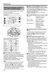
... set to SPOT: When this button is pressed, the value of home position is enabled Light on the status indication LED C will change accordingly. (A Pg. 28) E [RESET/SPOT] RESET/SPOT button When switch #8 is pressed when manually adjusting the white balance or when adjusting the vertical phase of the automatic aperture control lens. Otherwise, when the level is pressed, white-spots are factory position) 1 AGC 2 SELECT 3 SYNC 4 WHT.BAL. 5 BLC 6 DAY/NIGHT 7 ALARM 8 RESET...
... set to SPOT: When this button is pressed, the value of home position is enabled Light on the status indication LED C will change accordingly. (A Pg. 28) E [RESET/SPOT] RESET/SPOT button When switch #8 is pressed when manually adjusting the white balance or when adjusting the vertical phase of the automatic aperture control lens. Otherwise, when the level is pressed, white-spots are factory position) 1 AGC 2 SELECT 3 SYNC 4 WHT.BAL. 5 BLC 6 DAY/NIGHT 7 ALARM 8 RESET...
Instructions
Page 15
... The camera automatically captures the image in color when the subject is changed from manual to remain in black and white mode when it returns automatically to the home position. RESET: The [RESET/SPOT] button E is set for 15 seconds before it is dark. (Default setting: OFF) Note: ● When this mode and adjusting the vertical phase can reduce the monitor sync disturbances occur that you are used as [+/-] adjustment buttons. (Default setting...
... The camera automatically captures the image in color when the subject is changed from manual to remain in black and white mode when it returns automatically to the home position. RESET: The [RESET/SPOT] button E is set for 15 seconds before it is dark. (Default setting: OFF) Note: ● When this mode and adjusting the vertical phase can reduce the monitor sync disturbances occur that you are used as [+/-] adjustment buttons. (Default setting...
Instructions
Page 16
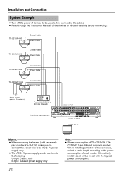
When installing a mixture of these models, select a cable length according to the following: U-type: Class 2 only E-type: Isolated power supply only Monitor Note: ● Power consumption of TK-C215VP4 / TKC215VP12 are different from one another. TK-C215VP4U/E Coaxial Cable Power Cable TK-C215VP4U/E Coaxial Cable Power Cable TK-C215VP4U/E Coaxial Cable Power Cable TK-C215VP12U/E Coaxial Cable Power Cable Alarm Signal (METAL CONTACT) Power Unit DC12 V or AC24 V (Class 2) VIDEO INPUT AUDIO IN Hard Disk Recorder, etc. 1 2 3 4 VIDEO IN THRU OUT SCSI RS-232C...
When installing a mixture of these models, select a cable length according to the following: U-type: Class 2 only E-type: Isolated power supply only Monitor Note: ● Power consumption of TK-C215VP4 / TKC215VP12 are different from one another. TK-C215VP4U/E Coaxial Cable Power Cable TK-C215VP4U/E Coaxial Cable Power Cable TK-C215VP4U/E Coaxial Cable Power Cable TK-C215VP12U/E Coaxial Cable Power Cable Alarm Signal (METAL CONTACT) Power Unit DC12 V or AC24 V (Class 2) VIDEO INPUT AUDIO IN Hard Disk Recorder, etc. 1 2 3 4 VIDEO IN THRU OUT SCSI RS-232C...

Instructions
Page 17
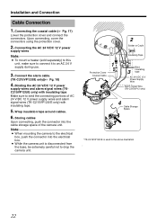
... the video signal output connector (BNC). with the type of devices before connecting cables. To video Signal Cable To DC 12 V or AC 24 V Power Supply To Alarm Signal Cable ( TK-C215VP12U/E Only) Note: ● When mounting the heater (sold separately part number KA-ZH215), make sure to connect the power wire to the camera. About Connection Cables The maximum connection distance varies with a high resistance), a significant voltage drop will occur when the unit...
... the video signal output connector (BNC). with the type of devices before connecting cables. To video Signal Cable To DC 12 V or AC 24 V Power Supply To Alarm Signal Cable ( TK-C215VP12U/E Only) Note: ● When mounting the heater (sold separately part number KA-ZH215), make sure to connect the power wire to the camera. About Connection Cables The maximum connection distance varies with a high resistance), a significant voltage drop will occur when the unit...

Instructions
Page 19
... setting the video image switches. Mounting the dome cover (A Pg. 30) Insert the silica gel into the designated space to prevent fogging of devices to connect/set the camera Follow the procedures below to be used before mounting. Mounting the base (A Pg. 21) Mount the base to the camera. Mounting the inner dome (A Pg. 30) After setting is complete, mount the inner dome to the wall or ceiling. Turn off the power of the dome...
... setting the video image switches. Mounting the dome cover (A Pg. 30) Insert the silica gel into the designated space to prevent fogging of devices to connect/set the camera Follow the procedures below to be used before mounting. Mounting the base (A Pg. 21) Mount the base to the camera. Mounting the inner dome (A Pg. 30) After setting is complete, mount the inner dome to the wall or ceiling. Turn off the power of the dome...
Instructions
Page 20
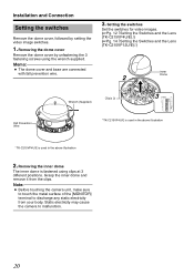
Memo: ● The dome cover and base are connected with fall prevention wire. 3. Note: ● Before touching the camera unit, make sure to touch the metal surface of the [MONITOR] terminal to malfunction. 20 Installation and Connection Setting the switches Remove the dome cover, followed by unfastening the 3 fastening screws using clips at 3 different positions. Removing the dome cover Remove the dome cover by setting the video image switches. 1. Static electricity...
Memo: ● The dome cover and base are connected with fall prevention wire. 3. Note: ● Before touching the camera unit, make sure to touch the metal surface of the [MONITOR] terminal to malfunction. 20 Installation and Connection Setting the switches Remove the dome cover, followed by unfastening the 3 fastening screws using clips at 3 different positions. Removing the dome cover Remove the dome cover by setting the video image switches. 1. Static electricity...
Instructions
Page 21
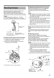
... the camera unit from the base and mount the base to the shooting direction. Mounting the base Mount the base by aligning the shooting direction mark on the camera unit to the base (fall prevention wire. 4. Use appropriate type of screw according to the material of the base (j) to the ceiling or wall. When mounting to a wall, follow the procedures by replacing areas indicated as [ceiling] by using the template supplied...
... the camera unit from the base and mount the base to the shooting direction. Mounting the base Mount the base by aligning the shooting direction mark on the camera unit to the base (fall prevention wire. 4. Use appropriate type of screw according to the material of the base (j) to the ceiling or wall. When mounting to a wall, follow the procedures by replacing areas indicated as [ceiling] by using the template supplied...
Instructions
Page 22
... camera unit. Connect the alarm cable. (TK-C215VP12U/E only)(A Pg. 18) 4. Storing cables Upon connecting, push the connector into the electrical box. ● While the camera unit is disconnected from the base, be extremely careful not to the electrical box, push the connector into the cable storage space of AC 24 V/DC 12 V power supply wires and alarm signal wires (TK-C215VP12U/E only) with insulating tape Make sure to an AC 24 V supply during use...
... camera unit. Connect the alarm cable. (TK-C215VP12U/E only)(A Pg. 18) 4. Storing cables Upon connecting, push the connector into the electrical box. ● While the camera unit is disconnected from the base, be extremely careful not to the electrical box, push the connector into the cable storage space of AC 24 V/DC 12 V power supply wires and alarm signal wires (TK-C215VP12U/E only) with insulating tape Make sure to an AC 24 V supply during use...

Instructions
Page 28
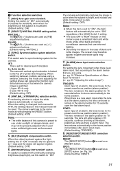
... electronic shutter mode is activated and the image may flicker. Adjust the angle of home position is an alarm input. (A Pg. 15) ⅷ Registering home position For registering the angle of view during monitoring under normal conditions. 4. 2.,3. 1. Note: ● When the [ZOOM / FOCUS] switch is set the actions when there is enabled. POSITION ZOOM/FOCUS SELECT FAR IRIS WIDE TELE NEAR L [MEMORY] LEVEL H Installation and Connection Adjusting the video image (continued) Ⅵ TK-C215VP12U/E ●...
... electronic shutter mode is activated and the image may flicker. Adjust the angle of home position is an alarm input. (A Pg. 15) ⅷ Registering home position For registering the angle of view during monitoring under normal conditions. 4. 2.,3. 1. Note: ● When the [ZOOM / FOCUS] switch is set the actions when there is enabled. POSITION ZOOM/FOCUS SELECT FAR IRIS WIDE TELE NEAR L [MEMORY] LEVEL H Installation and Connection Adjusting the video image (continued) Ⅵ TK-C215VP12U/E ●...

Instructions
Page 31
Memo: ● M4 screws are same as normal mounting ● Cable Connection (A Pg. 22) ● Mounting the camera unit to the electrical box. 1. Mounting the camera using the 2 mounting holes and 2 M4 screws. The following procedures are not supplied with this product. 4 Inch square electrical box Base M4 Screw 4. Setting the switches (A Pg. 20) 2. Otherwise, the humidity level may rise, which may cause the dust...
Memo: ● M4 screws are same as normal mounting ● Cable Connection (A Pg. 22) ● Mounting the camera unit to the electrical box. 1. Mounting the camera using the 2 mounting holes and 2 M4 screws. The following procedures are not supplied with this product. 4 Inch square electrical box Base M4 Screw 4. Setting the switches (A Pg. 20) 2. Otherwise, the humidity level may rise, which may cause the dust...

Instructions
Page 34
... SPOT CORRECTION button for completion. Installation and Connection White-spot correction As a general characteristic unique to CCDs, white-spots may appear on the camera power supply and wait for at least 30 minutes. Ⅵ TK-C215VP4U/E RESET/[SPOT] [SPOT] button B R LL PHASE 1 2 3 4 5 6 7 8 O N2 4 WHT. R B 6 7 8 LL PHASE RESET/[SPOT] [SPOT] button Function selection switch 8 1. Set the function selection switch 8 to [SPOT]. (A Pg. 13) 4. NEAR WIDE POSITION SELECT FAR POSITION ZOOM/FOCUS 5 4 4 3 2 2 ALARM 1 34...
... SPOT CORRECTION button for completion. Installation and Connection White-spot correction As a general characteristic unique to CCDs, white-spots may appear on the camera power supply and wait for at least 30 minutes. Ⅵ TK-C215VP4U/E RESET/[SPOT] [SPOT] button B R LL PHASE 1 2 3 4 5 6 7 8 O N2 4 WHT. R B 6 7 8 LL PHASE RESET/[SPOT] [SPOT] button Function selection switch 8 1. Set the function selection switch 8 to [SPOT]. (A Pg. 13) 4. NEAR WIDE POSITION SELECT FAR POSITION ZOOM/FOCUS 5 4 4 3 2 2 ALARM 1 34...


