Instructions
Page 2
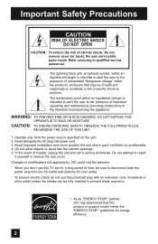
... receptacle or other outlet unless the blades can be fully inserted to prevent blade exposure. • As an "ENERGY STAR®" partner, JVC has determined that may be sure to the presence of important operating and maintenance (servicing) instructions in the literature accompanying the appliance. WARNING: ...Do not remove cover (or back). Do not attempt to qualified service personnel. Changes or modifications not approved by JVC could void the warranty. * When you don't use this TV set for a long period of time, be of sufficient magnitude to constitute a risk of electric shock to the...
... receptacle or other outlet unless the blades can be fully inserted to prevent blade exposure. • As an "ENERGY STAR®" partner, JVC has determined that may be sure to the presence of important operating and maintenance (servicing) instructions in the literature accompanying the appliance. WARNING: ...Do not remove cover (or back). Do not attempt to qualified service personnel. Changes or modifications not approved by JVC could void the warranty. * When you don't use this TV set for a long period of time, be of sufficient magnitude to constitute a risk of electric shock to the...
Instructions
Page 4
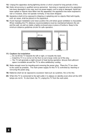
... operation. Keep to allow satisfactory cooling. 18) Make enough room for inserting and removing the power plug. Ensure that sufficient space is available around the TV to the minimum distance guidelines shown for safe operation. 200 mm 200 mm 150 mm 150 mm 50 mm POWER 17) Cautions for this... not operate normally, or has been dropped. 15) Apparatus shall not be placed on standby even when all servicing to qualified service personnel. Place the TV as close to dripping or splashing and no objects filled with liquids, such as sunshine, fire or the like. 20) When this...
... operation. Keep to allow satisfactory cooling. 18) Make enough room for inserting and removing the power plug. Ensure that sufficient space is available around the TV to the minimum distance guidelines shown for safe operation. 200 mm 200 mm 150 mm 150 mm 50 mm POWER 17) Cautions for this... not operate normally, or has been dropped. 15) Apparatus shall not be placed on standby even when all servicing to qualified service personnel. Place the TV as close to dripping or splashing and no objects filled with liquids, such as sunshine, fire or the like. 20) When this...
Instructions
Page 5
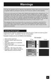
... this , mix your television's Channel Summary and they will all the channels your TV is detected and appears as available for scanning. Avoiding Ghost Images Displaying fixed images for their JVC TV remote control to scan or "surf". Even though every channel is receiving through the..., laser discs • Broadcast, cable, satellite channels or digital television tuners/converters For example... Examples include, but temporary ghost image on TV off XYZ XYZ 5 Once you run the Auto Tuner Setup (which detects and programs all be marked as available, you will only be...
... this , mix your television's Channel Summary and they will all the channels your TV is detected and appears as available for scanning. Avoiding Ghost Images Displaying fixed images for their JVC TV remote control to scan or "surf". Even though every channel is receiving through the..., laser discs • Broadcast, cable, satellite channels or digital television tuners/converters For example... Examples include, but temporary ghost image on TV off XYZ XYZ 5 Once you run the Auto Tuner Setup (which detects and programs all be marked as available, you will only be...
Instructions
Page 6
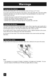
... with a soft cloth. This could cause scratches on the TV's surface. • DO NOT rub or scrub the TV harshly. The rear panel for models LT-37X688, LT-42X688, LT-37XM48 and LT-42XM48. If the screen is attached to enter the TV through the ventilation slots. • DO NOT use strong ...the TV. • DO NOT spray liquids or cleaners directly on the screen surface and image distortions. These will keep your connection cables tidy is very dirty, wipe it down the television, first unplug it gently with a soft cloth. Note: • This illustration is for models LT-42X788 and LT-...
... with a soft cloth. This could cause scratches on the TV's surface. • DO NOT rub or scrub the TV harshly. The rear panel for models LT-37X688, LT-42X688, LT-37XM48 and LT-42XM48. If the screen is attached to enter the TV through the ventilation slots. • DO NOT use strong ...the TV. • DO NOT spray liquids or cleaners directly on the screen surface and image distortions. These will keep your connection cables tidy is very dirty, wipe it down the television, first unplug it gently with a soft cloth. Note: • This illustration is for models LT-42X788 and LT-...

Instructions
Page 7
Warnings Disconnecting the stand If you disconnect the stand, attach the bottom cover and the screw (supplied) into the hole. Note: • To re-install the stand, reverse the procedure from the TV. 4) Cover the hole with a bottom cover and tighten the screw. This illustration is for models LT-42X788 and LT-47X788 using the same method. 1) Place the TV face down on a soft cloth on a table. 2) Remove the four screws from the back of the TV. 3) Pull out the stand from 4) to 1). 7 You can disconnect the stand for models LT-37X688, LT-42X688, LT-37XM48 and LT-42XM48.
Warnings Disconnecting the stand If you disconnect the stand, attach the bottom cover and the screw (supplied) into the hole. Note: • To re-install the stand, reverse the procedure from the TV. 4) Cover the hole with a bottom cover and tighten the screw. This illustration is for models LT-42X788 and LT-47X788 using the same method. 1) Place the TV face down on a soft cloth on a table. 2) Remove the four screws from the back of the TV. 3) Pull out the stand from 4) to 1). 7 You can disconnect the stand for models LT-37X688, LT-42X688, LT-37XM48 and LT-42XM48.

Instructions
Page 9
...a quick setup guide follows on the next few pages. 9 VOL + MUTING OK AVORITE DVR STATUS SOUND VIDEO ASPECT GUIDE SUB CH TV/VCR C.C. Before you begin setting up your new television, please check to make sure you for your purchase of the following items. ... - CH + - Cover x 1 Screw x 1 We recommend that before you can learn about your new television's many great features. Quick Setup Unpacking your TV Thank you have all of a JVC LCD Flat Television. BACK F Remote Control x 1 POWER MODE TV STB VCR DVD AUDIO INPUT V1 V2 V3 V4 V5 1 2 3 4 5 6 7 8 9 RETURN + TUNE...
...a quick setup guide follows on the next few pages. 9 VOL + MUTING OK AVORITE DVR STATUS SOUND VIDEO ASPECT GUIDE SUB CH TV/VCR C.C. Before you begin setting up your new television, please check to make sure you for your purchase of the following items. ... - CH + - Cover x 1 Screw x 1 We recommend that before you can learn about your new television's many great features. Quick Setup Unpacking your TV Thank you have all of a JVC LCD Flat Television. BACK F Remote Control x 1 POWER MODE TV STB VCR DVD AUDIO INPUT V1 V2 V3 V4 V5 1 2 3 4 5 6 7 8 9 RETURN + TUNE...

Instructions
Page 10
... Before you in understanding how to connect your television to another device, please refer to set up your specific TV and remote. Rear Panel Diagram AUDIO AUDIO AUDIO COMPONENT AUDIO COMPONENT AUDIO AUDIO AUDIO COMPONENT AUDIO COMPONENT INPUT 3 S-VIDEO Y VIDEO PB L PR R INPUT 4 INPUT 5 / INPUT 1 ...
... Before you in understanding how to connect your television to another device, please refer to set up your specific TV and remote. Rear Panel Diagram AUDIO AUDIO AUDIO COMPONENT AUDIO COMPONENT AUDIO AUDIO AUDIO COMPONENT AUDIO COMPONENT INPUT 3 S-VIDEO Y VIDEO PB L PR R INPUT 4 INPUT 5 / INPUT 1 ...
Instructions
Page 11
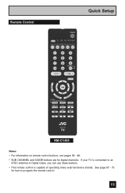
SUB T. CH + - DISPLAY SLEEP ML/MTS RM-C1450 TV RM-C1450 Notes: • For information on remote control buttons, see pages 58 - 66. • SUB CHANNEL and GUIDE buttons are for how to an ...; This remote control is capable of operating many external device brands. See page 67 - 72 for digital channels. Remote Control MENU Quick Setup POWER MODE TV STB VCR DVD AUDIO INPUT V1 V2 V3 V4 V5 1 2 3 4 5 6 7 8 9 RETURN + TUNE 0 TV - VOL + MUTING BACK F OK AVORITE DVR STATUS SOUND VIDEO ASPECT GUIDE SUB CH...
SUB T. CH + - DISPLAY SLEEP ML/MTS RM-C1450 TV RM-C1450 Notes: • For information on remote control buttons, see pages 58 - 66. • SUB CHANNEL and GUIDE buttons are for how to an ...; This remote control is capable of operating many external device brands. See page 67 - 72 for digital channels. Remote Control MENU Quick Setup POWER MODE TV STB VCR DVD AUDIO INPUT V1 V2 V3 V4 V5 1 2 3 4 5 6 7 8 9 RETURN + TUNE 0 TV - VOL + MUTING BACK F OK AVORITE DVR STATUS SOUND VIDEO ASPECT GUIDE SUB CH...

Instructions
Page 12
... the cover back into place. If this manual. If you have to be reset. See pages 67 - 72. Next, MENU select a menu using your TV, select the TV mode by pressing the POWER button at the top right corner of this is the first time you are used only for menu selections... the MENU button. Basic Operation Turn the television on and off by pressing the MODE button on the remote control before you turn the TV power on the TV, the interactive plug-in menu appears. • At first, to watch your new television right away. Quick Setup Getting Started These quick setup...
... the cover back into place. If this manual. If you have to be reset. See pages 67 - 72. Next, MENU select a menu using your TV, select the TV mode by pressing the POWER button at the top right corner of this is the first time you are used only for menu selections... the MENU button. Basic Operation Turn the television on and off by pressing the MODE button on the remote control before you turn the TV power on the TV, the interactive plug-in menu appears. • At first, to watch your new television right away. Quick Setup Getting Started These quick setup...
Instructions
Page 13
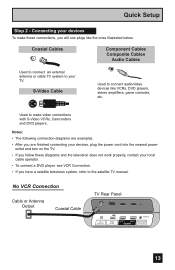
... Cables Component Cables Composite Cables Audio Cables Used to connect an external antenna or cable TV system to connect audio/video devices like the ones illustrated below. Used to the satellite TV manual. Notes: • The following connection diagrams are examples. • After you are finished ...connecting your devices, plug the power cord into the nearest power outlet and turn on the TV. • If you follow these connections, you have a satellite television system, refer to make these diagrams and the television does not work...
... Cables Component Cables Composite Cables Audio Cables Used to connect an external antenna or cable TV system to connect audio/video devices like the ones illustrated below. Used to the satellite TV manual. Notes: • The following connection diagrams are examples. • After you are finished ...connecting your devices, plug the power cord into the nearest power outlet and turn on the TV. • If you follow these connections, you have a satellite television system, refer to make these diagrams and the television does not work...
Instructions
Page 14
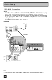
... PB L PR R INPUT 4 INPUT 5 / INPUT 1 AUDIO AUDIO OUT Y VIDEO VIDEO PB L L L PR R R R 75 Ω (VHF/UHF) PHOTO VIEWER INPUT 1 SERVICE INPUT 2 DIGITAL AUDIO OPTICAL OUT TV Rear Panel Green Blue Red Y PB PR OUT AUDIO OUT R L DVD Player Note: • If this connection setup does not work for DVD cables. Please...
... PB L PR R INPUT 4 INPUT 5 / INPUT 1 AUDIO AUDIO OUT Y VIDEO VIDEO PB L L L PR R R R 75 Ω (VHF/UHF) PHOTO VIEWER INPUT 1 SERVICE INPUT 2 DIGITAL AUDIO OPTICAL OUT TV Rear Panel Green Blue Red Y PB PR OUT AUDIO OUT R L DVD Player Note: • If this connection setup does not work for DVD cables. Please...

Instructions
Page 15
Diagram #2 R LV IN OUT VCR IN OUT OR Quick Setup Cable or Antenna Output IN Two-Way Splitter OUT OUT (Not supplied) Coaxial Cable AUDIO AUDIO AUDIO COMPONENT AUDIO COMPONENT INPUT 3 S-VIDEO Y VIDEO PB L PR R INPUT 4 INPUT 5 / INPUT 1 AUDIO AUDIO OUT Y VIDEO VIDEO PB L L L PR R R R Green Blue Red Y PB PR OUT AUDIO OUT R L DVD Player 75 Ω (VHF/UHF) PHOTO VIEWER INPUT 1 SERVICE INPUT 2 DIGITAL AUDIO OPTICAL OUT TV Rear Panel 15
Diagram #2 R LV IN OUT VCR IN OUT OR Quick Setup Cable or Antenna Output IN Two-Way Splitter OUT OUT (Not supplied) Coaxial Cable AUDIO AUDIO AUDIO COMPONENT AUDIO COMPONENT INPUT 3 S-VIDEO Y VIDEO PB L PR R INPUT 4 INPUT 5 / INPUT 1 AUDIO AUDIO OUT Y VIDEO VIDEO PB L L L PR R R R Green Blue Red Y PB PR OUT AUDIO OUT R L DVD Player 75 Ω (VHF/UHF) PHOTO VIEWER INPUT 1 SERVICE INPUT 2 DIGITAL AUDIO OPTICAL OUT TV Rear Panel 15
Instructions
Page 16
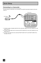
Quick Setup Connecting to a Camcorder You can connect a camcorder to the RIGHT AUDIO IN on the back of the TV. 16 TV Rear Panel CAMCORDER INPUT 3 S-VIDEO Y VIDEO PB L PR R INPUT 4 INPUT 5 / INPUT 1 AUDIO AUDIO OUT Y VIDEO VIDEO PB L L L PR R R R AUDIO AUDIO AUDIO COMPONENT AUDIO COMPONENT 1) Connect a ...yellow composite cable from the camcorder VIDEO OUT to the VIDEO IN on the back of the TV. 2) Connect a white cable from the camcorder LEFT AUDIO OUT to the LEFT AUDIO IN on the back of the...
Quick Setup Connecting to a Camcorder You can connect a camcorder to the RIGHT AUDIO IN on the back of the TV. 16 TV Rear Panel CAMCORDER INPUT 3 S-VIDEO Y VIDEO PB L PR R INPUT 4 INPUT 5 / INPUT 1 AUDIO AUDIO OUT Y VIDEO VIDEO PB L L L PR R R R AUDIO AUDIO AUDIO COMPONENT AUDIO COMPONENT 1) Connect a ...yellow composite cable from the camcorder VIDEO OUT to the VIDEO IN on the back of the TV. 2) Connect a white cable from the camcorder LEFT AUDIO OUT to the LEFT AUDIO IN on the back of the...
Instructions
Page 17
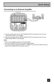
... will not be able to hear any audio from the RIGHT AUDIO OUTPUT on the back of the TV to the RIGHT AUDIO INPUT on the back of the TV to an External Amplifier TV Rear Panel Speaker Amplifier Speaker INPUT 3 S-VIDEO Y VIDEO PB L PR R INPUT 4 INPUT 5 / INPUT 1 AUDIO AUDIO OUT Y ...VIDEO VIDEO PB L L L PR R R R AUDIO AUDIO AUDIO COMPONENT AUDIO COMPONENT 1) Connect a white cable from the LEFT AUDIO OUTPUT on the back of the TV. 17 Quick Setup Connecting to the LEFT AUDIO INPUT on the amplifier. 2) Connect a red cable from the AUDIO OUT on the amplifier.
... will not be able to hear any audio from the RIGHT AUDIO OUTPUT on the back of the TV to the RIGHT AUDIO INPUT on the back of the TV to an External Amplifier TV Rear Panel Speaker Amplifier Speaker INPUT 3 S-VIDEO Y VIDEO PB L PR R INPUT 4 INPUT 5 / INPUT 1 AUDIO AUDIO OUT Y ...VIDEO VIDEO PB L L L PR R R R AUDIO AUDIO AUDIO COMPONENT AUDIO COMPONENT 1) Connect a white cable from the LEFT AUDIO OUTPUT on the back of the TV. 17 Quick Setup Connecting to the LEFT AUDIO INPUT on the amplifier. 2) Connect a red cable from the AUDIO OUT on the amplifier.
Instructions
Page 18
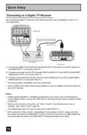
...and that if you do the above connection, set "Video-1 Audio" in their digital form. Quick Setup Connecting to a Digital TV Receiver By connecting a Digital TV Receiver, high definition pictures can only be used with the HDMI INPUT-1. • When setting the "Video-1 Audio - HDMI ... COMPONENT AUDIO COMPONENT INPUT 3 S-VIDEO Y VIDEO PB L PR R INPUT 4 INPUT 5 / INPUT 1 AUDIO AUDIO OUT Y VIDEO VIDEO PB L L L PR R R R TV Rear Panel After the connections have been made to the HDMI INPUT-1 along with a DTV decoder. See "Video-1 Audio", page 45. • The Analog Audio...
...and that if you do the above connection, set "Video-1 Audio" in their digital form. Quick Setup Connecting to a Digital TV Receiver By connecting a Digital TV Receiver, high definition pictures can only be used with the HDMI INPUT-1. • When setting the "Video-1 Audio - HDMI ... COMPONENT AUDIO COMPONENT INPUT 3 S-VIDEO Y VIDEO PB L PR R INPUT 4 INPUT 5 / INPUT 1 AUDIO AUDIO OUT Y VIDEO VIDEO PB L L L PR R R R TV Rear Panel After the connections have been made to the HDMI INPUT-1 along with a DTV decoder. See "Video-1 Audio", page 45. • The Analog Audio...
Instructions
Page 19
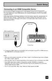
... Device LR AUDIO OUT DIGITAL OUT 75 Ω (VHF/UHF) PHOTO VIEWER INPUT 1 SERVICE INPUT 2 DIGITAL AUDIO OPTICAL OUT TV Rear Panel 1) Connect the HDMI Cable from the DIGITAL OUT on the back of your TV in the External Input menu to the HDMI INPUT-1 on the back of the... connected to the HDMI. • If the HDMI output device signal is changed (for a short time until the signal becomes stable. • This TV can be some distortion for example, 480i/60Hz is the first industry supported, uncompressed, all digital audio/video interface. HDMI (High Definition Multimedia Interface) is...
... Device LR AUDIO OUT DIGITAL OUT 75 Ω (VHF/UHF) PHOTO VIEWER INPUT 1 SERVICE INPUT 2 DIGITAL AUDIO OPTICAL OUT TV Rear Panel 1) Connect the HDMI Cable from the DIGITAL OUT on the back of your TV in the External Input menu to the HDMI INPUT-1 on the back of the... connected to the HDMI. • If the HDMI output device signal is changed (for a short time until the signal becomes stable. • This TV can be some distortion for example, 480i/60Hz is the first industry supported, uncompressed, all digital audio/video interface. HDMI (High Definition Multimedia Interface) is...
Instructions
Page 20
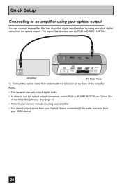
... the audio source is output can be PCM or DOLBY DIGITAL. 75 Ω (VHF/UHF) PHOTO VIEWER INPUT 1 SERVICE INPUT 2 DIGITAL AUDIO OPTICAL OUT Amplifier TV Rear Panel 1) Connect the optical cable from underneath the television to the back of the amplifier. Quick Setup Connecting to an amplifier using your optical...
... the audio source is output can be PCM or DOLBY DIGITAL. 75 Ω (VHF/UHF) PHOTO VIEWER INPUT 1 SERVICE INPUT 2 DIGITAL AUDIO OPTICAL OUT Amplifier TV Rear Panel 1) Connect the optical cable from underneath the television to the back of the amplifier. Quick Setup Connecting to an amplifier using your optical...

Instructions
Page 21
... television's V3 Smart Input By connecting your AV Receiver to your television's V3 Smart Input, you are using V3 Input as the V3 Smart Input. TV Rear Panel AV Receiver MONITOR OUT Y PB PR MONITOR OUT INPUT 3 S-VIDEO Y VIDEO INPUT 4 Y VIDEO VIDEO PB L PB L L L PR R PR R R R AUDIO ...AUDIO COMPONENT AUDIO COMPONENT 1) Connect an S-Video Cable from the AV Receiver's PR MONITOR OUT, into the PR VIDEO INPUT-3 on the back of the TV. 5) Connect a Red Component Cable from the AV Receiver's MONITOR OUT, to change or use the other devices like a DVD player. • Use...
... television's V3 Smart Input By connecting your AV Receiver to your television's V3 Smart Input, you are using V3 Input as the V3 Smart Input. TV Rear Panel AV Receiver MONITOR OUT Y PB PR MONITOR OUT INPUT 3 S-VIDEO Y VIDEO INPUT 4 Y VIDEO VIDEO PB L PB L L L PR R PR R R R AUDIO ...AUDIO COMPONENT AUDIO COMPONENT 1) Connect an S-Video Cable from the AV Receiver's PR MONITOR OUT, into the PR VIDEO INPUT-3 on the back of the TV. 5) Connect a Red Component Cable from the AV Receiver's MONITOR OUT, to change or use the other devices like a DVD player. • Use...
Instructions
Page 22
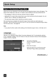
...in menu, it will skip over it. The plug-in menu helps you to get your TV ready to use by letting you set your TV, you want the onscreen menus to appear. • Setting the TV's clock to the "Set Clock" Plug-in Menu automatically. (Continued...) 22 After the ...; The language in which channels you complete the interactive plug-in three languages: English, French or Spanish. Language After the "JVC Interactive Plug-in Menu" has been displayed, the TV automatically switches to view your onscreen menus in items before you will move to the correct time so your television. We...
...in menu, it will skip over it. The plug-in menu helps you to get your TV ready to use by letting you set your TV, you want the onscreen menus to appear. • Setting the TV's clock to the "Set Clock" Plug-in Menu automatically. (Continued...) 22 After the ...; The language in which channels you complete the interactive plug-in three languages: English, French or Spanish. Language After the "JVC Interactive Plug-in Menu" has been displayed, the TV automatically switches to view your onscreen menus in items before you will move to the correct time so your television. We...
Instructions
Page 23
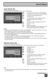
... Off" † To "set" Press the OK button Once you press OK, you will move to "Auto", the Daylight Saving Time feature automatically adjusts your TV's clock for the first time, you are using the time data sent via broadcasting. Note: • You will have to "On" in Menu automatically. However...
... Off" † To "set" Press the OK button Once you press OK, you will move to "Auto", the Daylight Saving Time feature automatically adjusts your TV's clock for the first time, you are using the time data sent via broadcasting. Note: • You will have to "On" in Menu automatically. However...


