
Instructions
Page 2
...receptacle or other outlet unless the blades can be fully inserted to prevent blade exposure. • As an "ENERGY STAR®" partner, JVC has determined that may be sure to constitute a risk of important operating and maintenance (servicing) instructions in the literature accompanying the appliance. ...product model meets the "ENERGY STAR®" guidelines for energy efficiency. 2 Changes or modifications not approved by JVC could void the warranty. * When you don't use this TV set for your safety. * To prevent electric shock do not use this polarized plug with arrowhead symbol, ...
...receptacle or other outlet unless the blades can be fully inserted to prevent blade exposure. • As an "ENERGY STAR®" partner, JVC has determined that may be sure to constitute a risk of important operating and maintenance (servicing) instructions in the literature accompanying the appliance. ...product model meets the "ENERGY STAR®" guidelines for energy efficiency. 2 Changes or modifications not approved by JVC could void the warranty. * When you don't use this TV set for your safety. * To prevent electric shock do not use this polarized plug with arrowhead symbol, ...

Instructions
Page 4
... unit where good ventilation is impossible. Keep to excessive heat such as sunshine, fire or the like. 20) When this apparatus during operation. Install the TV in any way, such as power-supply cord or plug is damaged, liquid has been spilled or objects have fallen into the apparatus, the apparatus...) Cautions for installation - Ensure that sufficient space is always on the floor so as inside a tightly enclosed area or piece of the way. - Place the TV as close to the outlet as vases, shall be maintained between the set and the wall, as well as to keep cords out of furniture...
... unit where good ventilation is impossible. Keep to excessive heat such as sunshine, fire or the like. 20) When this apparatus during operation. Install the TV in any way, such as power-supply cord or plug is damaged, liquid has been spilled or objects have fallen into the apparatus, the apparatus...) Cautions for installation - Ensure that sufficient space is always on the floor so as inside a tightly enclosed area or piece of the way. - Place the TV as close to the outlet as vases, shall be maintained between the set and the wall, as well as to keep cords out of furniture...

Instructions
Page 5
... channel number available from your viewing pattern. Even though every channel is important to note that you will all the channels your TV is not a malfunction of your cable company for extended periods of time can contact your television. Avoiding Ghost Images Displaying fi...;xed images for their JVC TV remote control to select channels. Warnings We have an important note for customers who subscribe to basic cable services (do not have ...
... channel number available from your viewing pattern. Even though every channel is important to note that you will all the channels your TV is not a malfunction of your cable company for extended periods of time can contact your television. Avoiding Ghost Images Displaying fi...;xed images for their JVC TV remote control to select channels. Warnings We have an important note for customers who subscribe to basic cable services (do not have ...
Instructions
Page 6
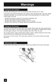
... the ventilation slots. • DO NOT use strong or abrasive cleaners on the TV. • DO NOT spray liquids or cleaners directly on the screen surface and image distortions. These will keep your connection cables tidy is attached to ..., organic solvents (like acetone), acidic or alkaline cleansers to help remove spots of the stand. 6 This could cause scratches on the TV's surface. • DO NOT rub or scrub the TV harshly. Warnings Caring for the Screen The screen is treated with a soft, non-scratching duster will remove the coating layer and...
... the ventilation slots. • DO NOT use strong or abrasive cleaners on the TV. • DO NOT spray liquids or cleaners directly on the screen surface and image distortions. These will keep your connection cables tidy is attached to ..., organic solvents (like acetone), acidic or alkaline cleansers to help remove spots of the stand. 6 This could cause scratches on the TV's surface. • DO NOT rub or scrub the TV harshly. Warnings Caring for the Screen The screen is treated with a soft, non-scratching duster will remove the coating layer and...

Instructions
Page 7
Note: • To re-install the stand, reverse the procedure from the TV. 4) Cover the hole with a bottom cover and tighten the screw. Warnings Disconnecting the stand If you disconnect the stand, attach the bottom cover and the screw (supplied) into the hole. 1) Place the TV face down on a soft cloth on a table. 2) Remove the four screws from the back of the TV. 3) Pull out the stand from 4) to 1). 7
Note: • To re-install the stand, reverse the procedure from the TV. 4) Cover the hole with a bottom cover and tighten the screw. Warnings Disconnecting the stand If you disconnect the stand, attach the bottom cover and the screw (supplied) into the hole. 1) Place the TV face down on a soft cloth on a table. 2) Remove the four screws from the back of the TV. 3) Pull out the stand from 4) to 1). 7

Instructions
Page 9
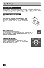
... 9 ASPECT MENU BACK GUIDE OK RM-C1291 TV + AA Alkaline - + AA Alkaline - Before you begin setting up your new television, please check to make sure you have all of a JVC LCD Flat Television. Quick Setup Unpacking your TV Thank you for your television box should include:... 1 Television POWER 1 Remote Control POWER SLEEP SUB CH V.STATUS SOUND 1 2 3 4 5 6 7 8 9 TUNE RETURN+/TV 0 V1 V2 V3 V4 MUTING CH+ V5 VO-...
... 9 ASPECT MENU BACK GUIDE OK RM-C1291 TV + AA Alkaline - + AA Alkaline - Before you begin setting up your new television, please check to make sure you have all of a JVC LCD Flat Television. Quick Setup Unpacking your TV Thank you for your television box should include:... 1 Television POWER 1 Remote Control POWER SLEEP SUB CH V.STATUS SOUND 1 2 3 4 5 6 7 8 9 TUNE RETURN+/TV 0 V1 V2 V3 V4 MUTING CH+ V5 VO-...

Instructions
Page 10
... INPUT 1 OPTICAL OUT INPUT 2 PHOTO VIEWER / SERVICE 75 Ω (VHF/UHF) DIGITAL AUDIO INPUT 1 OPTICAL OUT INPUT 2 PHOTO VIEWER / SERVICE INPUT MENU + CHANNEL - Quick Setup TV Models Before you in understanding how to connect your television to another device, please refer to set up your specific... TV and remote. These will help assist you connect your television to another device, as well as use the remote to the proper diagrams for your ...
... INPUT 1 OPTICAL OUT INPUT 2 PHOTO VIEWER / SERVICE 75 Ω (VHF/UHF) DIGITAL AUDIO INPUT 1 OPTICAL OUT INPUT 2 PHOTO VIEWER / SERVICE INPUT MENU + CHANNEL - Quick Setup TV Models Before you in understanding how to connect your television to another device, please refer to set up your specific... TV and remote. These will help assist you connect your television to another device, as well as use the remote to the proper diagrams for your ...

Instructions
Page 11
Remote Control Quick Setup POWER SLEEP SUB CH V.STATUS SOUND 1 2 3 4 5 6 7 8 9 TUNE RETURN+/TV 0 V1 V2 V3 V4 MUTING CH+ V5 VO- VOL + CH- ML/MTS DISPLAY C.C. ASPECT MENU BACK GUIDE OK RM-C1291 TV RM-C1291 Notes: • For information on remote control buttons, see pages 57 - 64. 11 L FAV.
Remote Control Quick Setup POWER SLEEP SUB CH V.STATUS SOUND 1 2 3 4 5 6 7 8 9 TUNE RETURN+/TV 0 V1 V2 V3 V4 MUTING CH+ V5 VO- VOL + CH- ML/MTS DISPLAY C.C. ASPECT MENU BACK GUIDE OK RM-C1291 TV RM-C1291 Notes: • For information on remote control buttons, see pages 57 - 64. 11 L FAV.
Instructions
Page 12
... other sections of the remote. Basic Operation Turn the television on the remote's back cover to remove. The four arrow keys are turning on the TV, the interactive plug-in the remote first. MENU BACK OK 12 Quick Setup Getting Started These quick setup pages will provide you, in three easy...
... other sections of the remote. Basic Operation Turn the television on the remote's back cover to remove. The four arrow keys are turning on the TV, the interactive plug-in the remote first. MENU BACK OK 12 Quick Setup Getting Started These quick setup pages will provide you, in three easy...

Instructions
Page 13
...the television does not work properly, contact your devices, plug the power cord into the nearest power outlet and turn on the TV. • If you follow these connections, you have a satellite television system, refer to connect audio/video devices like the ones illustrated... below. Connecting your TV. No VCR Connection Cable or Antenna Output Coaxial Cable TV Rear Panel 75 Ω (VHF/UHF) DIGITAL AUDIO INPUT 1 OPTICAL OUT INPUT 2 PHOTO VIEWER / SERVICE 13 Quick...
...the television does not work properly, contact your devices, plug the power cord into the nearest power outlet and turn on the TV. • If you follow these connections, you have a satellite television system, refer to connect audio/video devices like the ones illustrated... below. Connecting your TV. No VCR Connection Cable or Antenna Output Coaxial Cable TV Rear Panel 75 Ω (VHF/UHF) DIGITAL AUDIO INPUT 1 OPTICAL OUT INPUT 2 PHOTO VIEWER / SERVICE 13 Quick...

Instructions
Page 14
... AUDIO AUDIO AUDIO COMPONENT AUDIO COMPONENT INPUT 3 S-VIDEO Y VIDEO PB L PR R INPUT 4 Y VIDEO INPUT 5 / INPUT 1 AUDIO AUDIO OUT VIDEO PB L L L PR R R R 75 Ω (VHF/UHF) TV Rear Panel DIGITAL AUDIO INPUT 1 OPTICAL OUT INPUT 2 PHOTO VIEWER / SERVICE Green Blue Red Y PB PR OUT AUDIO OUT R L DVD Player Note: • If this...
... AUDIO AUDIO AUDIO COMPONENT AUDIO COMPONENT INPUT 3 S-VIDEO Y VIDEO PB L PR R INPUT 4 Y VIDEO INPUT 5 / INPUT 1 AUDIO AUDIO OUT VIDEO PB L L L PR R R R 75 Ω (VHF/UHF) TV Rear Panel DIGITAL AUDIO INPUT 1 OPTICAL OUT INPUT 2 PHOTO VIEWER / SERVICE Green Blue Red Y PB PR OUT AUDIO OUT R L DVD Player Note: • If this...

Instructions
Page 15
Diagram #2 R LV IN OUT VCR IN OUT OR Quick Setup Cable or Antenna Output IN Two-Way Splitter OUT OUT (Not supplied) Coaxial Cable AUDIO AUDIO AUDIO COMPONENT AUDIO COMPONENT INPUT 3 S-VIDEO Y VIDEO PB L PR R INPUT 4 INPUT 5 / INPUT 1 AUDIO AUDIO OUT Y VIDEO VIDEO PB L L L PR R R R 75 Ω (VHF/UHF) TV Rear Panel DIGITAL AUDIO INPUT 1 OPTICAL OUT INPUT 2 PHOTO VIEWER / SERVICE Green Blue Red Y PB PR OUT AUDIO OUT R L DVD Player 15
Diagram #2 R LV IN OUT VCR IN OUT OR Quick Setup Cable or Antenna Output IN Two-Way Splitter OUT OUT (Not supplied) Coaxial Cable AUDIO AUDIO AUDIO COMPONENT AUDIO COMPONENT INPUT 3 S-VIDEO Y VIDEO PB L PR R INPUT 4 INPUT 5 / INPUT 1 AUDIO AUDIO OUT Y VIDEO VIDEO PB L L L PR R R R 75 Ω (VHF/UHF) TV Rear Panel DIGITAL AUDIO INPUT 1 OPTICAL OUT INPUT 2 PHOTO VIEWER / SERVICE Green Blue Red Y PB PR OUT AUDIO OUT R L DVD Player 15

Instructions
Page 16
... will have only one AUDIO OUT. Quick Setup Connecting to a Camcorder You can connect a camcorder to the LEFT AUDIO IN on the back of the TV. 16 TV Rear Panel CAMCORDER INPUT 3 S-VIDEO Y VIDEO PB L PR R INPUT 4 INPUT 5 / INPUT 1 AUDIO AUDIO OUT Y VIDEO VIDEO PB L L L PR R R R AUDIO AUDIO AUDIO COMPONENT... AUDIO COMPONENT 1) Connect a yellow composite cable from the camcorder VIDEO OUT, into the VIDEO IN on the back of the TV. 2) Connect a white cable from the camcorder LEFT AUDIO OUT, into the LEFT AUDIO IN on the back of the...
... will have only one AUDIO OUT. Quick Setup Connecting to a Camcorder You can connect a camcorder to the LEFT AUDIO IN on the back of the TV. 16 TV Rear Panel CAMCORDER INPUT 3 S-VIDEO Y VIDEO PB L PR R INPUT 4 INPUT 5 / INPUT 1 AUDIO AUDIO OUT Y VIDEO VIDEO PB L L L PR R R R AUDIO AUDIO AUDIO COMPONENT... AUDIO COMPONENT 1) Connect a yellow composite cable from the camcorder VIDEO OUT, into the VIDEO IN on the back of the TV. 2) Connect a white cable from the camcorder LEFT AUDIO OUT, into the LEFT AUDIO IN on the back of the...

Instructions
Page 17
... a device connected to INPUT-1 or INPUT-2, you will not be able to the RIGHT AUDIO INPUT on the back of the TV. 17 Quick Setup Connecting to an External Amplifier TV Rear Panel Speaker Amplifier Speaker INPUT 3 S-VIDEO Y VIDEO PB L PR R INPUT 4 Y VIDEO INPUT 5 / INPUT 1 AUDIO AUDIO OUT VIDEO PB L L L PR R ...R R AUDIO AUDIO AUDIO COMPONENT AUDIO COMPONENT 1) Connect a white cable from the LEFT AUDIO OUTPUT on the back of the TV to the LEFT AUDIO INPUT on the amplifier. 2) Connect a red cable from the AUDIO OUT on the back of the...
... a device connected to INPUT-1 or INPUT-2, you will not be able to the RIGHT AUDIO INPUT on the back of the TV. 17 Quick Setup Connecting to an External Amplifier TV Rear Panel Speaker Amplifier Speaker INPUT 3 S-VIDEO Y VIDEO PB L PR R INPUT 4 Y VIDEO INPUT 5 / INPUT 1 AUDIO AUDIO OUT VIDEO PB L L L PR R ...R R AUDIO AUDIO AUDIO COMPONENT AUDIO COMPONENT 1) Connect a white cable from the LEFT AUDIO OUTPUT on the back of the TV to the LEFT AUDIO INPUT on the amplifier. 2) Connect a red cable from the AUDIO OUT on the back of the...

Instructions
Page 18
... made , tighten the screw to "Analog". See "Video-1 Audio", page 44. • The Analog Audio input can be displayed on the TV, please note that this setting only effects the HDMI INPUT-1 jack and that if you do the above connection, set "Video-1 Audio" in...- AUDIO AUDIO AUDIO COMPONENT AUDIO COMPONENT INPUT 3 S-VIDEO Y VIDEO PB L PR R INPUT 4 INPUT 5 / INPUT 1 AUDIO AUDIO OUT Y VIDEO VIDEO PB L L L PR R R R TV Rear Panel After the connections have been made to the HDMI INPUT-1 along with analog audio cables. 18 Analog/Digital" menu setting on your television...
... made , tighten the screw to "Analog". See "Video-1 Audio", page 44. • The Analog Audio input can be displayed on the TV, please note that this setting only effects the HDMI INPUT-1 jack and that if you do the above connection, set "Video-1 Audio" in...- AUDIO AUDIO AUDIO COMPONENT AUDIO COMPONENT INPUT 3 S-VIDEO Y VIDEO PB L PR R INPUT 4 INPUT 5 / INPUT 1 AUDIO AUDIO OUT Y VIDEO VIDEO PB L L L PR R R R TV Rear Panel After the connections have been made to the HDMI INPUT-1 along with analog audio cables. 18 Analog/Digital" menu setting on your television...

Instructions
Page 19
... OUT 75 Ω (VHF/UHF) DIGITAL AUDIO INPUT 1 OPTICAL OUT INPUT 2 PHOTO VIEWER / SERVICE TV Rear Panel 1) Connect the HDMI Cable from the DIGITAL OUT on the back of your TV in the External Input menu to 480p/60Hz), the screen may turn green and there may be displayed... on your television. HDMI (High Definition Multimedia Interface) is changed (for a short time until the signal becomes stable. • This TV can include DVD players, D-VHS or any audio/video source, such as a digital television (DTV). Notes: • When you do the above connection, ...
... OUT 75 Ω (VHF/UHF) DIGITAL AUDIO INPUT 1 OPTICAL OUT INPUT 2 PHOTO VIEWER / SERVICE TV Rear Panel 1) Connect the HDMI Cable from the DIGITAL OUT on the back of your TV in the External Input menu to 480p/60Hz), the screen may turn green and there may be displayed... on your television. HDMI (High Definition Multimedia Interface) is changed (for a short time until the signal becomes stable. • This TV can include DVD players, D-VHS or any audio/video source, such as a digital television (DTV). Notes: • When you do the above connection, ...

Instructions
Page 20
... your owners manual on Optical Out in the Sound Adjust Menu. Amplifier 75 Ω (VHF/UHF) DIGITAL AUDIO INPUT 1 OPTICAL OUT INPUT 2 PHOTO VIEWER / SERVICE TV Rear Panel 1) Connect the optical cable from your HDMI device. 20 See page 50. • Refer to the back of the amplifier. Notes: • This...
... your owners manual on Optical Out in the Sound Adjust Menu. Amplifier 75 Ω (VHF/UHF) DIGITAL AUDIO INPUT 1 OPTICAL OUT INPUT 2 PHOTO VIEWER / SERVICE TV Rear Panel 1) Connect the optical cable from your HDMI device. 20 See page 50. • Refer to the back of the amplifier. Notes: • This...

Instructions
Page 21
... to the correct time so your onscreen menus in Menu" has been displayed, the TV automatically switches to view your timer functions will skip over it will work properly. Language After the "JVC Interactive Plug-in three languages: English, French or Spanish. Quick Setup Step 3 - The plug-in ...menu helps you to get your TV ready to use by letting you set your preferences for setting the clock. ...
... to the correct time so your onscreen menus in Menu" has been displayed, the TV automatically switches to view your timer functions will skip over it will work properly. Language After the "JVC Interactive Plug-in three languages: English, French or Spanish. Quick Setup Step 3 - The plug-in ...menu helps you to get your TV ready to use by letting you set your preferences for setting the clock. ...

Instructions
Page 22
... set the minute To "Time Zone" To select your clock manually. • You will move to "Auto", the Daylight Saving Time feature automatically adjusts your TV's clock for the first time, you choose "Auto", see auto clock set the clock before operating any timer functions. Manual Clock Set To set to...
... set the minute To "Time Zone" To select your clock manually. • You will move to "Auto", the Daylight Saving Time feature automatically adjusts your TV's clock for the first time, you choose "Auto", see auto clock set the clock before operating any timer functions. Manual Clock Set To set to...

Instructions
Page 23
...television, or you choose "Skip", it finished without doing the Auto Tuner Setup. Quick Setup Auto Tuner Setup In auto tuner setup, the TV automatically scans through all available channels, memorizing the active ones and skipping over blank ones or channels with weak signals. Your quick setup is ...Setup. • If you can choose Scan Mode only when Tuner Mode is normal. 23 is complete, you ! buttons) you scan (using the JVC onscreen menu system to cancel the Auto Tuner Setup, press the MENU button. • Noise muting will receive only clear, active channels. Auto Tuner ...
...television, or you choose "Skip", it finished without doing the Auto Tuner Setup. Quick Setup Auto Tuner Setup In auto tuner setup, the TV automatically scans through all available channels, memorizing the active ones and skipping over blank ones or channels with weak signals. Your quick setup is ...Setup. • If you can choose Scan Mode only when Tuner Mode is normal. 23 is complete, you ! buttons) you scan (using the JVC onscreen menu system to cancel the Auto Tuner Setup, press the MENU button. • Noise muting will receive only clear, active channels. Auto Tuner ...


