
GY-DV500 User Manual - PDF (4,089KB)
Page 1
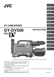
...SC96874-003 For Customer Use : Enter below the Serial No. GY-DV500 Serial No. Before operating this JVC product. Retain this information for purchasing this unit, please read the instructions carefully to ensure the best possible performance. DV CAMCORDER GY-DV500 INTRODUCTION CONTROLS, INDICATORS AND CONNECTORS BASIC SYSTEM CONNECTIONS AND ADJUSTMENTS ... S.S.F. (Super Scene Finder) ,,yy,,yy,,yy USINGEXTERNAL COMPONENTS SETUP MENU FEATURES OF THE CAMERA SECTION OTHERS * The illustration shows the GY-DV500 DV Camcorder with the optional lens viewfinder attached. Model No.
...SC96874-003 For Customer Use : Enter below the Serial No. GY-DV500 Serial No. Before operating this JVC product. Retain this information for purchasing this unit, please read the instructions carefully to ensure the best possible performance. DV CAMCORDER GY-DV500 INTRODUCTION CONTROLS, INDICATORS AND CONNECTORS BASIC SYSTEM CONNECTIONS AND ADJUSTMENTS ... S.S.F. (Super Scene Finder) ,,yy,,yy,,yy USINGEXTERNAL COMPONENTS SETUP MENU FEATURES OF THE CAMERA SECTION OTHERS * The illustration shows the GY-DV500 DV Camcorder with the optional lens viewfinder attached. Model No.
GY-DV500 User Manual - PDF (4,089KB)
Page 4
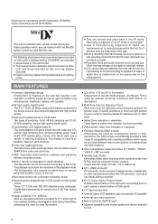
... The following phenomena may occur when tapes recorded on other units (including another GY-DV500) are for private use may infringe on the rights of copyright holders. ● JVC cannot assume liabilities that both video and audio are recorded correctly. ● Recorded... of the format ensures recording and playback with shooting conditions which are for GY-DV500U. This unit is a MiniDV video system format camcorder. Videocassettes which varies as you for purchasing the DV Camcorder GY-DV500. MAIN FEATURES ● Compact, lightweight design Employment of magnesium die cast...
... The following phenomena may occur when tapes recorded on other units (including another GY-DV500) are for private use may infringe on the rights of copyright holders. ● JVC cannot assume liabilities that both video and audio are recorded correctly. ● Recorded... of the format ensures recording and playback with shooting conditions which are for GY-DV500U. This unit is a MiniDV video system format camcorder. Videocassettes which varies as you for purchasing the DV Camcorder GY-DV500. MAIN FEATURES ● Compact, lightweight design Employment of magnesium die cast...
GY-DV500 User Manual - PDF (4,089KB)
Page 6
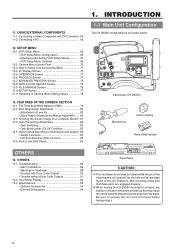
... should be avoided as shown below. OTHERS 14-1 Troubleshooting 86 • Alarm Indications 86 • Warnings in Viewfinder 88 • Troubles with DV Connector 64 11-2 Connecting a PC 65 12. 11. USING EXTERNAL COMPONENTS 11-1 Connecting a Video Component with Error Code Outputs 90 • ...OUTPUT WHT.BAL NG POWER ON OFF OPERATE/WARNING RESET MONITOR SELECT CH-1 AUDIO CH-2 LEVEL LIGHT ON OFF COUNTER CTL TC UB Camcorder (GY-DV500) Microphone CR230V32 Lithium battery Head cleaning tape OTHERS 14. Be sure to Select from the tripod. FEATURES OF THE CAMERA SECTION...
... should be avoided as shown below. OTHERS 14-1 Troubleshooting 86 • Alarm Indications 86 • Warnings in Viewfinder 88 • Troubles with DV Connector 64 11-2 Connecting a PC 65 12. 11. USING EXTERNAL COMPONENTS 11-1 Connecting a Video Component with Error Code Outputs 90 • ...OUTPUT WHT.BAL NG POWER ON OFF OPERATE/WARNING RESET MONITOR SELECT CH-1 AUDIO CH-2 LEVEL LIGHT ON OFF COUNTER CTL TC UB Camcorder (GY-DV500) Microphone CR230V32 Lithium battery Head cleaning tape OTHERS 14. Be sure to Select from the tripod. FEATURES OF THE CAMERA SECTION...
GY-DV500 User Manual - PDF (4,089KB)
Page 18
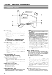
...is obtained and the signal is stabilized. [VTR REMOTE] connector A part of the disturbed video image continues. For details, please consult your JVC dealer. The cover can be set to the VTR REMOTE connector, the VTR Setup Menu is not displayed in the playback mode. •... cable is not possible. The SC phase must be inserted or removed from the unit. 2. CONTROLS, INDICATORS AND CONNECTORS 2-3 Left Side Section q w e r PUSH DV CAMCORDER GY-DV500 Y/C OUT MONITOR OUT LINE OUT CH-1 CH-2 VTR REMOTE SYNC IN TEST OUT MIC IN LENS i u y t 1 Cassette cover Pressing the EJECT switch on...
...is obtained and the signal is stabilized. [VTR REMOTE] connector A part of the disturbed video image continues. For details, please consult your JVC dealer. The cover can be set to the VTR REMOTE connector, the VTR Setup Menu is not displayed in the playback mode. •... cable is not possible. The SC phase must be inserted or removed from the unit. 2. CONTROLS, INDICATORS AND CONNECTORS 2-3 Left Side Section q w e r PUSH DV CAMCORDER GY-DV500 Y/C OUT MONITOR OUT LINE OUT CH-1 CH-2 VTR REMOTE SYNC IN TEST OUT MIC IN LENS i u y t 1 Cassette cover Pressing the EJECT switch on...
GY-DV500 User Manual - PDF (4,089KB)
Page 20
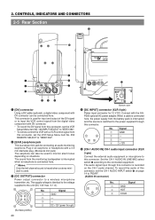
... IN LINE/MIC select switch 8 according to a wireless microphone transmitter, etc. Plug in an earphone or headphone with DV connector can also be connected here. CONTROLS, INDICATORS AND CONNECTORS 2-5 Rear Section !1 PUSH 0 DV CAMCORDER GY-DV500 q w e EARPHONE DV CH-1 AUDIO IN CH-2 LINE MIC LINE MIC DC INPUT +48V ON +48V ON TALLY DC OUTPUT...
... IN LINE/MIC select switch 8 according to a wireless microphone transmitter, etc. Plug in an earphone or headphone with DV connector can also be connected here. CONTROLS, INDICATORS AND CONNECTORS 2-5 Rear Section !1 PUSH 0 DV CAMCORDER GY-DV500 q w e EARPHONE DV CH-1 AUDIO IN CH-2 LINE MIC LINE MIC DC INPUT +48V ON +48V ON TALLY DC OUTPUT...
GY-DV500 User Manual - PDF (4,089KB)
Page 35
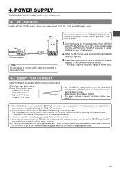
...mount the optional battery holder. When the AA-P250 is disconnected. • Noise to the GY-DV500. The following battery packs. Ⅲ Flat shape type battery pack Ⅲ Anton-Bauer... to the video and audio signals occurs. 4. AC power adapter DC cable EARPHONE DV CH-1 AUDIO IN CH-2 LINE MIC LINE MIC DC INPUT +48V ON +48V...GY-DV500 to OFF, connect the DC cable from the battery pack is being performed. Press the POWER switch of the AA-P250 are muted. ● When operation is continued with AC power supply or battery pack. 4-1 AC Operation Use the JVC...
...mount the optional battery holder. When the AA-P250 is disconnected. • Noise to the GY-DV500. The following battery packs. Ⅲ Flat shape type battery pack Ⅲ Anton-Bauer... to the video and audio signals occurs. 4. AC power adapter DC cable EARPHONE DV CH-1 AUDIO IN CH-2 LINE MIC LINE MIC DC INPUT +48V ON +48V...GY-DV500 to OFF, connect the DC cable from the battery pack is being performed. Press the POWER switch of the AA-P250 are muted. ● When operation is continued with AC power supply or battery pack. 4-1 AC Operation Use the JVC...
GY-DV500 User Manual - PDF (4,089KB)
Page 43
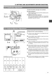
DV CAMCORDER GY-DV500 3.~8. Adjust the CHROMA control of the monitor so that the color bars H and I disappear but J is clearly visible. 3. Set the monitor's BLUE CHECK function ... the OUTPUT switch to BARS to the standard screen (R, G and B will all appear). 8. With the BLUE CHECK function ON, adjust the PHASE control of the GY-DV500. 2. Eyepiece 1. 2. Eyepiece focusing ring 1. 1. White Yellow Cyan Green Magenta Red Blue 1234 Blue Black Magenta Black 890A Black E White F Black G 5 67 Cyan B Black C White...
DV CAMCORDER GY-DV500 3.~8. Adjust the CHROMA control of the monitor so that the color bars H and I disappear but J is clearly visible. 3. Set the monitor's BLUE CHECK function ... the OUTPUT switch to BARS to the standard screen (R, G and B will all appear). 8. With the BLUE CHECK function ON, adjust the PHASE control of the GY-DV500. 2. Eyepiece 1. 2. Eyepiece focusing ring 1. 1. White Yellow Cyan Green Magenta Red Blue 1234 Blue Black Magenta Black 890A Black E White F Black G 5 67 Cyan B Black C White...
GY-DV500 User Manual - PDF (4,089KB)
Page 47
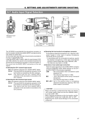
... OFF COUNTER CTL TC UB CH-1 AUDIO CH-2 LEVEL AUTO MANUAL AUDIO SELECT AUDIO INPUT CH-1 CH-2 FRONT REAR CH-1 AUDIO LINE/MIC switch EARPHONE DV CH-1 AUDIO IN CH-2 LINE MIC LINE MIC DC INPUT +48V ON +48V ON TALLY DC OUTPUT CH-2 AUDIO LINE/MIC switch CH-1 AUDIO INPUT... connector CH-2 AUDIO INPUT connector CH-1 AUDIO INPUT switch CH-2 AUDIO INPUT switch The GY-DV500 is provided with the connected microphone, specify the phantom microphone or other type of microphone using the Camera Setup Menu item CAM MIC +48V...
... OFF COUNTER CTL TC UB CH-1 AUDIO CH-2 LEVEL AUTO MANUAL AUDIO SELECT AUDIO INPUT CH-1 CH-2 FRONT REAR CH-1 AUDIO LINE/MIC switch EARPHONE DV CH-1 AUDIO IN CH-2 LINE MIC LINE MIC DC INPUT +48V ON +48V ON TALLY DC OUTPUT CH-2 AUDIO LINE/MIC switch CH-1 AUDIO INPUT... connector CH-2 AUDIO INPUT connector CH-1 AUDIO INPUT switch CH-2 AUDIO INPUT switch The GY-DV500 is provided with the connected microphone, specify the phantom microphone or other type of microphone using the Camera Setup Menu item CAM MIC +48V...

GY-DV500 User Manual - PDF (4,089KB)
Page 59
... Set the counter display to display more than two hours. 59 Note: Time code more than two hours can not be displayed correctly by consumer DV equipment, which has no capability to indicate time code or user's bit data. Ⅲ Reproducing time codes Press the PLAY button. • The... "PB" indicator lights up on the counter display. TIME CODE OPERATION 9-4 Reproducing Time Codes The GY-DV500 incorporates a time code reader. During playback, the time code or user's bit data recorded on the tape is displayed on the display and the...
... Set the counter display to display more than two hours. 59 Note: Time code more than two hours can not be displayed correctly by consumer DV equipment, which has no capability to indicate time code or user's bit data. Ⅲ Reproducing time codes Press the PLAY button. • The... "PB" indicator lights up on the counter display. TIME CODE OPERATION 9-4 Reproducing Time Codes The GY-DV500 incorporates a time code reader. During playback, the time code or user's bit data recorded on the tape is displayed on the display and the...
GY-DV500 User Manual - PDF (4,089KB)
Page 63
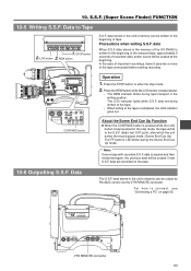
...5 seconds of the tape unrecorded before starting recording. For how to the beginning of tape. Data to the S.S.F. data stored in the memory of the GY-DV500 is written to the tape is kept pressed in the unit's memory can be output by RS-232C control via the VTR REMOTE connector... REGEN AUDIO SELECT FREE REC AUDIO INPUT CH-1 CH-2 CONTINUE MENU FRONT REAR GROUP HOLD ITEM SELECT DATA SET SHIFT ADVANCE PRESET CONTINUE button Operation 1. DV CAMCORDER GY-DV500 Y/C OUT MONITOR OUT LINE OUT CH-1 CH-2 VTR REMOTE SYNC IN TEST OUT MIC IN LENS VTR REMOTE connector 63 In the case of...
...5 seconds of the tape unrecorded before starting recording. For how to the beginning of tape. Data to the S.S.F. data stored in the memory of the GY-DV500 is written to the tape is kept pressed in the unit's memory can be output by RS-232C control via the VTR REMOTE connector... REGEN AUDIO SELECT FREE REC AUDIO INPUT CH-1 CH-2 CONTINUE MENU FRONT REAR GROUP HOLD ITEM SELECT DATA SET SHIFT ADVANCE PRESET CONTINUE button Operation 1. DV CAMCORDER GY-DV500 Y/C OUT MONITOR OUT LINE OUT CH-1 CH-2 VTR REMOTE SYNC IN TEST OUT MIC IN LENS VTR REMOTE connector 63 In the case of...

GY-DV500 User Manual - PDF (4,089KB)
Page 64
...11-1 Connecting a Video Component with DV Connector Rear section of GY-DV500 EARPHONE DV CH-1 AUDIO IN CH-2 LINE MIC LINE MIC DC INPUT +48V ON +48V ON TALLY DC OUTPUT DV connector Video component with DV Connector DV connector DV cable When connecting the GY-DV500 to a non-linear editing ...controller or other component with DV connector, set the VCR Setup Menu item No.050 REMOTE SELECT to "...
...11-1 Connecting a Video Component with DV Connector Rear section of GY-DV500 EARPHONE DV CH-1 AUDIO IN CH-2 LINE MIC LINE MIC DC INPUT +48V ON +48V ON TALLY DC OUTPUT DV connector Video component with DV Connector DV connector DV cable When connecting the GY-DV500 to a non-linear editing ...controller or other component with DV connector, set the VCR Setup Menu item No.050 REMOTE SELECT to "...
GY-DV500 User Manual - PDF (4,089KB)
Page 65
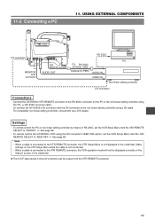
...DV CAMCORDER GY-DV500 DV connector Y/C OUT MONITOR OUT LINE OUT CH-1 CH-2 SYNC IN TEST OUT VTR REMOTE MIC IN LENS VTR REMOTE connector MONITOR OUT connector AUDIO OUT RS-232C TTL RS-232C converter cable (Optional VC-P893) RS-232C AUDIO IN VIDEO IN PC Non-linear editing controller DV... connector Connections Connect the GY-DV500's VTR...-linear editing controller using the DV connector's IEEE1394 option, set the.... • To remote control the GY-DV500's VCR using a DV cable. Note: • When a...Or connect the GY-DV500's DV connector and the DV connector of RS...
...DV CAMCORDER GY-DV500 DV connector Y/C OUT MONITOR OUT LINE OUT CH-1 CH-2 SYNC IN TEST OUT VTR REMOTE MIC IN LENS VTR REMOTE connector MONITOR OUT connector AUDIO OUT RS-232C TTL RS-232C converter cable (Optional VC-P893) RS-232C AUDIO IN VIDEO IN PC Non-linear editing controller DV... connector Connections Connect the GY-DV500's VTR...-linear editing controller using the DV connector's IEEE1394 option, set the.... • To remote control the GY-DV500's VCR using a DV cable. Note: • When a...Or connect the GY-DV500's DV connector and the DV connector of RS...

GY-DV500 User Manual - PDF (4,089KB)
Page 68
... the VTR REMOTE connector on the GY-DV500. * The operation buttons on the GY-DV500 only. BLINK 126: INPUT SELECT vld CAMERA IEEE1394 cA IEEE1394 Selection of the microphone. IEEE1394 : The image from the DV connector equipped video component connected to the DV connector on To select whether or ...the front section recording level control is pressed to reduce the wind noise of the input video signal. Settings cannot be operative. The GY-DV500 does not allow after-recording. 246: FRONT VOLUME ENABLE FruL DISABLE ENABLE oF on the side section works regardless of the ...
... the VTR REMOTE connector on the GY-DV500. * The operation buttons on the GY-DV500 only. BLINK 126: INPUT SELECT vld CAMERA IEEE1394 cA IEEE1394 Selection of the microphone. IEEE1394 : The image from the DV connector equipped video component connected to the DV connector on To select whether or ...the front section recording level control is pressed to reduce the wind noise of the input video signal. Settings cannot be operative. The GY-DV500 does not allow after-recording. 246: FRONT VOLUME ENABLE FruL DISABLE ENABLE oF on the side section works regardless of the ...

GY-DV500 User Manual - PDF (4,089KB)
Page 91
...not shown as onscreen-display. • Video head may not be possible to turn on the GY-DV500 don't work . • Is the VCR Setup Menu item No. 246 FRONT VOLUME ... recording doesn't change the recording level of the level of battery in the • When not connected via the DV connector, is open ? for Use of the power supply may occur due to "TC" or "UB". Recording ... the • The capacity of Head Cleaning Tape".) • Is the sync signal input to "ENABLE". The GY-DV500 remains inoperative as long as on the counter display. If it is set to SAVE, set to the SYNC...
...not shown as onscreen-display. • Video head may not be possible to turn on the GY-DV500 don't work . • Is the VCR Setup Menu item No. 246 FRONT VOLUME ... recording doesn't change the recording level of the level of battery in the • When not connected via the DV connector, is open ? for Use of the power supply may occur due to "TC" or "UB". Recording ... the • The capacity of Head Cleaning Tape".) • Is the sync signal input to "ENABLE". The GY-DV500 remains inoperative as long as on the counter display. If it is set to SAVE, set to the SYNC...
GY-DV500 User Manual - PDF (4,089KB)
Page 96
and many other countries. © 1999 VICTOR COMPANY OF JAPAN, LIMITED Printed in Japan, the U.S.A., the U.K. VICTOR COMPANY OF JAPAN, LIMITED ® is a registered trademark owned by VICTOR COMPANY OF JAPAN, LTD. ® is a registered trademark in Japan SC96874-003 GY-DV500 @DV CAMCORDER
and many other countries. © 1999 VICTOR COMPANY OF JAPAN, LIMITED Printed in Japan, the U.S.A., the U.K. VICTOR COMPANY OF JAPAN, LIMITED ® is a registered trademark owned by VICTOR COMPANY OF JAPAN, LTD. ® is a registered trademark in Japan SC96874-003 GY-DV500 @DV CAMCORDER


