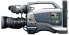
Using Streamcapture / Internet Explorer with a Microsoft® Media Server
Page 1
JVC PROFESSIONAL PRODUCTS COMPANY Subject: Application Note 5 Using Streamcapture/Internet Explorer with a Microsoft® Media Server This application note applies to both the GY-DV300/KA-DV300 and GY-DV5000/KADV5000 Streamcorders Although it to port 2170. This can be illustrated here. This is a method ... and operating system documentation for streaming from a single GY-DV300/KADV300 or GY-DV5000/KA-DV5000. The button turns from the factory default of 4 Please refer to stop the video display. Click on the server. 1. The cameras address has been set to another free port. After...
DR-DV5000U DV Video Disk Recorder 44 page instruction manual
Page 22
... when camcorder FireStore DR-DV5000 User Guide is for use this mode, the GY-DV5000 camcorder must be in VTR Mode and a record inhibit tape must be available disk space on the tape is set to SAVE, the camera is...is the period of time between DR-DV5000's capture of a single frame of video (a value of 00:00:01:00 means one frame will appear on the DR-DV5000 LCD display if no tape is present,..., on the DR-DV5000 LCD display if no audio will be released at the beginning of up to 59. EXIT will display "DUMP INHIBIT". In order to use with JVC GYDV5000 series camcorders only. Tape will ...
GY-DV5000U 3-CCD Professional DV Camcorder 92 page instruction manual
Page 4
...AUDIO/VIDEO Menu Screen 72 11-10 LCD/VF Menu Screen 73 11-11 TC/UB/CLOCK Menu Screen 75 11-12 TIME/DATE Menu Screen 76 11-13 OTHERS Menu Screen 77 12. Videocassettes marked with shooting conditions which varies as you for purchasing the DV Camcorder GY-DV5000. Tapes... of digital data to other equipment provided with DV connector, such as a non-linear editing system. ● 1/2" bayonet type lens ● Camera output, VCR playback output (composite/YC) possible ● Built-in color bar (SMPTE type) ● Superior operability with 3-CCD system for reproduction of Time Code 62 10...
GY-DV5000U 3-CCD Professional DV Camcorder 92 page instruction manual
Page 5
...skill and equipment, please consult the person in charge of professional video equipment at a temperature or humidity outside the allowable ranges ... JVC-authorized service agent. Be sure to clean the camera after the power is turned on, but the impact on the AUDIO/ VIDEO...CCD elements could be disturbed during playback, edit search, and recording check using high-precision technology. If the power voltage is displayed and correct playback will collect dirt, wear out and deteriorate as routine maintenance. INTRODUCTION 1-2 Routine and Periodical Maintenance The GY-DV5000...
GY-DV5000U 3-CCD Professional DV Camcorder 92 page instruction manual
Page 6
...Video tape Do not leave the videocassette inserted when moving the camera under conditions where the temperature of a CCD it to 35˚C). Another effect is exposed directly to the head drum or tape guides and be Used The GY-DV5000...half of white dots in noise caused by dropouts, etc. Standard DV videocassette: LA-DV276, LA-DV186, LADV124 Mini DV videocassette: M-DV63PRO, M-DV60, M-DV30 * Do not use . .... Nevertheless, please take note that of the cleaning tape. This is characterized by JVC. INTRODUCTION 1-3 Precautions for each cleaning. 4. The tape runs for 10 seconds at...
GY-DV5000U 3-CCD Professional DV Camcorder 92 page instruction manual
Page 11
...OUT CH-2 o 1 [TALLY] Tally lamp This lamp lights up when the GY-DV5000 enters the record mode. Set the AUDIO MONITOR item on tape. nal is adjusted with DV connector can be performed. CONTROLS, INDICATORS AND CONNECTORS MEMO: ● The volume...Camera mode: The DV compressed signal (IEEE1394) of the camera image is a stereo mini-jack for connecting an earphone for power output to the optional AA-P250 power adapter. Signal 1 GND 2 HOT 3 COLD 3 [DC IN] DC input connector (XLR 4-pin) Power input connector for output of professional video equipment at your nearest JVC...
GY-DV5000U 3-CCD Professional DV Camcorder 92 page instruction manual
Page 16
...6 [TALLY] switch Set this light from turning on the camera. 3 Connector Connect to the camera. 4 [CONT] contrast adjustment To adjust the contours of the...VIDEO LIGHT (ANTON BAUER. Please use the Focus Manual Unit (FMM-8, CHF-3, CFC-12-990) manufactured by Fujinon. 28 29 BASIC SYSTEM CONNECTIONS AND ADJUSTMENTS 3-1 Basic System * For information on connection with the FRONT TALLY item on page 30. 8 9 3. PROTEC) 1.5" VIEW FINDER VF-P115B VF-P116 DV CAMCORDER... AUDIO SELECT CH-1 CH-2 AUTO MANUAL DISPLAY PULL OPEN GY-DV5000 STANDARD PACKAGE TRIPOD BASE KA-550U FOCUS MANUAL UNIT HZ-...
GY-DV5000U 3-CCD Professional DV Camcorder 92 page instruction manual
Page 18
...may occur if the DC cable is supplied to the video and audio signals occurs. Attach the tripod base on the tripod by using the hole that these parts are set to place the camera on the rear base mount of the GY-DV5000 as the AC power supply. Therefore, after the ...battery pack capacity has been used . 32 33 POWER SUPPLY The GY-DV5000 is necessary to the GY-DV5000. AA-P250 AC power adapter DC cable PHONES DV REAR AUDIO IN DC OUT...
GY-DV5000U 3-CCD Professional DV Camcorder 92 page instruction manual
Page 25
... maximum telephoto position. 5. Brightness and contrast adjustment When the ambient brightness changes, etc., the brightness and contrast of the GY-DV5000. 2. Connect a color video monitor to a darker place. 4. Set the monitor's BLUE CHECK function to ON while the color bars are being displayed...the best possible focus. 9. If the illumination is no difference in color bar signal on the CAMERA OPERATION menu screen (4:3 or LETTER). 6-4 External Monitor Adjustment PUSH Color video monitor 1. 3.~8. Siemens star chart 47 BRIGHT 1. Adjust the position and angle of the monitor ...
GY-DV5000U 3-CCD Professional DV Camcorder 92 page instruction manual
Page 29
...Mode (Recording Check Function) RET button This function is available only when the GY-DV5000 is reengaged. After playback is finished, the tape returns to check the recorded scene or continue recording from the scene. The camera will appear if the error rate increases due to protect the tape. (...record-standby mode. ■ Searching the tape in the viewfinder or on a monitor connected to the MONITOR OUT or Y/C OUT connectors. ● The video image from the VTR section is possible to the MONITOR OUT or Y/C OUT connectors. 1. In the record-standby mode, approximately 2 seconds of the ...
GY-DV5000U 3-CCD Professional DV Camcorder 92 page instruction manual
Page 30
...MODE VTR CAM Still button PLAY button STOP button POWER switch MODE switch MEMO: ● The GY-DV5000 can be selected with the TEST TONE item on the upper section of videocassettes: • DV videocassette • MiniDV videocassette • DVCAM videocassette ● Tapes recorded in the viewfinder. (... Following loading of the unit to the VTR mode. MEMO: ● In the VTR mode, the camera image is not output on the LCD monitor, in the viewfinder or through the video output connector. ● The VTR mode is loaded, the unit enters the Stop mode. 4. SHOOTING OPERATION...
GY-DV5000U 3-CCD Professional DV Camcorder 92 page instruction manual
Page 32
...; If block noise appears or the sound falls out, try to stop recording, and then stop of the GY-DV5000's Camera Image and Sound Through the DV Connector The GY-DV5000's camera image and sound can be heard momentarily from the EDIT SEARCH or PLAYBACK mode to set "REMOTE SELECT". ...OPEN MODE VTR CAM MODE switch ● Dubbing still images makes the images coarser. USING EXTERNAL COMPONENTS 9-1 Connecting a Video Component with DV Connector Connecting the GY-DV5000 to another component that is changed, noise may appear in accordance with the operation of BR-DV600A or BR-DV3000 ...
GY-DV5000U 3-CCD Professional DV Camcorder 92 page instruction manual
Page 33
...SELECT CH-1 CH-2 AUTO MANUAL DISPLAY PULL OPEN SHUTTER dial STATUS button TOP MENU screen --- CAMERA OPERATION.. OTHERS.. The blinking digit is rotated, the value of frames per 1 second is ... (Colon or dot) UB : User's bit data is rotated upward, the value becomes higher. AUDIO/VIDEO.. LCD/VF.. Set the time code (hours, minutes, seconds, frames). 1 Rotate the SHUTTER dial to...SHUTTER dial. ● The first digit of the data during recording. TIME CODE OPERATION The GY-DV5000 records SMPTE-standard time codes and user's bits. PRST REC : The data preset in the ...
GY-DV5000U 3-CCD Professional DV Camcorder 92 page instruction manual
Page 34
...CANCEL EXIT TOP MENU screen (CAM) --- FILE MANAGE.. PAGE BACK CAMERA PROCESS screen --- OUTPUT CHAR. CLOCK ADJUST --- TC GENE switch 10-4 Reproducing Time Codes The GY-DV5000 incorporates a time code reader. CAMERA OPERATION.. AUDIO/VIDEO.. TC/UB/CLOCK.. CINE MODE OFF COLOR MATRIX STD GAMMA NORMAL ...the tape is displayed on the LCD monitor or in the GYDV5000's memory and are identical to be displayed correctly by DV components for general consumer use, as some of the existing data. DISPLAY ON DISPLAY MODE BARS+CAM DATE REC OFF ...
GY-DV5000U 3-CCD Professional DV Camcorder 92 page instruction manual
Page 35
... ● To close the FILE MANAGE menu screen: Align the cursor ( ) with the PAGE BACK item, and then press the SHUTTER dial. CAMERA OPERATION.. AUDIO/VIDEO.. MENU ALL RESET CANCEL EXIT Select the FILE MANAGE item on other menu screens, repeat the procedures in the setting value area blinks. --- Storing... menu settings stored in FILE CAM1 or CAM2, select the FILE MANAGE menu screen and perform the operations for saving to CANCEL, none of the GY-DV5000 with the LOAD FILE, and then press the SHUTTER dial. ● The area for 1 second or longer. ● The TOP MENU screen appears. ...
GY-DV5000U 3-CCD Professional DV Camcorder 92 page instruction manual
Page 36
...-4 TOP MENU Screen Different menu screens are displayed depending on whether the GY-DV5000 is in the Camera mode or in the Camera mode. ----- ----- The ways that the date and time are set in the Camera mode. ----- ----- Item Function Variation Range Initial Setting SHUTTER The SHUTTER...LETTER :LETTER BOX (16:9 aspect ratio) image output. ● When setting DATE REC in place of the video signal. 4:3 4:3 RATIO 4:3 :4:3 aspect ratio image output. CAMERA PROCESS Displays a menu screen for setting the time code, user's bit data, date and time. FILE MANAGE ...
GY-DV5000U 3-CCD Professional DV Camcorder 92 page instruction manual
Page 38
...11-9 AUDIO/VIDEO Menu Screen ...frequency 48K : Recording is performed with 16-bit, 48 kHz sampling frequency * The DV format offers recording tracks for recording. * This setting is not displayed. Selects whether or...: Not displayed NORMAL : 4:3 zone is displayed. 16:9 : 16:9 zone is displayed. The GY-DV5000 records two of the CH-3 and CH-4 channels. DISABLE ENABLE ENABLE To select whether or not the...the sound recorded on the side section is output from L and R) Selects whether the camera image or VTR playback image should be operative. Use this setting. CH1/2 MIX CH3...
GY-DV5000U 3-CCD Professional DV Camcorder 92 page instruction manual
Page 40
... BARS: Date and time are shown in the status display on the tape as video data or not, as well as the video mode in the time display. DATE+TIME: Date and time are output. When ...network pack. ON : Displayed. BARS+CAM: Date and time data are recorded when color bars and camera image are not displayed. LONG PAUSE TIME Selects the time (minutes) before the tape protect mode (drum... ----- TIME: Time only is executed. When the DISPLAY item is set to ON when the GY-DV5000's DV signal should be ON recorded on the menu. 3MIN 30MIN 30MIN REM FF/REW MODE Selects the...
GY-DV5000U 3-CCD Professional DV Camcorder 92 page instruction manual
Page 45
...13-1 Alarm Indications and Actions The GY-DV5000 displays messages on the LCD monitor and in the viewfinder in the LP mode. A data tape for video use is a microcomputer-controlled piece of... viewfinder or LCD monitor. clogging is loaded. videocassette for PC or DVCPRO videocassette Use a standard DV videocassette or MiniDV use . Insert a videocassette. ● Alarm area (Display area: B) Indication...monitor and in the colour tone areas adjusted with a new tape immediately. FEATURES OF THE CAMERA SECTION 12-7 How to the "SKIN AREA" side, zebra patterns are indicated in the Viewfinder...
GY-DV5000U 3-CCD Professional DV Camcorder 92 page instruction manual
Page 46
... Indications and Actions (Cont'd) ● Warning Indications for the camera to take out the cassette. 5702 TAPE END DET. Error code WARNING7001 DRUM MOTOR FAILURE Warning Error Code Error Details GY-DV5000 Operation Remedy 0201 Indicates dew formation Operation stops. However, the ...the interval where the unit switches from the monitoring loudspeaker and the PHONES jack. (In Camera mode only) When an irregularity occurs in charge of professional video equipment at your nearest JVC-authorized service agent. 7202 ~ 7203 Supply reel rotation error. Tape end (displayed during...