Instructions
Page 2
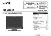
... (servicing) instructions in the literature accompanying the appliance. DT-V17L2D MULTI FORMAT LCD MONITOR CAUTION RISK OF ELECTRICAL SHOCK DO NOT OPEN CAUTION: To reduce the risk of Contents Safety Precautions 2 IMPORTANT SAFEGUARDS 2 Maintenance 3 Installation 4 Daily Operations / Connections 6 Front panel 6 Rear panel 8 Available signals 9 Menu Configuration-MAIN MENU 10 Menu Configuration-SET-UP MENU 12 External Control 14 About the external control 14 Using the MAKE/TRIGGER system 14 Using the serial...
... (servicing) instructions in the literature accompanying the appliance. DT-V17L2D MULTI FORMAT LCD MONITOR CAUTION RISK OF ELECTRICAL SHOCK DO NOT OPEN CAUTION: To reduce the risk of Contents Safety Precautions 2 IMPORTANT SAFEGUARDS 2 Maintenance 3 Installation 4 Daily Operations / Connections 6 Front panel 6 Rear panel 8 Available signals 9 Menu Configuration-MAIN MENU 10 Menu Configuration-SET-UP MENU 12 External Control 14 About the external control 14 Using the MAKE/TRIGGER system 14 Using the serial...
Instructions
Page 3
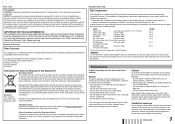
... not use this product near the window • Do not place this product through openings as they may be hazardous. • When replacement parts are required, be mounted according to . • All operating instructions should be sure the service technician has used replacement parts specified by plugging/unplugging the power cord into this product, ask the service technician to perform safety checks to replace the fuse Open the...
... not use this product near the window • Do not place this product through openings as they may be hazardous. • When replacement parts are required, be mounted according to . • All operating instructions should be sure the service technician has used replacement parts specified by plugging/unplugging the power cord into this product, ask the service technician to perform safety checks to replace the fuse Open the...
Instructions
Page 4
... around the intakes (all the openings). This equipment generates, uses, and can be caused by inappropriate waste handling of this product, please visit our web page www.jvc-europe.com to obtain information about the following length: Cable Power cord (attached cable (H05VV-F 3 x 0.75 mm2)) Video signal cable (coaxial cable) Audio signal cable (shielded cable) DVI cable (shielded cable) RS-232C cable (shielded cable) (A straight cable with the provisions and protection...
... around the intakes (all the openings). This equipment generates, uses, and can be caused by inappropriate waste handling of this product, please visit our web page www.jvc-europe.com to obtain information about the following length: Cable Power cord (attached cable (H05VV-F 3 x 0.75 mm2)) Video signal cable (coaxial cable) Audio signal cable (shielded cable) DVI cable (shielded cable) RS-232C cable (shielded cable) (A straight cable with the provisions and protection...
Instructions
Page 5
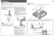
... adjust the stand height" on the monitor) Screw holes for stand attachment Monitor Guidelines CAUTION • Be careful not to 0°, then attach the removed screws. When installing the stand to the monitor, insert the guides of the stand into the guide holes on the monitor to place the stand on the monitor or lean against the monitor. • Do not touch the LCD panel when installing the monitor. • Make sure to install the monitor securely...
... adjust the stand height" on the monitor) Screw holes for stand attachment Monitor Guidelines CAUTION • Be careful not to 0°, then attach the removed screws. When installing the stand to the monitor, insert the guides of the stand into the guide holes on the monitor to place the stand on the monitor or lean against the monitor. • Do not touch the LCD panel when installing the monitor. • Make sure to install the monitor securely...
Instructions
Page 6
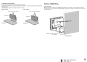
... Fix the monitor to a wall or a pillar using durable string. Stand plate Stand plate Stand body Stand body Hook and screws (M4 x 10 mm) (not provided) Hook (not provided) ENGLISH 5 To adjust the stand height You can select the stand height-higher position or lower position. Fixing the monitor Attach the hook (not provided) to the VESA mounting holes on the rear panel (use the two holes on page 4. To change the stand height, change the position of the monitor to a wall by using...
... Fix the monitor to a wall or a pillar using durable string. Stand plate Stand plate Stand body Stand body Hook and screws (M4 x 10 mm) (not provided) Hook (not provided) ENGLISH 5 To adjust the stand height You can select the stand height-higher position or lower position. Fixing the monitor Attach the hook (not provided) to the VESA mounting holes on the rear panel (use the two holes on page 4. To change the stand height, change the position of the monitor to a wall by using...
Instructions
Page 7
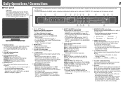
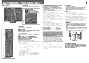
..." in the following order. Lights in "SYNC FUNCTION" on page 11). SAVE (power save) mode (☞ "NO SYNC ACTION" in Green: The monitor is not available for the selected input lights. Normal screen Red screen Blue screen Green screen t ASPECT button/lamp Changes the aspect ratio of the picture from green. CONTRAST: Adjusts the picture contrast. 4 MUTING button Turns off (on standby) the monitor. • The power switches (POWER and DC) are turned off the DC switch on the rear panel before replacing the battery. •...
..." in the following order. Lights in "SYNC FUNCTION" on page 11). SAVE (power save) mode (☞ "NO SYNC ACTION" in Green: The monitor is not available for the selected input lights. Normal screen Red screen Blue screen Green screen t ASPECT button/lamp Changes the aspect ratio of the picture from green. CONTRAST: Adjusts the picture contrast. 4 MUTING button Turns off (on standby) the monitor. • The power switches (POWER and DC) are turned off the DC switch on the rear panel before replacing the battery. •...
Instructions
Page 8
... menu. For some items, adjustments will overlap with HDCP is input. • "NO SYNC" is displayed when no time code, "TC is displayed. 5 CRC error indication ☞ "CRC ERROR" in from the speakers (L/R) and the MONITOR OUT (L/R) terminals, when EMBEDDED AUDIO signals come in "INFORMATION" on the monitor 1 Signal format • "*" is displayed at the end of the indication when a DVI-D signal protected with higher resolution than a computer, the picture...
... menu. For some items, adjustments will overlap with HDCP is input. • "NO SYNC" is displayed when no time code, "TC is displayed. 5 CRC error indication ☞ "CRC ERROR" in from the speakers (L/R) and the MONITOR OUT (L/R) terminals, when EMBEDDED AUDIO signals come in "INFORMATION" on the monitor 1 Signal format • "*" is displayed at the end of the indication when a DVI-D signal protected with higher resolution than a computer, the picture...
Instructions
Page 9
... when the monitor is not displayed correctly, change the setting of the current EMBEDDED AUDIO signals in P.SAVE (power save ) mode. 8 DVI-D (HDCP) terminal Input terminal for example, when unplugging the AC power cord), the power supply automatically switches to the DC 12 V power supply. To save battery life, turn off (for the DVI-D signal. • When the picture is on standby. Ferrite core * Using the audio level meter You can check the conditions of "DVI INPUT SEL." (☞...
... when the monitor is not displayed correctly, change the setting of the current EMBEDDED AUDIO signals in P.SAVE (power save ) mode. 8 DVI-D (HDCP) terminal Input terminal for example, when unplugging the AC power cord), the power supply automatically switches to the DC 12 V power supply. To save battery life, turn off (for the DVI-D signal. • When the picture is on standby. Ferrite core * Using the audio level meter You can check the conditions of "DVI INPUT SEL." (☞...
Instructions
Page 10
... terminal Cover 3 CAUTION • Use only the provided screws. • Make sure the plug will become obscured because their signal resolution is higher than the screen resolution (1440 x 900). • Non-preset signals may not be displayed normally even if its plug and pull it out. • DO NOT connect the power cord until all the equipment. • Use a cord whose plugs correctly match the terminals on sync signals. Input signal 1 T.M.D.S Data...
... terminal Cover 3 CAUTION • Use only the provided screws. • Make sure the plug will become obscured because their signal resolution is higher than the screen resolution (1440 x 900). • Non-preset signals may not be displayed normally even if its plug and pull it out. • DO NOT connect the power cord until all the equipment. • Use a cord whose plugs correctly match the terminals on sync signals. Input signal 1 T.M.D.S Data...

Instructions
Page 11
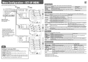
... frequency of the luminance signal compensated in about 30 seconds after the previous operation. • Some items may not appear on the menu depending on the input or the input signal. • The items controlled by using external control (☞ "External Control" on the menu. BACK LIGHT Setting value: -20 - +20 Adjusts the brightness of "PICTURE IMPROVEMENT" while viewing the actual picture. DVI INPUT SEL. Setting value: AUTO, MODE1, MODE2 When "AUTO" is compatible...
... frequency of the luminance signal compensated in about 30 seconds after the previous operation. • Some items may not appear on the menu depending on the input or the input signal. • The items controlled by using external control (☞ "External Control" on the menu. BACK LIGHT Setting value: -20 - +20 Adjusts the brightness of "PICTURE IMPROVEMENT" while viewing the actual picture. DVI INPUT SEL. Setting value: AUTO, MODE1, MODE2 When "AUTO" is compatible...

Instructions
Page 12
... "P.SAVE" saves more power consumption by half. (The screen color changes to display the picture (low latency function). • If the picture is not displayed steadily while "ON" is selected, select "OFF." • While "ON" is selected, the displayed picture may not appear on the menu depending on the input or the input signal. • The items controlled by the MAKE system do Select the screen status when no audio signal input...
... "P.SAVE" saves more power consumption by half. (The screen color changes to display the picture (low latency function). • If the picture is not displayed steadily while "ON" is selected, select "OFF." • While "ON" is selected, the displayed picture may not appear on the menu depending on the input or the input signal. • The items controlled by the MAKE system do Select the screen status when no audio signal input...
Instructions
Page 13
... "sub menu POSI." LOWER2: Displays the current setting at the lower part of each color (R/G/B). Item To do Setting value H SIZE*2 Adjust the horizontal picture size. Adjusts the size and position of the screen. V SIZE*2 Adjust the vertical picture size. ADJ." MAX (in "SIZE/POSI. Setting value ☞ "NOTE" AUTO, NTSC, PAL GREEN, RED 12 PICTURE SUB ADJ. NTSC SETUP Select the set -up signal) COMPO. SIZE/POSI. Item To do Setting value CONTRAST*1 Adjust the standard level for the brightness -20 - +20 adjusted with "AUTO...
... "sub menu POSI." LOWER2: Displays the current setting at the lower part of each color (R/G/B). Item To do Setting value H SIZE*2 Adjust the horizontal picture size. Adjusts the size and position of the screen. V SIZE*2 Adjust the vertical picture size. ADJ." MAX (in "SIZE/POSI. Setting value ☞ "NOTE" AUTO, NTSC, PAL GREEN, RED 12 PICTURE SUB ADJ. NTSC SETUP Select the set -up signal) COMPO. SIZE/POSI. Item To do Setting value CONTRAST*1 Adjust the standard level for the brightness -20 - +20 adjusted with "AUTO...
Instructions
Page 14
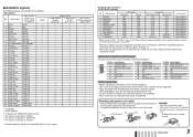
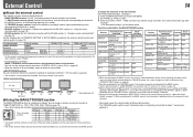
... cannot change the assignment of these functions.) Setting value RS232C, RS485 MAKE, TRIGGER, SET COLOR OFF, ASPECT, A.MARKER, S.MARKER, TIME CODE, 1:1, SCR CHECK, I/P MODE, SDI 1, SDI 2, DVI, COMPONENT, VIDEO, TALLY SEL, SOURCE ID, MUTING, MARK.SEL, L.METER, STATUS, - - - (no function) INFORMATION Setting for the information display of the monitor Item POSITION SOURCE ID CHARACTER SET.*1 STATUS DISPLAY CRC ERROR SUB HOUR METER MODEL VERSION To do Select the input terminal used for...
... cannot change the assignment of these functions.) Setting value RS232C, RS485 MAKE, TRIGGER, SET COLOR OFF, ASPECT, A.MARKER, S.MARKER, TIME CODE, 1:1, SCR CHECK, I/P MODE, SDI 1, SDI 2, DVI, COMPONENT, VIDEO, TALLY SEL, SOURCE ID, MUTING, MARK.SEL, L.METER, STATUS, - - - (no function) INFORMATION Setting for the information display of the monitor Item POSITION SOURCE ID CHARACTER SET.*1 STATUS DISPLAY CRC ERROR SUB HOUR METER MODEL VERSION To do Select the input terminal used for...
Instructions
Page 15
... (RJ-45): Controls the monitor with the RS-485 system. (☞ "Using the serial communication" on page 7). A.MARKER The area marker Off On display S.MARKER The safety marker Off On display TIME CODE Time code display Off On 1:1 Displays in "REMOTE SETTING" (☞ "PIN1, PIN2, PIN3, PIN4, PIN5" on page 7 - - - VIDEO Changes the input Invalid Valid to . This function cannot be controlled Opening Shortcircuiting COLOR OFF Color off Off...
... (RJ-45): Controls the monitor with the RS-485 system. (☞ "Using the serial communication" on page 7). A.MARKER The area marker Off On display S.MARKER The safety marker Off On display TIME CODE Time code display Off On 1:1 Displays in "REMOTE SETTING" (☞ "PIN1, PIN2, PIN3, PIN4, PIN5" on page 7 - - - VIDEO Changes the input Invalid Valid to . This function cannot be controlled Opening Shortcircuiting COLOR OFF Color off Off...
Instructions
Page 16
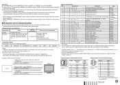
... 4 ! * **1 B I D R E T Cr Starts communication (connection) Terminates communication (termination) Assigns the control ID Initializes the control ID No data No data 01 - 99 No data 5 ! * **1 B I D D S P x x*2 Cr Displays/hides the ID 00: Hide 01: Display 6 ! * **1 B I S P Cr 21 ! * **1 B A M U T E x x*2 Cr 22 ! * **1 B A S P x x*2 Cr Makes setting/adjustment ( ) Makes setting/adjustment ( ) Displays the SET-UP MENU Turns on the monitor Turns off (on standby) Selects "SDI 1" input Selects "SDI 2" input Selects "DVI" input Selects "COMPO." The initial setting of the monitor's ID...
... 4 ! * **1 B I D R E T Cr Starts communication (connection) Terminates communication (termination) Assigns the control ID Initializes the control ID No data No data 01 - 99 No data 5 ! * **1 B I D D S P x x*2 Cr Displays/hides the ID 00: Hide 01: Display 6 ! * **1 B I S P Cr 21 ! * **1 B A M U T E x x*2 Cr 22 ! * **1 B A S P x x*2 Cr Makes setting/adjustment ( ) Makes setting/adjustment ( ) Displays the SET-UP MENU Turns on the monitor Turns off (on standby) Selects "SDI 1" input Selects "SDI 2" input Selects "DVI" input Selects "COMPO." The initial setting of the monitor's ID...
Instructions
Page 17
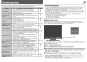
... SET-UP MENU. Wrong color, no image may be a case that a few pixels may flash and no color The picture becomes blurred. The LCD display is not a malfunction. • The red spots, blue spots and green spots on the panel surface are not available for a long time, it off the POWER switch or DC switch on the monitor do not appear on No sound "OTHERS" or "Out of the connected...
... SET-UP MENU. Wrong color, no image may be a case that a few pixels may flash and no color The picture becomes blurred. The LCD display is not a malfunction. • The red spots, blue spots and green spots on the panel surface are not available for a long time, it off the POWER switch or DC switch on the monitor do not appear on No sound "OTHERS" or "Out of the connected...
Instructions
Page 18
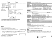
... (auto termination). Specifications 7 General Model name Type Screen size Aspect ratio LCD panel Effective screen size Number of pixels displayed Number of colors displayed Viewing angle (TYP.) Panel brightness (at least) (TYP.) Contrast ratio (TYP.) Horizontal/vertical frequency (computer signal) Compliant video signal format Format Audio output Operating conditions Power requirements Rated current External dimensions (excluding protruding parts) Weight Accessories DT-V17L2D Multi format LCD monitor Type 17 wide format 16:10 17˝ wide, active matrix TFT Width: 367.2 mm Height...
... (auto termination). Specifications 7 General Model name Type Screen size Aspect ratio LCD panel Effective screen size Number of pixels displayed Number of colors displayed Viewing angle (TYP.) Panel brightness (at least) (TYP.) Contrast ratio (TYP.) Horizontal/vertical frequency (computer signal) Compliant video signal format Format Audio output Operating conditions Power requirements Rated current External dimensions (excluding protruding parts) Weight Accessories DT-V17L2D Multi format LCD monitor Type 17 wide format 16:10 17˝ wide, active matrix TFT Width: 367.2 mm Height...

Instructions
Page 19
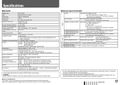
Specifications (cont.) 7 Dimensions Unit: mm 395 86 40 1.5 VESA mounting holes (4-M4, depth: 10 mm) 100 18 100 344.6*/309.6** 304 115 300 * at the higher position ** at the lower position 64 243
Specifications (cont.) 7 Dimensions Unit: mm 395 86 40 1.5 VESA mounting holes (4-M4, depth: 10 mm) 100 18 100 344.6*/309.6** 304 115 300 * at the higher position ** at the lower position 64 243

