Instruction Manual
Page 2
... the Electronics Industries Alliance: Ⅵ PRECAUTIONS ● Use only the power source specified on screen. When the unit is not recommended to keep a certain still image displayed on screen for a Class A digital device, pursuant to Part 15 of certification, and must therefore no user-serviceable parts inside the unit. This problem does not occur as far as displaying extremely bright images on the unit. (120 V/230 V AC...
... the Electronics Industries Alliance: Ⅵ PRECAUTIONS ● Use only the power source specified on screen. When the unit is not recommended to keep a certain still image displayed on screen for a Class A digital device, pursuant to Part 15 of certification, and must therefore no user-serviceable parts inside the unit. This problem does not occur as far as displaying extremely bright images on the unit. (120 V/230 V AC...
Instruction Manual
Page 3
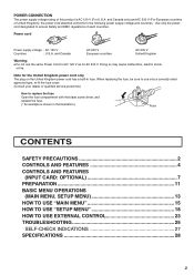
... illustration.) Fuse CONTENTS SAFETY PRECAUTIONS 2 CONTROLS AND FEATURES 4 CONTROLS AND FEATURES (INPUT CARD: OPTIONAL 7 PREPARATION 11 BASIC MENU OPERATIONS (MAIN MENU, SETUP MENU 13 HOW TO USE "MAIN MENU 15 HOW TO USE "SETUP MENU 18 HOW TO USE EXTERNAL CONTROL 23 TROUBLESHOOTING 25 SELF-CHECK INDICATIONS 27 SPECIFICATIONS 28 3 Use only the power cord designated to replace the fuse Open the fuse compartment with the blade screw driver, and replace the fuse. (* An example is...
... illustration.) Fuse CONTENTS SAFETY PRECAUTIONS 2 CONTROLS AND FEATURES 4 CONTROLS AND FEATURES (INPUT CARD: OPTIONAL 7 PREPARATION 11 BASIC MENU OPERATIONS (MAIN MENU, SETUP MENU 13 HOW TO USE "MAIN MENU 15 HOW TO USE "SETUP MENU 18 HOW TO USE EXTERNAL CONTROL 23 TROUBLESHOOTING 25 SELF-CHECK INDICATIONS 27 SPECIFICATIONS 28 3 Use only the power cord designated to replace the fuse Open the fuse compartment with the blade screw driver, and replace the fuse. (* An example is...
Instruction Manual
Page 4
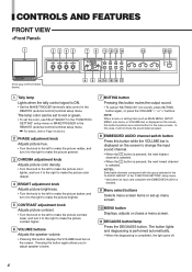
... to adjust speaker volume. ! ! 7 MUTING button Pressing this button displays the VOLUME level bar on the screen to red or green. • To set to change the input sound channel. • When the button is pressed, the next highest channel is selected. • When the button is pressed, the next lowest channel is completed, the light goes off. 4 NOTE: When a menu or setting item (such as a control button for the menu screen. The lamp color...
... to adjust speaker volume. ! ! 7 MUTING button Pressing this button displays the VOLUME level bar on the screen to red or green. • To set to change the input sound channel. • When the button is pressed, the next highest channel is selected. • When the button is pressed, the next lowest channel is completed, the light goes off. 4 NOTE: When a menu or setting item (such as a control button for the menu screen. The lamp color...

Instruction Manual
Page 5
... pressed while lit, the light goes off and the normal screen is invalid with the RGB-input screen. 13 PULSE CROSS button/lamp When you must change the "AREA MARKER" Menu settings first. INPUT C Selected input VIDEO Input card status (*1) NTSC Signal format (*2) HIGH Setting of "COLOR TEMP." (*3) EXT SYNC External synchronization (*4) *1 Notes • "NO SLOT" is displayed when there is no video signal is input. • When "SYNC SELECT" is set to "INT." (internal synchronization...
... pressed while lit, the light goes off and the normal screen is invalid with the RGB-input screen. 13 PULSE CROSS button/lamp When you must change the "AREA MARKER" Menu settings first. INPUT C Selected input VIDEO Input card status (*1) NTSC Signal format (*2) HIGH Setting of "COLOR TEMP." (*3) EXT SYNC External synchronization (*4) *1 Notes • "NO SLOT" is displayed when there is no video signal is input. • When "SYNC SELECT" is set to "INT." (internal synchronization...
Instruction Manual
Page 6
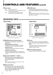
... of DT-V1910CG shown) 21 REMOTE (external control) terminals Terminals for details. 25 Built-in speaker (monaural) Outputs the selected INPUT audio signal. MAKE/TRIGGER terminal (Upper): Enables the monitor to be controlled by closing the circuit (point of contact) connected to the IN terminal. 22 Input card slots (SLOT 1 - Input cards are installed. 23 Main power switch Press the switch to turn the main power ON or OFF. REAR/SIDE VIEW...
... of DT-V1910CG shown) 21 REMOTE (external control) terminals Terminals for details. 25 Built-in speaker (monaural) Outputs the selected INPUT audio signal. MAKE/TRIGGER terminal (Upper): Enables the monitor to be controlled by closing the circuit (point of contact) connected to the IN terminal. 22 Input card slots (SLOT 1 - Input cards are installed. 23 Main power switch Press the switch to turn the main power ON or OFF. REAR/SIDE VIEW...

Instruction Manual
Page 7
... the connection terminal of your Multi-Format Monitor. Ⅵ VIDEO INPUT CARD (IF-C01PNG) VIDEO 1 IN OUT VIDEO 2 1 IN OUT Y/C IN 2 EXT.SYNC 3 IN OUT AUDIO 1 IN OUT 4 AUDIO 2 5 Ⅵ Compatible signal formats: NTSC (3.58 MHz), PAL (4.43 MHz), black-and-white (50 Hz/60 Hz) 1 Composite signal input/output terminals (VIDEO 1, VIDEO 2) Input (IN) and output (OUT) terminals for component (color difference) or RGB signals. To use these terminals, set "SYNC SELECT" to "SYNC SELECT...
... the connection terminal of your Multi-Format Monitor. Ⅵ VIDEO INPUT CARD (IF-C01PNG) VIDEO 1 IN OUT VIDEO 2 1 IN OUT Y/C IN 2 EXT.SYNC 3 IN OUT AUDIO 1 IN OUT 4 AUDIO 2 5 Ⅵ Compatible signal formats: NTSC (3.58 MHz), PAL (4.43 MHz), black-and-white (50 Hz/60 Hz) 1 Composite signal input/output terminals (VIDEO 1, VIDEO 2) Input (IN) and output (OUT) terminals for component (color difference) or RGB signals. To use these terminals, set "SYNC SELECT" to "SYNC SELECT...
Instruction Manual
Page 9
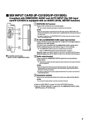
... audio monitored with a 48 kHz sampling frequency and channel range of 1 to "STATUS DISPLAY" on page 4. NOTES: • Do not touch the dip switches near the connection terminal. ● Refer to "AUTO INPUT" on page 19 for the D1 SDI signal (D1 component serial digital signal) in the stand-by mode. 4 Connection terminal Attach to "EMBEDDED AUDIO channel switch button" on page 22 for the re-locked signal. NOTES: • When the input signal...
... audio monitored with a 48 kHz sampling frequency and channel range of 1 to "STATUS DISPLAY" on page 4. NOTES: • Do not touch the dip switches near the connection terminal. ● Refer to "AUTO INPUT" on page 19 for the D1 SDI signal (D1 component serial digital signal) in the stand-by mode. 4 Connection terminal Attach to "EMBEDDED AUDIO channel switch button" on page 22 for the re-locked signal. NOTES: • When the input signal...
Instruction Manual
Page 11
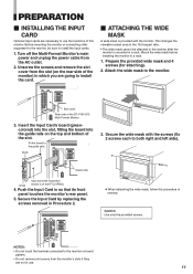
... Procedure 2. PREPARATION Ⅵ INSTALLING THE INPUT CARD Optional input cards are necessary to install the card. Ⅵ ATTACHING THE WIDE MASK A wide mask is provided with the screws (fix 2 screws each to the monitor or board pattern. • Do not remove slot covers from the monitor's slots if they are going to use . 11 Mount the wide mask before installing the monitor in so that its front panel touches the monitor's rear panel. 5. REMOTE MAKE/TRIGGER RS-485...
... Procedure 2. PREPARATION Ⅵ INSTALLING THE INPUT CARD Optional input cards are necessary to install the card. Ⅵ ATTACHING THE WIDE MASK A wide mask is provided with the screws (fix 2 screws each to the monitor or board pattern. • Do not remove slot covers from the monitor's slots if they are going to use . 11 Mount the wide mask before installing the monitor in so that its front panel touches the monitor's rear panel. 5. REMOTE MAKE/TRIGGER RS-485...
Instruction Manual
Page 12
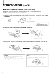
... the cover being attached to a different position. • Check to the AC power cord. a case and cover. 1. Press the cover until it clicks. 3. Caution: Use only the provided screws. Connect the AC power cord to the AC inlet, and join the Power Cord Holder cover with 2 screws (provided). 2. Attach the Power Cord Holder case to open the cover. 12 Hold until it clicks. Attach the Power Cord Holder cover to make sure the plug doesn...
... the cover being attached to a different position. • Check to the AC power cord. a case and cover. 1. Press the cover until it clicks. 3. Caution: Use only the provided screws. Connect the AC power cord to the AC inlet, and join the Power Cord Holder cover with 2 screws (provided). 2. Attach the Power Cord Holder case to open the cover. 12 Hold until it clicks. Attach the Power Cord Holder cover to make sure the plug doesn...
Instruction Manual
Page 13
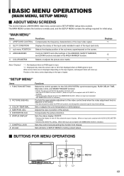
... DISPLAY 7 CONTROL LOCK 8 all items in the AREA MARKER function. 5 COLOR MATRIX Selects or adjusts the picture color matrix. Adjusts the size or position of time that the monitor has been used , and the SETUP MENU contains the settings required for initial setup. "MAIN MENU" Items Functions 1 APERTURE CONTROL Compensates the frequency characteristics of the input video signal. 2 SLOT CONDITION Displays the status of the input cards installed in each of the input card slots. 3 sub menu POSITION Selects the display position...
... DISPLAY 7 CONTROL LOCK 8 all items in the AREA MARKER function. 5 COLOR MATRIX Selects or adjusts the picture color matrix. Adjusts the size or position of time that the monitor has been used , and the SETUP MENU contains the settings required for initial setup. "MAIN MENU" Items Functions 1 APERTURE CONTROL Compensates the frequency characteristics of the input video signal. 2 SLOT CONDITION Displays the status of the input cards installed in each of the input card slots. 3 sub menu POSITION Selects the display position...
Instruction Manual
Page 14
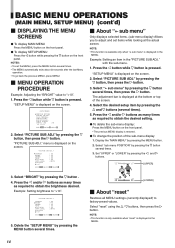
... the MENU button several times. 3. Select "reset" using the / buttons, then press the button. STATUS DISPLAY CONTROL LOCK all MENU settings (currently displayed) to "+10". menu is displayed on the screen. "SETUP MENU" is displayed on the front panel. The adjustment bar is pressed. CONTRAST BRIGHT CHROMA PHASE NTSC SETUP COMPO.LEVEL sub menu reset : 00 :+10 : 00 : 00 : 00 :SMPTE EXIT: MENU ADJUST:- + SELECT: 5. with the sub-menu. 1. Select "PICTURE SUB ADJ." Delete the "SETUP MENU" by pressing the MENU button. 2. COLOR TEMP...
... the MENU button several times. 3. Select "reset" using the / buttons, then press the button. STATUS DISPLAY CONTROL LOCK all MENU settings (currently displayed) to "+10". menu is displayed on the screen. "SETUP MENU" is displayed on the front panel. The adjustment bar is pressed. CONTRAST BRIGHT CHROMA PHASE NTSC SETUP COMPO.LEVEL sub menu reset : 00 :+10 : 00 : 00 : 00 :SMPTE EXIT: MENU ADJUST:- + SELECT: 5. with the sub-menu. 1. Select "PICTURE SUB ADJ." Delete the "SETUP MENU" by pressing the MENU button. 2. COLOR TEMP...
Instruction Manual
Page 16
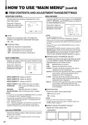
... high frequencies. For details, refer to display the setting menu illustrated on the right. SLOT CONDITION Displays the status of the input cards installed in each of the sub menu superimposed on page 14. 16 Controls ON/OFF and other settings of the input video signal. sub menu POSITION Selects the display position of the input card slots. LEVEL CONTROL FREQ. Press the button to "To change the position of the sub-menu display" on the screen. Adjusts the frequency...
... high frequencies. For details, refer to display the setting menu illustrated on the right. SLOT CONDITION Displays the status of the input cards installed in each of the sub menu superimposed on page 14. 16 Controls ON/OFF and other settings of the input video signal. sub menu POSITION Selects the display position of the input card slots. LEVEL CONTROL FREQ. Press the button to "To change the position of the sub-menu display" on the screen. Adjusts the frequency...
Instruction Manual
Page 18
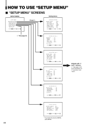
... ADJ. COLOR TEMP./BAL. STATUS DISPLAY CONTROL LOCK all reset :ON EXIT:MENU ENTER:+ SELECT: Press . HOW TO USE "SETUP MENU" Ⅵ "SETUP MENU" SCREENS SETUP MENU Setting Items FUNCTION SETTING PICTURE SUB ADJ. CONTRAST BRIGHT CHROMA PHASE NTSC SETUP COMPO.LEVEL sub menu reset : 00 : 00 : 00 : 00 : 00 : SMPTE EXIT:MENU ADJUST:- + SELECT: COLOR TEMP. : LOW BLUE DRIVE : 000 RED DRIVE : 000 GREEN CUTOFF : 000 BLUE CUTOFF : 000 RED CUTOFF : 000 sub menu reset EXIT:MENU ADJUST:- + SELECT: H.SIZE H.POSITION V.SIZE V.POSITION ZOOM H.SIZE ZOOM V.SIZE sub menu reset : 00...
... ADJ. COLOR TEMP./BAL. STATUS DISPLAY CONTROL LOCK all reset :ON EXIT:MENU ENTER:+ SELECT: Press . HOW TO USE "SETUP MENU" Ⅵ "SETUP MENU" SCREENS SETUP MENU Setting Items FUNCTION SETTING PICTURE SUB ADJ. CONTRAST BRIGHT CHROMA PHASE NTSC SETUP COMPO.LEVEL sub menu reset : 00 : 00 : 00 : 00 : 00 : SMPTE EXIT:MENU ADJUST:- + SELECT: COLOR TEMP. : LOW BLUE DRIVE : 000 RED DRIVE : 000 GREEN CUTOFF : 000 BLUE CUTOFF : 000 RED CUTOFF : 000 sub menu reset EXIT:MENU ADJUST:- + SELECT: H.SIZE H.POSITION V.SIZE V.POSITION ZOOM H.SIZE ZOOM V.SIZE sub menu reset : 00...
Instruction Manual
Page 19
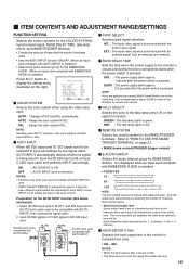
... at the same time. COLOR SYSTEM AUTO INPUT SYNC SELECT RUSH DELAY TIME TALLY SELECT REMOTE SYSTEM E.AUDIO GROUP HOUR METER X100h :AUTO :ON :INT. :STD. :GREEN :MAKE :1G :000 EXIT: MENU ADJUST:- + SELECT: Ⅵ COLOR SYSTEM Selects the color system when using the video input card. SLOW : The power supply starts approx. 3.2 seconds after the power switch is installed.) Press the button to display the setting menu illustrated on page 23. • MAKE (make contact)/TRIGGER (trigger contact...
... at the same time. COLOR SYSTEM AUTO INPUT SYNC SELECT RUSH DELAY TIME TALLY SELECT REMOTE SYSTEM E.AUDIO GROUP HOUR METER X100h :AUTO :ON :INT. :STD. :GREEN :MAKE :1G :000 EXIT: MENU ADJUST:- + SELECT: Ⅵ COLOR SYSTEM Selects the color system when using the video input card. SLOW : The power supply starts approx. 3.2 seconds after the power switch is installed.) Press the button to display the setting menu illustrated on page 23. • MAKE (make contact)/TRIGGER (trigger contact...
Instruction Manual
Page 20
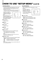
..., and change the component signal's input level settings. B00 : Compliant with M2VTR signals. LOW : Sets the color temperature to 9300. NOTE : When the RGB signal is input, only CONTRAST, BRIGHT and CHROMA are displayed. SMPTE : Compliant with Betacam 0% set -up signal. NOTE : COMPO. BLUE DRIVE RED DRIVE GREEN CUTOFF BLUE CUTOFF RED CUTOFF sub menu reset :LOW : 000 : 000 : 000 : 000 : 000 EXIT: MENU ADJUST:- + SELECT: Ⅵ COLOR TEMP. Sets or adjusts the color temperature or white balance. CONTRAST BRIGHT CHROMA...
..., and change the component signal's input level settings. B00 : Compliant with M2VTR signals. LOW : Sets the color temperature to 9300. NOTE : When the RGB signal is input, only CONTRAST, BRIGHT and CHROMA are displayed. SMPTE : Compliant with Betacam 0% set -up signal. NOTE : COMPO. BLUE DRIVE RED DRIVE GREEN CUTOFF BLUE CUTOFF RED CUTOFF sub menu reset :LOW : 000 : 000 : 000 : 000 : 000 EXIT: MENU ADJUST:- + SELECT: Ⅵ COLOR TEMP. Sets or adjusts the color temperature or white balance. CONTRAST BRIGHT CHROMA...
Instruction Manual
Page 22
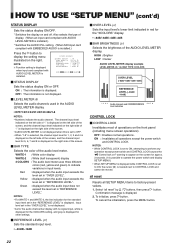
... the front panel (including menu screen operations). To initialize, press button. HOW TO USE "SETUP MENU" (cont'd) STATUS DISPLAY Sets the status display ON/OFF. * Switches the display on the right. Also selects the type of operations on the screen for the audio channel bar display with AUDIO LEVEL METER is installed.) Press the button to indicate variations in red for the standard input level set to ON, attempting to CONTROL LOCK and...
... the front panel (including menu screen operations). To initialize, press button. HOW TO USE "SETUP MENU" (cont'd) STATUS DISPLAY Sets the status display ON/OFF. * Switches the display on the right. Also selects the type of operations on the screen for the audio channel bar display with AUDIO LEVEL METER is installed.) Press the button to indicate variations in red for the standard input level set to ON, attempting to CONTROL LOCK and...
Instruction Manual
Page 25
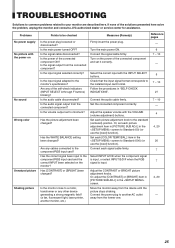
... (00) (or use the [reset] function). Set each signal cable firmly. 4 4, 20 20 7 Select INPUT A/C/E when the component signal is input, or select INPUT B/D/F when the RGB 7 signal is input. Or, adjust the [CONTRAST] or [BRIGHT] item in [PICTURE SUB ADJ.] in the screen to be checked Is the power plug loosened or disconnected? Has the picture adjustment been changed ? Has [CONTRAST] or [BRIGHT] been changed ? Connect the signal cable firmly. Adjust the speaker volume with the INPUT SELECT buttons. Or, set each [COLOR TEMP./BAL...
... (00) (or use the [reset] function). Set each signal cable firmly. 4 4, 20 20 7 Select INPUT A/C/E when the component signal is input, or select INPUT B/D/F when the RGB 7 signal is input. Or, adjust the [CONTRAST] or [BRIGHT] item in [PICTURE SUB ADJ.] in the screen to be checked Is the power plug loosened or disconnected? Has the picture adjustment been changed ? Has [CONTRAST] or [BRIGHT] been changed ? Connect the signal cable firmly. Adjust the speaker volume with the INPUT SELECT buttons. Or, set each [COLOR TEMP./BAL...
Instruction Manual
Page 26
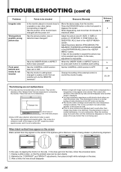
... used. Adjust the picture size (H. When the UNDER SCAN or ASPECT button is used.) The screen might appear as a result of the monitor been changed to enable control from an external unit via the REMOTE terminals? Move the monitors away from the monitor. TROUBLESHOOTING (cont'd) Problems Irregular color Wrong picture position, wrong picture size Front panel buttons and knobs do not function Points to be checked Is the monitor placed or moved close to a speaker...
... used. Adjust the picture size (H. When the UNDER SCAN or ASPECT button is used.) The screen might appear as a result of the monitor been changed to enable control from an external unit via the REMOTE terminals? Move the monitors away from the monitor. TROUBLESHOOTING (cont'd) Problems Irregular color Wrong picture position, wrong picture size Front panel buttons and knobs do not function Points to be checked Is the monitor placed or moved close to a speaker...
Instruction Manual
Page 27
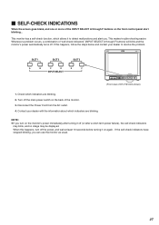
... control panel start blinking... This monitor has a self-check function, which indicators are blinking. 2. Disconnect the Power Cord from the AC outlet. 4. If this happens, turn on again. This makes trouble-shooting easier. Contact your dealer to detect malfunctions and alert you can use the monitor as usual. 27 Ⅵ SELF-CHECK INDICATIONS When the screen goes blank, and one or more of the INPUT SELECT A through F buttons) will blink...
... control panel start blinking... This monitor has a self-check function, which indicators are blinking. 2. Disconnect the Power Cord from the AC outlet. 4. If this happens, turn on again. This makes trouble-shooting easier. Contact your dealer to detect malfunctions and alert you can use the monitor as usual. 27 Ⅵ SELF-CHECK INDICATIONS When the screen goes blank, and one or more of the INPUT SELECT A through F buttons) will blink...
Instruction Manual
Page 28
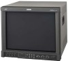
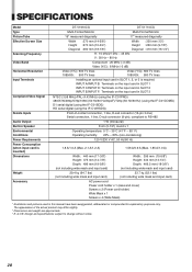
... (15-pin 3-line) Serial connection, 1 line, D-sub connector (9-pin), compliant to change without notice. 28 SPECIFICATIONS Model Type Picture Tube Effective Screen Size Scanning Frequency Video Band Horizontal Resolution Input Terminals Compliant Video Signal Remote Inputs Audio Output Built-in Speaker Environmental Conditions Power Requirements Power Consumption (when input card is inserted) Dimensions Weight Accessory DT-V1910CG DT-V1710CG Multi-Format Monitor Multi-Format Monitor 19" measured diagonally 17" measured diagonally Width :370 mm (14-5/8") Height :270 mm (10...
... (15-pin 3-line) Serial connection, 1 line, D-sub connector (9-pin), compliant to change without notice. 28 SPECIFICATIONS Model Type Picture Tube Effective Screen Size Scanning Frequency Video Band Horizontal Resolution Input Terminals Compliant Video Signal Remote Inputs Audio Output Built-in Speaker Environmental Conditions Power Requirements Power Consumption (when input card is inserted) Dimensions Weight Accessory DT-V1910CG DT-V1710CG Multi-Format Monitor Multi-Format Monitor 19" measured diagonally 17" measured diagonally Width :370 mm (14-5/8") Height :270 mm (10...

