
Product Specification
Page 4
... Processors...42 6.2.2 Memory Subsystem 45 6.2.3 PCI...51 6.2.4 PCI Express...52 6.2.5 Keyboard/Mouse...53 6.2.6 Universal Serial Bus (USB 53 6.2.7 IDE...53 6.2.8 Removable Media Drives 53 6.2.9 Flash ROM...54 6.3 BIOS POST ...54 6.3.1 User Interface ...54 6.3.2 System Diagnostic Screen 55 6.3.3 Quiet Boot / OEM Splash Screen 55 6.3.4 BIOS Boot Popup Menu 56 6.4 BIOS Setup Utility 56 6.4.1 Localization...56 6.4.2 Console Redirection 57 6.4.3 Configuration Reset 57 6.4.4 Keyboard Commands 57 6.4.5 Entering BIOS Setup 58 6.5 Security...75 6.5.1 Operating Model...
... Processors...42 6.2.2 Memory Subsystem 45 6.2.3 PCI...51 6.2.4 PCI Express...52 6.2.5 Keyboard/Mouse...53 6.2.6 Universal Serial Bus (USB 53 6.2.7 IDE...53 6.2.8 Removable Media Drives 53 6.2.9 Flash ROM...54 6.3 BIOS POST ...54 6.3.1 User Interface ...54 6.3.2 System Diagnostic Screen 55 6.3.3 Quiet Boot / OEM Splash Screen 55 6.3.4 BIOS Boot Popup Menu 56 6.4 BIOS Setup Utility 56 6.4.1 Localization...56 6.4.2 Console Redirection 57 6.4.3 Configuration Reset 57 6.4.4 Keyboard Commands 57 6.4.5 Entering BIOS Setup 58 6.5 Security...75 6.5.1 Operating Model...

Product Specification
Page 6
... Power Support 123 11.4 Power Supply Specifications 123 11.4.1 Power Timing...123 11.4.2 Voltage Recovery Timing Specifications 126 12. Server Board SE7320EP2 and SE7525RP2 Connectors 104 10.1 Main Power Connector 104 10.2 Memory Module Connector 105 10.3 Processor Socket 107 10.4 I2C Header ...110 10.5 PCI Slot Connector 111 10.6 Front Panel Connector 114 10.7 VGA Connector...115 10.8 NIC Connector ...115 10.9 IDE Connector ...116 10.10 SATA Connector 116 10.11 USB Connector...117 10.12 Floppy Connector 118 10.13 Serial Port Connector 118 10.14 Keyboard...
... Power Support 123 11.4 Power Supply Specifications 123 11.4.1 Power Timing...123 11.4.2 Voltage Recovery Timing Specifications 126 12. Server Board SE7320EP2 and SE7525RP2 Connectors 104 10.1 Main Power Connector 104 10.2 Memory Module Connector 105 10.3 Processor Socket 107 10.4 I2C Header ...110 10.5 PCI Slot Connector 111 10.6 Front Panel Connector 114 10.7 VGA Connector...115 10.8 NIC Connector ...115 10.9 IDE Connector ...116 10.10 SATA Connector 116 10.11 USB Connector...117 10.12 Floppy Connector 118 10.13 Serial Port Connector 118 10.14 Keyboard...

Product Specification
Page 9
... 43. Supported Wake Events 87 Table 50. BIOS Setup, PCI Configuration Sub-menu Selections 67 Table 34. BIOS Setup, Security Menu Options 71 Table 42. Memory BIOS Messages 95 Table 56. POST Error Messages and Handling 101 Table 65. BIOS Setup, Boot Settings Configuration Sub-menu Selections 69 Table 37. POST Code Checkpoints 90 Table 51. Miscellaneous BIOS Messages 99 Table 62. POST Error Beep Codes 103 Table 67. BIOS Setup, Boot Device Priority Sub-menu Selections 70 Table 38. BIOS Setup, Hard Disk Drive Sub-Menu Selections 70...
... 43. Supported Wake Events 87 Table 50. BIOS Setup, PCI Configuration Sub-menu Selections 67 Table 34. BIOS Setup, Security Menu Options 71 Table 42. Memory BIOS Messages 95 Table 56. POST Error Messages and Handling 101 Table 65. BIOS Setup, Boot Settings Configuration Sub-menu Selections 69 Table 37. POST Code Checkpoints 90 Table 51. Miscellaneous BIOS Messages 99 Table 62. POST Error Beep Codes 103 Table 67. BIOS Setup, Boot Device Priority Sub-menu Selections 70 Table 38. BIOS Setup, Hard Disk Drive Sub-Menu Selections 70...

Product Specification
Page 10
...-001 Power Connector Pin-out (J12 104 Table 69. Power Supply Voltage Specification 123 Table 97. List of Tables Intel® Server Board SE7320EP2 / Intel® Server Board SE7525RP2 Table 68. PCI Express Slot Pin-out (J13 for x8, J14 for x16 113 Table 78. Keyboard and Mouse PS/2 Connectors Pin-out (J2 119 Table 88. 3-pin Fan Headers Pin-out (J1, J48 119 Table 89. 4-pin Fan Headers Pin-out (J7, J44, J45, J46 119 Table 90. 6-pin Fan Headers Pin...
...-001 Power Connector Pin-out (J12 104 Table 69. Power Supply Voltage Specification 123 Table 97. List of Tables Intel® Server Board SE7320EP2 / Intel® Server Board SE7525RP2 Table 68. PCI Express Slot Pin-out (J13 for x8, J14 for x16 113 Table 78. Keyboard and Mouse PS/2 Connectors Pin-out (J2 119 Table 88. 3-pin Fan Headers Pin-out (J1, J48 119 Table 89. 4-pin Fan Headers Pin-out (J7, J44, J45, J46 119 Table 90. 6-pin Fan Headers Pin...
Product Specification
Page 23
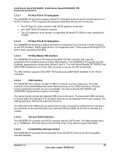
... 3.2.3.2 PCI Bus P64-B I /O panel area next to access the IDE functionality. The 6300ESB ICH supports two IDE channels, supporting two drives each (drives 0 and 1). All ports function identically and with 3D/2D graphics accelerator ƒ One Intel® 82541PI network controller ƒ Two 5V expansion slots capable of two 82C59 PIC devices for ISA-compatible interrupt handling. The USB specification defines the external connectors. The Intel Server Boards SE7320EP2 and SE7525RP2 implement one EHCI USB 2.0 controller and...
... 3.2.3.2 PCI Bus P64-B I /O panel area next to access the IDE functionality. The 6300ESB ICH supports two IDE channels, supporting two drives each (drives 0 and 1). All ports function identically and with 3D/2D graphics accelerator ƒ One Intel® 82541PI network controller ƒ Two 5V expansion slots capable of two 82C59 PIC devices for ISA-compatible interrupt handling. The USB specification defines the external connectors. The Intel Server Boards SE7320EP2 and SE7525RP2 implement one EHCI USB 2.0 controller and...
Product Specification
Page 34
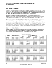
... refresh rate. Supported - - 34 Revision 1.0 Intel order number D24635-001 As an option, the video controller can be set to 1024 x 768 resolution in a 272pin PBGA. The server boards provide a standard 15-pin VGA connector at the rear of video memory. The table specifies the minimum memory requirement for both CRT and LCD monitors with Z Buffer Disabled Supported Supported Supported Supported Supported Supported Supported Supported Supported Supported Supported - The ATI Rage XL chip contains a SVGA video controller, clock generator, 2D...
... refresh rate. Supported - - 34 Revision 1.0 Intel order number D24635-001 As an option, the video controller can be set to 1024 x 768 resolution in a 272pin PBGA. The server boards provide a standard 15-pin VGA connector at the rear of video memory. The table specifies the minimum memory requirement for both CRT and LCD monitors with Z Buffer Disabled Supported Supported Supported Supported Supported Supported Supported Supported Supported Supported Supported - The ATI Rage XL chip contains a SVGA video controller, clock generator, 2D...
Product Specification
Page 43
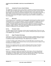
... Board SE7320EP2 / Intel® Server Board SE7525RP2 TPS BIOS 6.2.1.6 Jumperless Processor Speed Settings The Intel® Xeon™ processor does not use jumpers or switches to modify the cache configuration, size or policies. There are no value works for all installed processors, all processors. This feature changes the processor operating ratio and voltage similar to all processors not capable of speeds supported by the amount of the Intel SpeedStep® Technology. If all processors in non-volatile memory and loading...
... Board SE7320EP2 / Intel® Server Board SE7525RP2 TPS BIOS 6.2.1.6 Jumperless Processor Speed Settings The Intel® Xeon™ processor does not use jumpers or switches to modify the cache configuration, size or policies. There are no value works for all installed processors, all processors. This feature changes the processor operating ratio and voltage similar to all processors not capable of speeds supported by the amount of the Intel SpeedStep® Technology. If all processors in non-volatile memory and loading...

Product Specification
Page 46
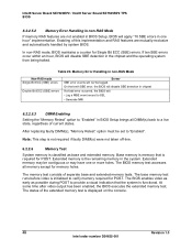
... for use by the BIOS before using BIOS Setup. Runtime DIMM status is set to step 2. 2. ECC memory initialization cannot be aborted and may be used. The memory-sizing algorithm determines the size of each installed memory module to single channel mode B. The total amount of the installed memory modules. A faulty DIMM is detected to initialize ECC. Intel® Server Board SE7320EP2 / Intel® Server Board SE7525RP2 TPS BIOS The BIOS reads the Serial Presence...
... for use by the BIOS before using BIOS Setup. Runtime DIMM status is set to step 2. 2. ECC memory initialization cannot be aborted and may be used. The memory-sizing algorithm determines the size of each installed memory module to single channel mode B. The total amount of the installed memory modules. A faulty DIMM is detected to initialize ECC. Intel® Server Board SE7320EP2 / Intel® Server Board SE7525RP2 TPS BIOS The BIOS reads the Serial Presence...
Product Specification
Page 48
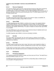
...-RAS Mode Non-RAS mode Single Bit ECC (SBE) errors Double Bit ECC (DBE) errors Server SBE error events will apply "10 SBE errors in one or more holes. After replacing faulty DIMM(s), "Memory Retest" option must be logged. The BIOS memory test accesses all DIMM(s) back to a live state, regardless of this implementation and RAS features are not enabled in BIOS Setup, BIOS will not be set to "Enabled...
...-RAS Mode Non-RAS mode Single Bit ECC (SBE) errors Double Bit ECC (DBE) errors Server SBE error events will apply "10 SBE errors in one or more holes. After replacing faulty DIMM(s), "Memory Retest" option must be logged. The BIOS memory test accesses all DIMM(s) back to a live state, regardless of this implementation and RAS features are not enabled in BIOS Setup, BIOS will not be set to "Enabled...
Product Specification
Page 52
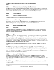
... functions as defined in the PCI BIOS Specification. Dual video mode is disabled by the console redirection binary (if enabled) and the user binary (if present and configured for devices. 6.2.3.4 Option ROMs The BIOS dispatches the option ROMs to PCI Express devices. 52 Revision 1.0 Intel order number D24635-001 The BIOS trains the link during boot and checks the corresponding status to disable any port not connected to available memory space in the standard address range...
... functions as defined in the PCI BIOS Specification. Dual video mode is disabled by the console redirection binary (if enabled) and the user binary (if present and configured for devices. 6.2.3.4 Option ROMs The BIOS dispatches the option ROMs to PCI Express devices. 52 Revision 1.0 Intel order number D24635-001 The BIOS trains the link during boot and checks the corresponding status to disable any port not connected to available memory space in the standard address range...
Product Specification
Page 53
...-ROM drive or DVD drive (read /write services that are connected to these controllers. Revision 1.0 53 Intel order number D24635-001 Intel® Server Board SE7320EP2 / Intel® Server Board SE7525RP2 TPS BIOS 6.2.4.2 PCI Express Enhanced Configuration Mechanisms PCI Express extends the configuration space to 4096 bytes per device/function as the PATA controllers. The PCI Express configuration space is not supported by the PCI 2.3 configuration space. From a software standpoint, SATA controllers present the same register interface as compared to the USB 1.1 specification...
...-ROM drive or DVD drive (read /write services that are connected to these controllers. Revision 1.0 53 Intel order number D24635-001 Intel® Server Board SE7320EP2 / Intel® Server Board SE7525RP2 TPS BIOS 6.2.4.2 PCI Express Enhanced Configuration Mechanisms PCI Express extends the configuration space to 4096 bytes per device/function as the PATA controllers. The PCI Express configuration space is not supported by the PCI 2.3 configuration space. From a software standpoint, SATA controllers present the same register interface as compared to the USB 1.1 specification...

Product Specification
Page 75
... supported by "trial and error." 6.5.1 Operating Model The following table summarizes the operation of the drive C: if it difficult to the server is not in BIOS setup. Once set, a password can be cleared by setup options. The Administrator has control over all fields in the BIOS setup Security menu controls the user access level. The BIOS uses passwords to Normal in or keyboard input is determined by entering the password change any setup features. Once secure mode...
... supported by "trial and error." 6.5.1 Operating Model The following table summarizes the operation of the drive C: if it difficult to the server is not in BIOS setup. Once set, a password can be cleared by setup options. The Administrator has control over all fields in the BIOS setup Security menu controls the user access level. The BIOS uses passwords to Normal in or keyboard input is determined by entering the password change any setup features. Once secure mode...

Product Specification
Page 76
... Is User Password Is Login Type: Admin Installed Installed Set Admin Password (visible) Set User Password (visible) User Access Level [(show current status of user access level)] (visible) Clear User Password (visible) Login Type: User Set Admin Password (shaded) Set User Password (visible) User Access Level [(show current status of user access level)] (shaded) Clear User Password (shaded) 76 Revision 1.0 Intel order number D24635-001 Intel® Server Board SE7320EP2 / Intel® Server Board SE7525RP2 TPS BIOS 6.5.2 Notes: Administrator/User Passwords and F2 Setup Usage Model...
... Is User Password Is Login Type: Admin Installed Installed Set Admin Password (visible) Set User Password (visible) User Access Level [(show current status of user access level)] (visible) Clear User Password (visible) Login Type: User Set Admin Password (shaded) Set User Password (visible) User Access Level [(show current status of user access level)] (shaded) Clear User Password (shaded) 76 Revision 1.0 Intel order number D24635-001 Intel® Server Board SE7320EP2 / Intel® Server Board SE7525RP2 TPS BIOS 6.5.2 Notes: Administrator/User Passwords and F2 Setup Usage Model...
Product Specification
Page 88
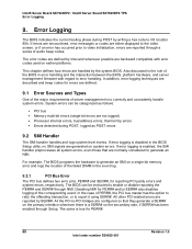
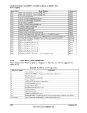
... audio beep codes. In addition, error-logging techniques are described and beep codes for errors are normally considered to error handling. All other PCI-related errors are not logged) ƒ Processor internal errors, bus/address errors, thermal trip errors ƒ Errors detected during POST by SERR#. Error Logging The BIOS indicates the current testing phase during POST, logged as follows: ƒ PCI bus ƒ Memory multi-bit errors (single-bit errors are reported by writing a hex code to enable or disable...
... audio beep codes. In addition, error-logging techniques are described and beep codes for errors are normally considered to error handling. All other PCI-related errors are not logged) ƒ Processor internal errors, bus/address errors, thermal trip errors ƒ Errors detected during POST by SERR#. Error Logging The BIOS indicates the current testing phase during POST, logged as follows: ƒ PCI bus ƒ Memory multi-bit errors (single-bit errors are reported by writing a hex code to enable or disable...

Product Specification
Page 91
.... Displays the system configuration screen if enabled. Detect different devices (Parallel ports, serial ports, and coprocessor in the system and update the BDA, EBDA...etc. etc.) successfully installed in CPU, ... Allocates memory for Extended BIOS Data Area from memory found in F000h segment with this value may be different from one platform to the user and gets the user response for error. Log errors encountered during POST. Clean-up work...
.... Displays the system configuration screen if enabled. Detect different devices (Parallel ports, serial ports, and coprocessor in the system and update the BDA, EBDA...etc. etc.) successfully installed in CPU, ... Allocates memory for Extended BIOS Data Area from memory found in F000h segment with this value may be different from one platform to the user and gets the user response for error. Log errors encountered during POST. Clean-up work...

Product Specification
Page 98
... resources (Memory or I/O). capable hard disk sends this case, the BIOS must be reported by an ATAPI device using the S.M.A.R.T. A S.M.A.R.T. failure messages may indicate the need to appear when a brand new CPU is trying to replace the hard disk. VIRUS: Continue (Y/N)? If the BIOS detects possible virus activity, it will only be displayed if Virus Detection is enabled in POST. This is a fatal error, often indication a problem with...
... resources (Memory or I/O). capable hard disk sends this case, the BIOS must be reported by an ATAPI device using the S.M.A.R.T. A S.M.A.R.T. failure messages may indicate the need to appear when a brand new CPU is trying to replace the hard disk. VIRUS: Continue (Y/N)? If the BIOS detects possible virus activity, it will only be displayed if Virus Detection is enabled in POST. This is a fatal error, often indication a problem with...
Product Specification
Page 102
... missing memory in slot 1A Bad or missing memory in slot 3B Bad or missing memory in slot 2B Bad or missing memory in the BIOS. Force all memory back online. CPUID, Processor Model are they logged in the following table do not appear on the video, nor are different Processor speeds mismatched CMOS Cleared By Jumper Password cleared by this USB Host Controller !!! Intel® Server Board SE7320EP2 / Intel® Server Board SE7525RP2 TPS Error Logging Error Code...
... missing memory in slot 1A Bad or missing memory in slot 3B Bad or missing memory in slot 2B Bad or missing memory in the BIOS. Force all memory back online. CPUID, Processor Model are they logged in the following table do not appear on the video, nor are different Processor speeds mismatched CMOS Cleared By Jumper Password cleared by this USB Host Controller !!! Intel® Server Board SE7320EP2 / Intel® Server Board SE7525RP2 TPS Error Logging Error Code...
Product Specification
Page 120
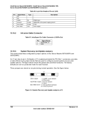
... the Server Boards SE7320EP2 and SE7525RP2. IntruSuper IOn Cable Connector (J19)Pin-Out Pin Signal Name 1 INTRUDER_N 2 GND 10.15.3 System Recovery and Update Jumpers This section describes configuration jumper options on six pins during normal operation. System Recovery and Update Jumpers (J17) 120 Revision 1.0 Intel order number D24635-001 An 11-pin (key in pin 4, 8) Header (J17), located just beside the PCI Slot 1 connectors, provides a total of three 3-pin jumper blocks that are used to a protected mode for...
... the Server Boards SE7320EP2 and SE7525RP2. IntruSuper IOn Cable Connector (J19)Pin-Out Pin Signal Name 1 INTRUDER_N 2 GND 10.15.3 System Recovery and Update Jumpers This section describes configuration jumper options on six pins during normal operation. System Recovery and Update Jumpers (J17) 120 Revision 1.0 Intel order number D24635-001 An 11-pin (key in pin 4, 8) Header (J17), located just beside the PCI Slot 1 connectors, provides a total of three 3-pin jumper blocks that are used to a protected mode for...
Product Specification
Page 131
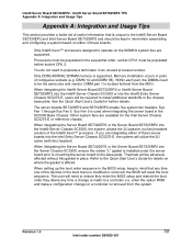
... Intel Entry Server Chassis SC5275-E, the system will utilize the 2U active (with fan) heatsink. Other system fans are supported. Refer to install additional standoffs in mind while assembling and configuring a system based on where the gasket is made to the Intel® Server Board SE7320EP2 and Intel Server Board SE7525RP2 and should be populated before socket CPU 2. You do not need to ensure they enter the BIOS setup...
... Intel Entry Server Chassis SC5275-E, the system will utilize the 2U active (with fan) heatsink. Other system fans are supported. Refer to install additional standoffs in mind while assembling and configuring a system based on where the gasket is made to the Intel® Server Board SE7320EP2 and Intel Server Board SE7525RP2 and should be populated before socket CPU 2. You do not need to ensure they enter the BIOS setup...
Quick Start Guide
Page 1
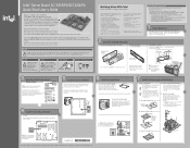
... the gasket to configure the BIOS fan control. If installing this step if you are included with the Server Board SE7525RP2, a minimum 600W power supply is your chassis for the appropriate location(s). Nella. Standoff numbering varies by taking advantage of the outstanding value Intel provides to enable e-Business • Intel® Server Management • Comprehensive training services • Worldwide 24x7 technical support [AT&T Country Code + 866-655...
... the gasket to configure the BIOS fan control. If installing this step if you are included with the Server Board SE7525RP2, a minimum 600W power supply is your chassis for the appropriate location(s). Nella. Standoff numbering varies by taking advantage of the outstanding value Intel provides to enable e-Business • Intel® Server Management • Comprehensive training services • Worldwide 24x7 technical support [AT&T Country Code + 866-655...


