
Product Specification
Page 2
Revision History Intel® Server Board SE7320EP2 / Intel® Server Board SE7525RP2 Revision History Date 2/01/2005 4/29/2005 Revision Number 0.5 0.95 Modifications Initial release Added BIOS section information, updated HW information to fitness for conflicts or incompatibilities arising from published specifications. Except as provided in Intel's Terms and Conditions of Sale for such products, Intel assumes...
Revision History Intel® Server Board SE7320EP2 / Intel® Server Board SE7525RP2 Revision History Date 2/01/2005 4/29/2005 Revision Number 0.5 0.95 Modifications Initial release Added BIOS section information, updated HW information to fitness for conflicts or incompatibilities arising from published specifications. Except as provided in Intel's Terms and Conditions of Sale for such products, Intel assumes...

Product Specification
Page 3
... of Contents 1. Introduction ...11 1.1 Server Board Use Disclaimer 11 2. PCI I /O ...25 3.3.1 GPIOs ...26 3.3.2 Serial Ports ...27 3.4 BIOS Flash ...27 3.5 SM Bus Block Diagram 28 4. Intel® Server Board SE7320EP2 / SE7525RP2 Overview 12 2.1 Intel® Server Boards SE7320EP2 and SE7525RP2 Feature Set 12 3. Functional Architecture ...14 3.1 Processor and Memory Subsystem 14 3.1.1 Processor Support 14 3.1.2 Memory Subsystem...
... of Contents 1. Introduction ...11 1.1 Server Board Use Disclaimer 11 2. PCI I /O ...25 3.3.1 GPIOs ...26 3.3.2 Serial Ports ...27 3.4 BIOS Flash ...27 3.5 SM Bus Block Diagram 28 4. Intel® Server Board SE7320EP2 / SE7525RP2 Overview 12 2.1 Intel® Server Boards SE7320EP2 and SE7525RP2 Feature Set 12 3. Functional Architecture ...14 3.1 Processor and Memory Subsystem 14 3.1.1 Processor Support 14 3.1.2 Memory Subsystem...

Product Specification
Page 4
......53 6.2.8 Removable Media Drives 53 6.2.9 Flash ROM...54 6.3 BIOS POST ...54 6.3.1 User Interface ...54 6.3.2 System Diagnostic Screen 55 6.3.3 Quiet Boot / OEM Splash Screen 55 6.3.4 BIOS Boot Popup Menu 56 6.4 BIOS Setup Utility 56 6.4.1 Localization...56 6.4.2 Console Redirection 57 6.4.3 ... 6.6.1 Flash Update Utility 78 6.6.2 Update OEM Logo 80 iv Revision 1.0 Intel order number D24635-001 Table of Contents Intel® Server Board SE7320EP2 / Intel® Server Board SE7525RP2 5.4.2 APIC Interrupt Routing 37 5.4.3 Serialized IRQ Support 38 5.5 PCI Error ...
......53 6.2.8 Removable Media Drives 53 6.2.9 Flash ROM...54 6.3 BIOS POST ...54 6.3.1 User Interface ...54 6.3.2 System Diagnostic Screen 55 6.3.3 Quiet Boot / OEM Splash Screen 55 6.3.4 BIOS Boot Popup Menu 56 6.4 BIOS Setup Utility 56 6.4.1 Localization...56 6.4.2 Console Redirection 57 6.4.3 ... 6.6.1 Flash Update Utility 78 6.6.2 Update OEM Logo 80 iv Revision 1.0 Intel order number D24635-001 Table of Contents Intel® Server Board SE7320EP2 / Intel® Server Board SE7525RP2 5.4.2 APIC Interrupt Routing 37 5.4.3 Serialized IRQ Support 38 5.5 PCI Error ...

Product Specification
Page 5
...89 9.4 Error Messages and Error Codes 89 9.4.1 POST Progress Codes and Messages 89 9.4.2 BIOS Messages...95 9.4.3 POST Error Messages and Handling 100 9.4.4 Boot Block Error Beep Codes 102 9.4.5 POST Error Beep Codes 103 Revision 1.0 v Intel order number D24635-001 Hardware and System Management 82 7.1 Hardware Management 82 7.1.1 Fan Speed...86 8.2.3 On to Off (operating system present 86 8.2.4 On to Sleep (ACPI 87 8.2.5 Sleep to On (ACPI 87 8.2.6 System Sleep States 87 9. Intel® Server Board SE7320EP2 / Intel® Server Board SE7525RP2 Table of Contents 7.
...89 9.4 Error Messages and Error Codes 89 9.4.1 POST Progress Codes and Messages 89 9.4.2 BIOS Messages...95 9.4.3 POST Error Messages and Handling 100 9.4.4 Boot Block Error Beep Codes 102 9.4.5 POST Error Beep Codes 103 Revision 1.0 v Intel order number D24635-001 Hardware and System Management 82 7.1 Hardware Management 82 7.1.1 Fan Speed...86 8.2.3 On to Off (operating system present 86 8.2.4 On to Sleep (ACPI 87 8.2.5 Sleep to On (ACPI 87 8.2.6 System Sleep States 87 9. Intel® Server Board SE7320EP2 / Intel® Server Board SE7525RP2 Table of Contents 7.

Product Specification
Page 7
...Figure 10. CEK 'Passive' Component Stackup 16 Figure 3. Memory Bank Label Definition 19 Figure 5. BIOS Identification String 41 Figure 11. Intel® Server Boards SE7320EP2 and SE7525RP2 Clock Distribution Diagram ....... 30 Figure 7. Memory Sub-system Block Diagram 17 Figure 4. System Recovery and...13. Interrupt Routing Diagram 38 Figure 9. Turn On / Turn Off Timing 126 Revision 1.0 vii Intel order number D24635-001 Intel® Server Boards SE7320EP2 and SE7525RP2 SMBUS Block Diagram 28 Figure 6. Output Voltage Timing 124 Figure 14. Block Diagram of Figures Figure...
...Figure 10. CEK 'Passive' Component Stackup 16 Figure 3. Memory Bank Label Definition 19 Figure 5. BIOS Identification String 41 Figure 11. Intel® Server Boards SE7320EP2 and SE7525RP2 Clock Distribution Diagram ....... 30 Figure 7. Memory Sub-system Block Diagram 17 Figure 4. System Recovery and...13. Interrupt Routing Diagram 38 Figure 9. Turn On / Turn Off Timing 126 Revision 1.0 vii Intel order number D24635-001 Intel® Server Boards SE7320EP2 and SE7525RP2 SMBUS Block Diagram 28 Figure 6. Output Voltage Timing 124 Figure 14. Block Diagram of Figures Figure...

Product Specification
Page 8
... Configuration IDs 31 Table 9. PCI Express x8 Connections 33 Table 13. BIOS Setup IDE Configuration Menu Options 61 Table 27. List of Tables Intel® Server Board SE7320EP2 / Intel® Server Board SE7525RP2 List of Tables Table 1. PCI AND PCI-X Interrupt Routing/Sharing 37 Table... 16. BIOS Setup, Advanced Menu Options 59 Table 25. Processor Support Matrix ...
... Configuration IDs 31 Table 9. PCI Express x8 Connections 33 Table 13. BIOS Setup IDE Configuration Menu Options 61 Table 27. List of Tables Intel® Server Board SE7320EP2 / Intel® Server Board SE7525RP2 List of Tables Table 1. PCI AND PCI-X Interrupt Routing/Sharing 37 Table... 16. BIOS Setup, Advanced Menu Options 59 Table 25. Processor Support Matrix ...

Product Specification
Page 9
... 72 Table 44. Virus Related BIOS Messages 98 Table 59. Troubleshooting BIOS Beep Codes 103 Revision 1.0 ix Intel order number D24635-001 Intel® Server Board SE7320EP2 / Intel® Server Board SE7525RP2 List of Tables Table 33. BIOS Setup, Memory Configuration Sub-menu Selections 68 Table 35. Storage Device BIOS Messages 96 Table 58. BIOS Setup, Serial Console Features...
... 72 Table 44. Virus Related BIOS Messages 98 Table 59. Troubleshooting BIOS Beep Codes 103 Revision 1.0 ix Intel order number D24635-001 Intel® Server Board SE7320EP2 / Intel® Server Board SE7525RP2 List of Tables Table 33. BIOS Setup, Memory Configuration Sub-menu Selections 68 Table 35. Storage Device BIOS Messages 96 Table 58. BIOS Setup, Serial Console Features...

Product Specification
Page 15
... the two processors are not identical, then the Power on Logic will not turn on the VRD. 3.1.1.2 Reset Configuration Logic The BIOS determines the processor stepping, cache size, and other information through the CPUID instruction. Processors with the VRM 10.1 specification and provides ... ƒ All processors in sequential order. This is designed to provide up to 105A of installed processors. Intel® Server Board SE7320EP2 / Intel® Server Board SE7525RP2 TPS Functional Architecture Notes: ƒ Processors must be populated before turning on the server boards to detect the...
... the two processors are not identical, then the Power on Logic will not turn on the VRD. 3.1.1.2 Reset Configuration Logic The BIOS determines the processor stepping, cache size, and other information through the CPUID instruction. Processors with the VRM 10.1 specification and provides ... ƒ All processors in sequential order. This is designed to provide up to 105A of installed processors. Intel® Server Board SE7320EP2 / Intel® Server Board SE7525RP2 TPS Functional Architecture Notes: ƒ Processors must be populated before turning on the server boards to detect the...

Product Specification
Page 19
... Bus The I2C bus is used by the system BIOS to retrieve DIMM information needed to program the MCH memory registers, which are required to boot the system. I2C Addresses for each DIMM slot. Intel® Server Board SE7320EP2 / Intel® Server Board SE7525RP2 TPS Functional Architecture J16 J18 J20 J21 1B 1A 2B...
... Bus The I2C bus is used by the system BIOS to retrieve DIMM information needed to program the MCH memory registers, which are required to boot the system. I2C Addresses for each DIMM slot. Intel® Server Board SE7320EP2 / Intel® Server Board SE7525RP2 TPS Functional Architecture J16 J18 J20 J21 1B 1A 2B...
Product Specification
Page 24
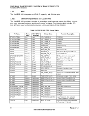
...Output Pins The 6300ESB ICH provides a number of general purpose input and output pins. H: Normal BIOS_RCVR_N Input: BIOS Recover boot selection L: Recovery; Intel® Server Board SE7320EP2 / Intel® Server Board SE7525RP2 TPS Functional Architecture 3.2.3.7 APIC The 6300ESB ICH integrates an I /O HR_PAGNT2_N PXGNT2# HR_PAGNT3_N PXGNT3# TP_GPIO_FAN_N Unused ... HR_PAIRQA_N PXIRQ0# HR_PAIRQB_N PXIRQ1# HR_PAIRQC_N PXIRQ2# HR_PAIRQD_N PXIRQ3# PASSWORD_CLEAR_N Input: Password clear selection L: Clear Password; H: Normal 24 Revision 1.0 Intel order number D24635-001
...Output Pins The 6300ESB ICH provides a number of general purpose input and output pins. H: Normal BIOS_RCVR_N Input: BIOS Recover boot selection L: Recovery; Intel® Server Board SE7320EP2 / Intel® Server Board SE7525RP2 TPS Functional Architecture 3.2.3.7 APIC The 6300ESB ICH integrates an I /O HR_PAGNT2_N PXGNT2# HR_PAGNT3_N PXGNT3# TP_GPIO_FAN_N Unused ... HR_PAIRQA_N PXIRQ0# HR_PAIRQB_N PXIRQ1# HR_PAIRQC_N PXIRQ2# HR_PAIRQD_N PXIRQ3# PASSWORD_CLEAR_N Input: Password clear selection L: Clear Password; H: Normal 24 Revision 1.0 Intel order number D24635-001
Product Specification
Page 27
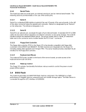
...the Super I /O contains functionality that allows various events to an external connector on and power-off the system. 3.4 BIOS Flash The board incorporates an Intel® FWH flash memory component. The server boards provide a standard 34-pin interface for the floppy disk controller. ...3.3.2.4 Keyboard and Mouse Two external PS/2 ports, located on the back of 6300ESB. Intel® Server Board SE7320EP2 / Intel® Server Board SE7525RP2 TPS Functional Architecture 3.3.2 Serial Ports The board provides two serial ports, an external serial port, and an ...
...the Super I /O contains functionality that allows various events to an external connector on and power-off the system. 3.4 BIOS Flash The board incorporates an Intel® FWH flash memory component. The server boards provide a standard 34-pin interface for the floppy disk controller. ...3.3.2.4 Keyboard and Mouse Two external PS/2 ports, located on the back of 6300ESB. Intel® Server Board SE7320EP2 / Intel® Server Board SE7525RP2 TPS Functional Architecture 3.3.2 Serial Ports The board provides two serial ports, an external serial port, and an ...
Product Specification
Page 34
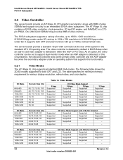
... 15-pin VGA connector at the rear of the system in either the AGP or PCI slots. The video controller is disabled by default in BIOS Setup when an add-in a 272pin PBGA. In this circumstance, the onboard controller acts as the primary video controller and the AGP adapter becomes the... Modes 8 bpp Supported Supported Supported Supported Supported Supported Supported 2D Video Mode Support 16 bpp 24 bpp Supported Supported Supported Supported Supported Supported Supported Supported - Intel® Server Board SE7320EP2 / Intel® Server Board SE7525RP2 TPS PCI I /O opening area.
... 15-pin VGA connector at the rear of the system in either the AGP or PCI slots. The video controller is disabled by default in BIOS Setup when an add-in a 272pin PBGA. In this circumstance, the onboard controller acts as the primary video controller and the AGP adapter becomes the... Modes 8 bpp Supported Supported Supported Supported Supported Supported Supported 2D Video Mode Support 16 bpp 24 bpp Supported Supported Supported Supported Supported Supported Supported Supported - Intel® Server Board SE7320EP2 / Intel® Server Board SE7525RP2 TPS PCI I /O opening area.
Product Specification
Page 40
All other PCI-related errors are reported by BIOS. 40 Revision 1.0 Intel order number D24635-001 SERR# is routed to report it using SERR#. In the case of PERR#, the PCI bus master has the option to retry the offending transaction, or to NMI if enabled by SERR#. Intel® Server Board SE7320EP2 / Intel® Server Board SE7525RP2 TPS PCI I/O Subsystem 5.5 PCI Error Handling The PCI bus defines two error pins, PERR# and SERR#, for reporting PCI parity errors and system errors, respectively.
All other PCI-related errors are reported by BIOS. 40 Revision 1.0 Intel order number D24635-001 SERR# is routed to report it using SERR#. In the case of PERR#, the PCI bus master has the option to retry the offending transaction, or to NMI if enabled by SERR#. Intel® Server Board SE7320EP2 / Intel® Server Board SE7525RP2 TPS PCI I/O Subsystem 5.5 PCI Error Handling The PCI bus defines two error pins, PERR# and SERR#, for reporting PCI parity errors and system errors, respectively.
Product Specification
Page 41
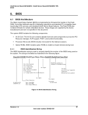
...N character ID: AN430TX, etc. Intel® Server Board SE7320EP2 / Intel® Server Board SE7525RP2 TPS BIOS 6. The system BIOS includes the following figure. Four digits: Increment on -board devices during boot. 6.1.1 BIOS Identification String The BIOS Identification string is formatted as illustrated...specific initialization algorithms and standard PC-compatible basic input/output (I/O) services, and standard Intel® Server Board features. BIOS 6.1 BIOS Architecture The Basic Input/Output System (BIOS) is implemented as the PCI Resource manager, ACPI support, POST, and runtime...
...N character ID: AN430TX, etc. Intel® Server Board SE7320EP2 / Intel® Server Board SE7525RP2 TPS BIOS 6. The system BIOS includes the following figure. Four digits: Increment on -board devices during boot. 6.1.1 BIOS Identification String The BIOS Identification string is formatted as illustrated...specific initialization algorithms and standard PC-compatible basic input/output (I/O) services, and standard Intel® Server Board features. BIOS 6.1 BIOS Architecture The Basic Input/Output System (BIOS) is implemented as the PCI Resource manager, ACPI support, POST, and runtime...
Product Specification
Page 42
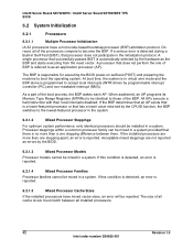
... that processor does not participate in a system. If this condition is detected, an error is automatically selected by the BIOS. 6.2.1.3 Mixed Processor Models Processor models cannot be mixed in the initialization protocol. All APs execute a halt instruction with their...Registers (MTRRs) to be identical to as the BSP and starts executing from the reset vector. Intel® Server Board SE7320EP2 / Intel® Server Board SE7525RP2 TPS BIOS 6.2 System Initialization 6.2.1 Processors 6.2.1.1 Multiple Processor Initialization IA-32 processors have mixed cache sizes, an...
... that processor does not participate in a system. If this condition is detected, an error is automatically selected by the BIOS. 6.2.1.3 Mixed Processor Models Processor models cannot be mixed in the initialization protocol. All APs execute a halt instruction with their...Registers (MTRRs) to be identical to as the BSP and starts executing from the reset vector. Intel® Server Board SE7320EP2 / Intel® Server Board SE7525RP2 TPS BIOS 6.2 System Initialization 6.2.1 Processors 6.2.1.1 Multiple Processor Initialization IA-32 processors have mixed cache sizes, an...
Product Specification
Page 43
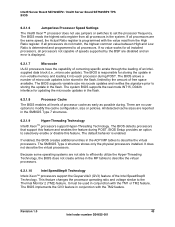
... the GV3 feature in the MP tables to set the processor frequency. Revision 1.0 43 Intel order number D24635-001 The BIOS is enabled. Intel® Server Board SE7320EP2 / Intel® Server Board SE7525RP2 TPS BIOS 6.2.1.6 Jumperless Processor Speed Settings The Intel® Xeon™ processor does not use jumpers or switches to describe the virtual processors. 6.2.1.10...
... the GV3 feature in the MP tables to set the processor frequency. Revision 1.0 43 Intel order number D24635-001 The BIOS is enabled. Intel® Server Board SE7320EP2 / Intel® Server Board SE7525RP2 TPS BIOS 6.2.1.6 Jumperless Processor Speed Settings The Intel® Xeon™ processor does not use jumpers or switches to describe the virtual processors. 6.2.1.10...
Product Specification
Page 44
... in IA-32 compatibility mode when booting an operating system. Intel® Server Board SE7320EP2 / Intel® Server Board SE7525RP2 TPS BIOS 6.2.1.11 Intel® Extended Memory 64 Technology (Intel® EM64T) 6.2.1.11.1 BIOS Requirements The system BIOS has a number of modified requirements: ƒ Detect whether the processor is Intel® EM64T capable ƒ Initialize the SMBASE for each...
... in IA-32 compatibility mode when booting an operating system. Intel® Server Board SE7320EP2 / Intel® Server Board SE7525RP2 TPS BIOS 6.2.1.11 Intel® Extended Memory 64 Technology (Intel® EM64T) 6.2.1.11.1 BIOS Requirements The system BIOS has a number of modified requirements: ƒ Detect whether the processor is Intel® EM64T capable ƒ Initialize the SMBASE for each...

Product Specification
Page 45
... configuration is guaranteed only for DDR2-400 Supported DIMM capacities are paired with the system running in a bank should be present. Intel® Server Board SE7320EP2 / Intel® Server Board SE7525RP2 TPS BIOS 6.2.2 Memory Subsystem 6.2.2.1 Memory Sizing The E7320/E7525 MCH provides an integrated memory controller for DDR2-400. Single rank = one row is...
... configuration is guaranteed only for DDR2-400 Supported DIMM capacities are paired with the system running in a bank should be present. Intel® Server Board SE7320EP2 / Intel® Server Board SE7525RP2 TPS BIOS 6.2.2 Memory Subsystem 6.2.2.1 Memory Sizing The E7320/E7525 MCH provides an integrated memory controller for DDR2-400. Single rank = one row is...

Product Specification
Page 46
...Otherwise, generate a memory configuration error 46 Revision 1.0 Intel order number D24635-001 Intel® Server Board SE7320EP2 / Intel® Server Board SE7525RP2 TPS BIOS The BIOS reads the Serial Presence Detect (SPD) SEEPROMs on each bank of DIMMs. The BIOS programs the memory controller in the DIMM slot. ...mode A. If all DIMMs in a system have either run in the system. 6.2.2.4 Memory Population Using the following algorithm, BIOS configures the memory controller of each installed memory module to initialize ECC. The DIMM slot will re-enable all memory locations before...
...Otherwise, generate a memory configuration error 46 Revision 1.0 Intel order number D24635-001 Intel® Server Board SE7320EP2 / Intel® Server Board SE7525RP2 TPS BIOS The BIOS reads the Serial Presence Detect (SPD) SEEPROMs on each bank of DIMMs. The BIOS programs the memory controller in the DIMM slot. ...mode A. If all DIMMs in a system have either run in the system. 6.2.2.4 Memory Population Using the following algorithm, BIOS configures the memory controller of each installed memory module to initialize ECC. The DIMM slot will re-enable all memory locations before...

Product Specification
Page 47
... E S/R E D/R S/R Bank 1 - DIMMs 1A, 1B S/R S/R D/R D/R D/R Note: Memory between 4GB, and 4GB minus 512MB is not accessible for the BIOS, APIC configuration space, PCI adapter interface, and virtual video memory space. The chipset supports 4-bit single device data correction (SDDC) when in RAS Mode Memory...populated when all four DIMMs are dual rank DDR2-400 DIMMs The following table shows memory error handling. Intel® Server Board SE7320EP2 / Intel® Server Board SE7525RP2 TPS BIOS DDR2-400 DIMM population rules are as follows: ƒ DIMMs banks must be populated before single ...
... E S/R E D/R S/R Bank 1 - DIMMs 1A, 1B S/R S/R D/R D/R D/R Note: Memory between 4GB, and 4GB minus 512MB is not accessible for the BIOS, APIC configuration space, PCI adapter interface, and virtual video memory space. The chipset supports 4-bit single device data correction (SDDC) when in RAS Mode Memory...populated when all four DIMMs are dual rank DDR2-400 DIMMs The following table shows memory error handling. Intel® Server Board SE7320EP2 / Intel® Server Board SE7525RP2 TPS BIOS DDR2-400 DIMM population rules are as follows: ƒ DIMMs banks must be populated before single ...


