
User Guide
Page 3
... locations. Use this chapter for step-bystep instructions and diagrams for installing or replacing components such as the memory, processor, and the battery, among other components you will also find suggestions for troubleshooting, upgrading, and repairing this manual, refer to update the system. Chapter 4 provides troubleshooting information. In this manual show product code SE7520BD2. This manual is available in this chapter, you may be required to http://support.intel.com/support/motherboards...
... locations. Use this chapter for step-bystep instructions and diagrams for installing or replacing components such as the memory, processor, and the battery, among other components you will also find suggestions for troubleshooting, upgrading, and repairing this manual, refer to update the system. Chapter 4 provides troubleshooting information. In this manual show product code SE7520BD2. This manual is available in this chapter, you may be required to http://support.intel.com/support/motherboards...
User Guide
Page 5
... final configuration of your end system product may require additional EMC compliance testing. Preface Processors that have been tested with this product DIMMs that have been tested with this product To make sure your system falls within the allowed power budget For software to manage your Intel® Server For firmware, BIOS updates, and drivers Supported Processor List Tested Memory List Power Budget Tool Intel®...
... final configuration of your end system product may require additional EMC compliance testing. Preface Processors that have been tested with this product DIMMs that have been tested with this product To make sure your system falls within the allowed power budget For software to manage your Intel® Server For firmware, BIOS updates, and drivers Supported Processor List Tested Memory List Power Budget Tool Intel®...
User Guide
Page 9
... 20 Configuration Jumpers ...22 Back Panel Connectors...23 Hardware Requirements ...24 Server Chassis ...24 Processor ...24 Memory ...25 2 Hardware Installations and Upgrades 28 Before You Begin ...28 Tools and Supplies Needed 28 Installing and Removing Memory 28 Installing DIMMs...29 Removing DIMMs...30 Installing or Replacing the Processor 30 Installing the Processor 31 Removing a Processor 34 Installing or Removing a PCI Card 34 Replacing the Backup Battery 35 3 Server Utilities 37 Using the BIOS Setup Utility 37 Starting Setup ...37 If You Cannot Access Setup 37 Setup Menus...
... 20 Configuration Jumpers ...22 Back Panel Connectors...23 Hardware Requirements ...24 Server Chassis ...24 Processor ...24 Memory ...25 2 Hardware Installations and Upgrades 28 Before You Begin ...28 Tools and Supplies Needed 28 Installing and Removing Memory 28 Installing DIMMs...29 Removing DIMMs...30 Installing or Replacing the Processor 30 Installing the Processor 31 Removing a Processor 34 Installing or Removing a PCI Card 34 Replacing the Backup Battery 35 3 Server Utilities 37 Using the BIOS Setup Utility 37 Starting Setup ...37 If You Cannot Access Setup 37 Setup Menus...
User Guide
Page 11
... LEDs ...23 Table 5. POST Error Beep Codes 54 Table 9. Configuration Jumper Location 22 Figure 5. Back Panel Connectors 23 Figure 6. Closing Socket Lever 32 Figure 10. Server Board Varieties 14 Table 2. Boot Block Error Beep Codes 54 Table 8. BIOS Beep Codes...55 Table 10. Product Certification Markings 57 xi Contents Figures Figure 1. Intel® Server Board SE7520BD2 13 Figure 2. Server Board Features 17 Table 3. Opening Socket Lever 31 Figure 8. Inserting Processor...31 Figure 9. Intel® Server Chassis Supported...
... LEDs ...23 Table 5. POST Error Beep Codes 54 Table 9. Configuration Jumper Location 22 Figure 5. Back Panel Connectors 23 Figure 6. Closing Socket Lever 32 Figure 10. Server Board Varieties 14 Table 2. Boot Block Error Beep Codes 54 Table 8. BIOS Beep Codes...55 Table 10. Product Certification Markings 57 xi Contents Figures Figure 1. Intel® Server Board SE7520BD2 13 Figure 2. Server Board Features 17 Table 3. Opening Socket Lever 31 Figure 8. Inserting Processor...31 Figure 9. Intel® Server Chassis Supported...
User Guide
Page 14
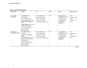
... DIMM sockets DDR2-400 240-pin ECC Registered DIMMs Supported DIMM sizes: 256 MB, 512 MB, 1 GB, 2 GB 16 GB Maximum Dual channel architecture Memory Mirroring Memory Sparing One PCI Express* x8 N/A One PCI Express x4 One PCI-X* 133MHz Two PCI-X 100MHz One PCI 32-bit / 33MHz 5V One PCI Express* x8 N/A One PCI Express x4 One PCI-X* 133MHz Two PCI-X 100MHz One PCI 32-bit / 33MHz 5V SATA USB Connections Dual serial ATA channels with support for RAID 0 and 1. One IDE connector supporting two...
... DIMM sockets DDR2-400 240-pin ECC Registered DIMMs Supported DIMM sizes: 256 MB, 512 MB, 1 GB, 2 GB 16 GB Maximum Dual channel architecture Memory Mirroring Memory Sparing One PCI Express* x8 N/A One PCI Express x4 One PCI-X* 133MHz Two PCI-X 100MHz One PCI 32-bit / 33MHz 5V One PCI Express* x8 N/A One PCI Express x4 One PCI-X* 133MHz Two PCI-X 100MHz One PCI 32-bit / 33MHz 5V SATA USB Connections Dual serial ATA channels with support for RAID 0 and 1. One IDE connector supporting two...
User Guide
Page 15
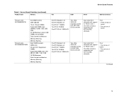
... One IDE connector supporting two ATA/100 IDE channels. Two at front of board One PCI Express* x8 One PCI Express x4 One PCI-X* 133MHz Two PCI-X 100MHz One PCI 32-bit / 33MHz 5V Two Ultra320/LVD channels via the LSI* 53C1030 SCSI controller Dual serial ATA channels with support for RAID 0 and 1. Server Board Varieties (continued) Product Code Memory PCI SCSI SATA USB Connections Product code SE7520BD2SCSI Product code SE7520BD2SCSID2 Six DIMM sockets DDR 266/333 72-bit, 184-pin DIMMs Supported DIMM sizes...
... One IDE connector supporting two ATA/100 IDE channels. Two at front of board One PCI Express* x8 One PCI Express x4 One PCI-X* 133MHz Two PCI-X 100MHz One PCI 32-bit / 33MHz 5V Two Ultra320/LVD channels via the LSI* 53C1030 SCSI controller Dual serial ATA channels with support for RAID 0 and 1. Server Board Varieties (continued) Product Code Memory PCI SCSI SATA USB Connections Product code SE7520BD2SCSI Product code SE7520BD2SCSID2 Six DIMM sockets DDR 266/333 72-bit, 184-pin DIMMs Supported DIMM sizes...
User Guide
Page 16
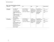
... of board - One IDE connector supporting two ATA/100 IDE channels. Server Board Features Table 1. Two at front of board 16 Four: - Server Board Varieties (continued) Product Code Memory PCI SCSI SATA USB Connections Product code SE7520BD2V Product code SE7520BD2VD2 Six DIMM sockets DDR 266/333 72-bit, 184-pin DIMMs Supported DIMM sizes: 256MB, 512MB, 1GB, 2GB, 4GB 24 GB Maximum (when 4 GB DIMMs are available) Dual channel architecture Memory Mirroring Memory Sparing Eight DIMM sockets...
... of board - One IDE connector supporting two ATA/100 IDE channels. Server Board Features Table 1. Two at front of board 16 Four: - Server Board Varieties (continued) Product Code Memory PCI SCSI SATA USB Connections Product code SE7520BD2V Product code SE7520BD2VD2 Six DIMM sockets DDR 266/333 72-bit, 184-pin DIMMs Supported DIMM sizes: 256MB, 512MB, 1GB, 2GB, 4GB 24 GB Maximum (when 4 GB DIMMs are available) Dual channel architecture Memory Mirroring Memory Sparing Eight DIMM sockets...
User Guide
Page 17
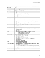
... chipset: ƒ Supports 800 MHz Front Side Bus (FSB) ƒ Intel® E7520 Memory Controller Hub (MCH) ƒ Intel® 6700PXH 64-bit PCI Hub ƒ Intel® 82801ER I/O Controller Hub5 (ICH-5R) I/O Control Video Hard Disk Drive LAN Super I/O controller chip that provides: ƒ Two stacked and interchangeable PS/2 compatible keyboard/mouse ports ƒ USB ports: See Table 1 ƒ One external serial port on the rear I/O port area (Serial A) ƒ One serial port header to provide a second, optional serial port (Serial B) ƒ One IDE connector supporting up...
... chipset: ƒ Supports 800 MHz Front Side Bus (FSB) ƒ Intel® E7520 Memory Controller Hub (MCH) ƒ Intel® 6700PXH 64-bit PCI Hub ƒ Intel® 82801ER I/O Controller Hub5 (ICH-5R) I/O Control Video Hard Disk Drive LAN Super I/O controller chip that provides: ƒ Two stacked and interchangeable PS/2 compatible keyboard/mouse ports ƒ USB ports: See Table 1 ƒ One external serial port on the rear I/O port area (Serial A) ƒ One serial port header to provide a second, optional serial port (Serial B) ƒ One IDE connector supporting up...
User Guide
Page 19
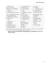
... Rage XL Graphics Controller F, Left x8 (x4speed) PCI-Express* Slot F, Right x8 PCI-Express Slot G Intel® 82541P1 (10/100/1000) H PCI-X 133 Slot I Battery P CPU Power Connector Q DIMM Sockets R CPU 1 Fan Header S CPU 1 T CPU 2 U Intel® Management Module Connector V IDE Connector W Floppy Connector X System Fan 2 (3-pin) Y System Fan 2 (2-pin) Z System Fan 1 (2-pin) J ICMB Connector K System Fan 5 L System Fan 6 M System I/O Connectors N Auxiliary Power Connector O Main Power Connector AA HSBP A BB Front Panel USB CC Front Panel LCP DD IPMB EE SATA A2 FF Speaker GG SATA A1 HH HSBP...
... Rage XL Graphics Controller F, Left x8 (x4speed) PCI-Express* Slot F, Right x8 PCI-Express Slot G Intel® 82541P1 (10/100/1000) H PCI-X 133 Slot I Battery P CPU Power Connector Q DIMM Sockets R CPU 1 Fan Header S CPU 1 T CPU 2 U Intel® Management Module Connector V IDE Connector W Floppy Connector X System Fan 2 (3-pin) Y System Fan 2 (2-pin) Z System Fan 1 (2-pin) J ICMB Connector K System Fan 5 L System Fan 6 M System I/O Connectors N Auxiliary Power Connector O Main Power Connector AA HSBP A BB Front Panel USB CC Front Panel LCP DD IPMB EE SATA A2 FF Speaker GG SATA A1 HH HSBP...
User Guide
Page 21
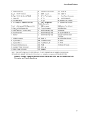
... PCI Slot 32/33 E ATI* Rage XL Graphics Controller F, Left x8 (x4speed) PCI-Express* Slot F, Right x8 PCI-Express Slot G Intel® 82541P1 (10/100/1000) H PCI-X 133 Slot I Battery J ICMB Connector K System Fan 5 L System Fan 6 M System I/O Connectors N Auxiliary Power Connector O Main Power Connector P CPU Power Connector Q DIMM Sockets R CPU 1 Fan Header S CPU 1 T CPU 2 U Intel® Management Module Connector V IDE Connector W Floppy Connector X System Fan 2 (3-pin) Y System Fan 2 (2-pin) Z System Fan 1 (2-pin) AA HSBP A BB Front Panel USB CC Front Panel LCP DD IPMB EE SATA A2 FF Speaker...
... PCI Slot 32/33 E ATI* Rage XL Graphics Controller F, Left x8 (x4speed) PCI-Express* Slot F, Right x8 PCI-Express Slot G Intel® 82541P1 (10/100/1000) H PCI-X 133 Slot I Battery J ICMB Connector K System Fan 5 L System Fan 6 M System I/O Connectors N Auxiliary Power Connector O Main Power Connector P CPU Power Connector Q DIMM Sockets R CPU 1 Fan Header S CPU 1 T CPU 2 U Intel® Management Module Connector V IDE Connector W Floppy Connector X System Fan 2 (3-pin) Y System Fan 2 (2-pin) Z System Fan 1 (2-pin) AA HSBP A BB Front Panel USB CC Front Panel LCP DD IPMB EE SATA A2 FF Speaker...
User Guide
Page 24
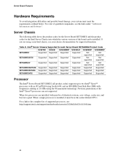
... and Software". Intel® Server Chassis Supported for support information. For a list of identical revision, core voltage, cache size, and bus/core speed. If you are using the 90-nanometer technology. When two processors are not supported. Previous generations of the board can be installed. Server Chassis The following table shows the product codes for the Server Board SE7520BD2 and the product codes for the Intel Server Chassis into which the various versions of the Intel...
... and Software". Intel® Server Chassis Supported for support information. For a list of identical revision, core voltage, cache size, and bus/core speed. If you are using the 90-nanometer technology. When two processors are not supported. Previous generations of the board can be installed. Server Chassis The following table shows the product codes for the Server Board SE7520BD2 and the product codes for the Intel Server Chassis into which the various versions of the Intel...
User Guide
Page 25
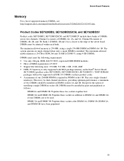
... DIMM sockets 1A and 1B. Channel B consists of supported memory DIMMs, see: http://support.intel.com/support/motherboards/server/se7520bd2/sb/CS-013543.htm. However, for the option of two DIMMs should be used. DIMMs must meet the following requirements: ƒ Use only 184-pin, DDR-266/333 ECC, registered DDR DIMM modules ƒ Have a DIMM organization x72 ECC ƒ Support the following sizes...
... DIMM sockets 1A and 1B. Channel B consists of supported memory DIMMs, see: http://support.intel.com/support/motherboards/server/se7520bd2/sb/CS-013543.htm. However, for the option of two DIMMs should be used. DIMMs must meet the following requirements: ƒ Use only 184-pin, DDR-266/333 ECC, registered DDR DIMM modules ƒ Have a DIMM organization x72 ECC ƒ Support the following sizes...
User Guide
Page 26
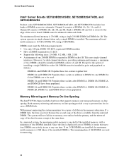
.... Memory Mirroring and Memory On-line Sparing The Intel® E7520 chipset includes hardware that up to memory error unless both the primary and the mirrored copy of installing a single DIMM in socket 1B, DIMMs must meet the following requirements: ƒ Use only 240-pin, DDR2-400 ECC, registered DIMM modules ƒ Have a DIMM organization x72 ECC ƒ Support the following sizes...
.... Memory Mirroring and Memory On-line Sparing The Intel® E7520 chipset includes hardware that up to memory error unless both the primary and the mirrored copy of installing a single DIMM in socket 1B, DIMMs must meet the following requirements: ƒ Use only 240-pin, DDR2-400 ECC, registered DIMM modules ƒ Have a DIMM organization x72 ECC ƒ Support the following sizes...
User Guide
Page 40
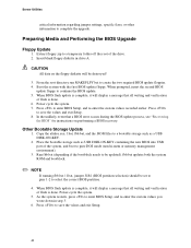
... the upgrade. Boot the system with the first BIOS update floppy. Power cycle the system. 7. Place the bootable storage such as a USB DISK-ON-KEY. 2. Power-cycle the system. 5. Server Utilities critical information regarding jumper settings, specific fixes, or other information to create the two required BIOS update floppies. 4. Preparing Media and Performing the BIOS Upgrade Floppy Update 1. Extract floppy.zip to pure DOS mode (non hi-mem or memory management environment). 3. Insert blank floppy diskette...
... the upgrade. Boot the system with the first BIOS update floppy. Power cycle the system. 7. Place the bootable storage such as a USB DISK-ON-KEY. 2. Power-cycle the system. 5. Server Utilities critical information regarding jumper settings, specific fixes, or other information to create the two required BIOS update floppies. 4. Preparing Media and Performing the BIOS Upgrade Floppy Update 1. Extract floppy.zip to pure DOS mode (non hi-mem or memory management environment). 3. Insert blank floppy diskette...
User Guide
Page 46
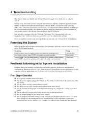
... by an incorrect installation or configuration. Clear system memory, restart POST, and reload the operating system. Press: Reset button Power off and then on Problems following methods. Firmware upgrades include updates for example, two add-in ? If applicable, ensure that there are using the latest firmware and files. Resetting the System Before going through in-depth troubleshooting, first attempt to the server firmware and files, also update any drivers used for assistance...
... by an incorrect installation or configuration. Clear system memory, restart POST, and reload the operating system. Press: Reset button Power off and then on Problems following methods. Firmware upgrades include updates for example, two add-in ? If applicable, ensure that there are using the latest firmware and files. Resetting the System Before going through in-depth troubleshooting, first attempt to the server firmware and files, also update any drivers used for assistance...
User Guide
Page 47
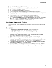
... the peripheral devices. 1. Hardware Diagnostic Testing This section provides a more detailed approach to identifying a hardware problem and locating its brightness and contrast controls to the system. Failure to do so can cause permanent damage to the tested component lists. Make sure your video display monitor). 4. If the power LED does not light, see the documentation supplied with your video display monitor and keyboard are correctly connected to at...
... the peripheral devices. 1. Hardware Diagnostic Testing This section provides a more detailed approach to identifying a hardware problem and locating its brightness and contrast controls to the system. Failure to do so can cause permanent damage to the tested component lists. Make sure your video display monitor). 4. If the power LED does not light, see the documentation supplied with your video display monitor and keyboard are correctly connected to at...
User Guide
Page 51
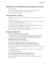
... the current version. ‰ Make sure the other PCI drivers. Problems with Network The server hangs when the drivers are loaded. ‰ Certain drivers may be necessary to the port from the on-board network controller. ‰ Make sure your PCI card(s) for a link to the correct connector at the system back panel. ‰ Try a different network cable. ‰ Make sure you specify the correct frame type in your...
... the current version. ‰ Make sure the other PCI drivers. Problems with Network The server hangs when the drivers are loaded. ‰ Certain drivers may be necessary to the port from the on-board network controller. ‰ Make sure your PCI card(s) for a link to the correct connector at the system back panel. ‰ Try a different network cable. ‰ Make sure you specify the correct frame type in your...
User Guide
Page 52
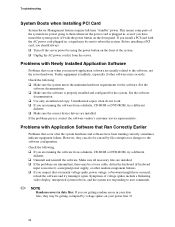
... user commands. ✏ NOTE Random errors in your power line. If the problems persist, contact the software vendor's customer service representative. This means some parts of voltage spikes include a flickering video display, unexpected system reboots, and the system not responding to them whenever the power cord is properly installed and configured for the software. Before installing a PCI card, you are running correctly sometimes indicate equipment failure. If 52 Problems...
... user commands. ✏ NOTE Random errors in your power line. If the problems persist, contact the software vendor's customer service representative. This means some parts of voltage spikes include a flickering video display, unexpected system reboots, and the system not responding to them whenever the power cord is properly installed and configured for the software. Before installing a PCI card, you are running correctly sometimes indicate equipment failure. If 52 Problems...
User Guide
Page 53
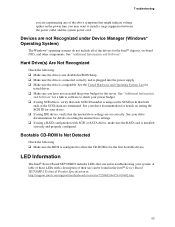
... installed correctly and properly configured. See your system. Hard Drive(s) Are Not Recognized Check the following : ‰ Make sure the BIOS is compatible. Troubleshooting you are set correctly. Bootable CD-ROM Is Not Detected Check the following : ‰ Make sure the drive is not disabled in BIOS Setup. ‰ Make sure the drive is connected correctly and is plugged into the power supply. ‰ Make sure the drive is configured...
... installed correctly and properly configured. See your system. Hard Drive(s) Are Not Recognized Check the following : ‰ Make sure the BIOS is compatible. Troubleshooting you are set correctly. Bootable CD-ROM Is Not Detected Check the following : ‰ Make sure the drive is not disabled in BIOS Setup. ‰ Make sure the drive is connected correctly and is plugged into the power supply. ‰ Make sure the drive is configured...
User Guide
Page 54
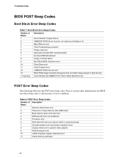
... (processor exception error) 8 Display memory error (system video adapter) 9 ROM checksum error 10 CMOS shutdown register read error 6 Keyboard controller BAT command failed 7 No Flash EPROM detected 8 Floppy controller failure 9 Boot Block BIOS checksum error 10 Flash Erase error 11 Flash Program error 12 'AMIBOOT.ROM' file size error 13 BIOS ROM image mismatch (file layout does not match image present in root directory of error conditions. Table 8. Boot Block Error Beep Codes Number of Beeps Description 1 Insert diskette in floppy drive A: 2 'AMIBOOT.ROM...
... (processor exception error) 8 Display memory error (system video adapter) 9 ROM checksum error 10 CMOS shutdown register read error 6 Keyboard controller BAT command failed 7 No Flash EPROM detected 8 Floppy controller failure 9 Boot Block BIOS checksum error 10 Flash Erase error 11 Flash Program error 12 'AMIBOOT.ROM' file size error 13 BIOS ROM image mismatch (file layout does not match image present in root directory of error conditions. Table 8. Boot Block Error Beep Codes Number of Beeps Description 1 Insert diskette in floppy drive A: 2 'AMIBOOT.ROM...


