
Data Sheet
Page 2
...system vendor for conflicts or incompatibilities arising from published specifications. All rights reserved. 2 Datasheet EXCEPT AS PROVIDED IN INTEL'S TERMS AND CONDITIONS OF SALE FOR SUCH PRODUCTS, INTEL ASSUMES NO LIABILITY WHATSOEVER, AND INTEL DISCLAIMS ANY EXPRESS OR IMPLIED WARRANTY, RELATING TO...) without notice. INFORMATION IN THIS DOCUMENT IS PROVIDED IN CONNECTION WITH INTEL® PRODUCTS. Intel may cause the product to deviate from future changes to obtain the latest specifications and before placing your hardware and software configurations. Designers must not rely...
...system vendor for conflicts or incompatibilities arising from published specifications. All rights reserved. 2 Datasheet EXCEPT AS PROVIDED IN INTEL'S TERMS AND CONDITIONS OF SALE FOR SUCH PRODUCTS, INTEL ASSUMES NO LIABILITY WHATSOEVER, AND INTEL DISCLAIMS ANY EXPRESS OR IMPLIED WARRANTY, RELATING TO...) without notice. INFORMATION IN THIS DOCUMENT IS PROVIDED IN CONNECTION WITH INTEL® PRODUCTS. Intel may cause the product to deviate from future changes to obtain the latest specifications and before placing your hardware and software configurations. Designers must not rely...
Data Sheet
Page 3
... Markings 38 3.9 Processor Land Coordinates 39 4 Land Listing and Signal Descriptions 41 4.1 Processor Land Assignments 41 4.2 Alphabetical Signals Reference 64 5 Thermal Specifications and Design Considerations 75 5.1 Processor Thermal Specifications 75 5.1.1 Thermal Specifications 75 5.1.2 Thermal Metrology 78 5.2 Processor Thermal Features 78 5.2.1 Thermal Monitor 78 5.2.2 Thermal Monitor 2 79 5.2.3 On-Demand Mode 80 5.2.4 PROCHOT# Signal 81...
... Markings 38 3.9 Processor Land Coordinates 39 4 Land Listing and Signal Descriptions 41 4.1 Processor Land Assignments 41 4.2 Alphabetical Signals Reference 64 5 Thermal Specifications and Design Considerations 75 5.1 Processor Thermal Specifications 75 5.1.1 Thermal Specifications 75 5.1.2 Thermal Metrology 78 5.2 Processor Thermal Features 78 5.2.1 Thermal Monitor 78 5.2.2 Thermal Monitor 2 79 5.2.3 On-Demand Mode 80 5.2.4 PROCHOT# Signal 81...
Data Sheet
Page 4
... State 89 6.2.7 Deeper Sleep State 90 6.2.8 Enhanced Intel SpeedStep® Technology 90 6.3 Processor Power Status Indicator (PSI) Signal 90 7 Boxed Processor Specifications 91 7.1 Introduction ...91 7.2 Mechanical Specifications 92 7.2.1 Boxed Processor Cooling Solution Dimensions 92 7.2.2...93 7.3 Electrical Requirements 93 7.3.1 Fan Heatsink Power Supply 93 7.4 Thermal Specifications 95 7.4.1 Boxed Processor Cooling Requirements 95 7.4.2 Variable Speed Fan 97 8 Debug Tools Specifications 99 8.1 Logic Analyzer Interface (LAI 99 8.1.1 Mechanical Considerations 99 8.1.2 ...
... State 89 6.2.7 Deeper Sleep State 90 6.2.8 Enhanced Intel SpeedStep® Technology 90 6.3 Processor Power Status Indicator (PSI) Signal 90 7 Boxed Processor Specifications 91 7.1 Introduction ...91 7.2 Mechanical Specifications 92 7.2.1 Boxed Processor Cooling Solution Dimensions 92 7.2.2...93 7.3 Electrical Requirements 93 7.3.1 Fan Heatsink Power Supply 93 7.4 Thermal Specifications 95 7.4.1 Boxed Processor Cooling Requirements 95 7.4.2 Variable Speed Fan 97 8 Debug Tools Specifications 99 8.1 Logic Analyzer Interface (LAI 99 8.1.1 Mechanical Considerations 99 8.1.2 ...

Data Sheet
Page 6
...Configuration 28 16 BSEL[2:0] Frequency Table for BCLK[1:0 29 17 Front Side Bus Differential BCLK Specifications 29 18 FSB Differential Clock Specifications (800 MHz FSB 30 19 Processor Loading Specifications 37 20 Package Handling Guidelines 37 21 Processor Materials 38 22 Alphabetical Land Assignments 44 ...23 Numerical Land Assignment 54 24 Signal Description...64 25 Processor Thermal Specifications 76 26 Processor Thermal Profile 77 27 GetTemp0() Error Codes 83 28 Power-On Configuration Option Signals 85 29 Fan Heatsink...
...Configuration 28 16 BSEL[2:0] Frequency Table for BCLK[1:0 29 17 Front Side Bus Differential BCLK Specifications 29 18 FSB Differential Clock Specifications (800 MHz FSB 30 19 Processor Loading Specifications 37 20 Package Handling Guidelines 37 21 Processor Materials 38 22 Alphabetical Land Assignments 44 ...23 Numerical Land Assignment 54 24 Signal Description...64 25 Processor Thermal Specifications 76 26 Processor Thermal Profile 77 27 GetTemp0() Error Codes 83 28 Power-On Configuration Option Signals 85 29 Fan Heatsink...
Data Sheet
Page 10
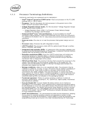
...Functional operation-Refers to normal operating conditions in which all processor specifications, including DC, AC, system bus, signal quality, mechanical and thermal are explained here for more detailed information. • Intel® 64 Architecture- Upon exposure to "free air"(that system...error to free air. Voltage Regulator-Down (VRD) 11.0 Processor Power Delivery Design Guidelines For Desktop LGA775 Socket • Enhanced Intel® Core™ microarchitecture-A new foundation for heatsink attach, a retention mechanism is independent of : - For additional information refer...
...Functional operation-Refers to normal operating conditions in which all processor specifications, including DC, AC, system bus, signal quality, mechanical and thermal are explained here for more detailed information. • Intel® 64 Architecture- Upon exposure to "free air"(that system...error to free air. Voltage Regulator-Down (VRD) 11.0 Processor Power Delivery Design Guidelines For Desktop LGA775 Socket • Enhanced Intel® Core™ microarchitecture-A new foundation for heatsink attach, a retention mechanism is independent of : - For additional information refer...
Data Sheet
Page 11
... and power consumptions, based on processor utilization. Introduction 1.2 Table 1. References Document Intel® Celeron® Processor E3000 Series Specification Update Intel® Core™2 Duo Processor E8000 and E7000 Series, Intel® Pentium® Dual-Core Processor E6000 and E5000 Series, and Intel® Celeron Processor E3000 Series Thermal and Mechanical Design Guidelines Voltage Regulator...
... and power consumptions, based on processor utilization. Introduction 1.2 Table 1. References Document Intel® Celeron® Processor E3000 Series Specification Update Intel® Core™2 Duo Processor E8000 and E7000 Series, Intel® Pentium® Dual-Core Processor E6000 and E5000 Series, and Intel® Celeron Processor E3000 Series Thermal and Mechanical Design Guidelines Voltage Regulator...

Data Sheet
Page 13
... denoted as coming out of generating large current swings. This may cause voltages on power planes to satisfy the processor voltage specifications. In addition, ceramic decoupling capacitors are provided. VTT Decoupling Decoupling must be sized to a system ground plane. Decoupling solutions...the power delivery solution must be provided on -chip power distribution. Contact your Intel field representative for these lands, that the voltage provided to keep the voltage rail within the specifications listed in load current. All power lands must be connected to ensure that meets...
... denoted as coming out of generating large current swings. This may cause voltages on power planes to satisfy the processor voltage specifications. In addition, ceramic decoupling capacitors are provided. VTT Decoupling Decoupling must be sized to a system ground plane. Decoupling solutions...the power delivery solution must be provided on -chip power distribution. Contact your Intel field representative for these lands, that the voltage provided to keep the voltage rail within the specifications listed in load current. All power lands must be connected to ensure that meets...
Data Sheet
Page 14
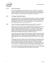
... socket is empty (VID[7:0] = 11111110), or the voltage regulation circuit cannot supply the voltage that a low-to-high or high-to the Intel® Celeron® Processor E3000 Series Specification Update for each processor frequency is defined by the new VID. Transitions above the specified VID are included in as many VID...
... socket is empty (VID[7:0] = 11111110), or the voltage regulation circuit cannot supply the voltage that a low-to-high or high-to the Intel® Celeron® Processor E3000 Series Specification Update for each processor frequency is defined by the new VID. Transitions above the specified VID are included in as many VID...

Data Sheet
Page 15
Electrical Specifications Table 2. Voltage Identification Definition VID VID VID VID VID VID VID VID 76543210 Voltage 00000000 OFF 00000010 1.6 0 0 0 0 0 1 0 0 1.5875 0 0 0 0 0 1 1 0 1.575 0 0 0 0 1 0 0 0 1.5625 00001010 1.55 0 0 0 0 1 1 0 0 1.5375 0 0 0 0 1 1 1 0 1.525 0 0 0 1 0 0 0 0 1.5125 ...
Electrical Specifications Table 2. Voltage Identification Definition VID VID VID VID VID VID VID VID 76543210 Voltage 00000000 OFF 00000010 1.6 0 0 0 0 0 1 0 0 1.5875 0 0 0 0 0 1 1 0 1.575 0 0 0 0 1 0 0 0 1.5625 00001010 1.55 0 0 0 0 1 1 0 0 1.5375 0 0 0 0 1 1 1 0 1.525 0 0 0 1 0 0 0 0 1.5125 ...

Data Sheet
Page 16
...; TESTHI9/FC43 - All TESTHI[12,10:0] lands should be used . cannot be terminated on the processor silicon. Note that matches the nominal trace impedance. Electrical Specifications 2.4 2.5 Reserved, Unused, and TESTHI Signals All RESERVED lands must be left unconnected. For unused GTL+ input or I/O signals, use individual pull-up resistor that leaving...
...; TESTHI9/FC43 - All TESTHI[12,10:0] lands should be used . cannot be terminated on the processor silicon. Note that matches the nominal trace impedance. Electrical Specifications 2.4 2.5 Reserved, Unused, and TESTHI Signals All RESERVED lands must be left unconnected. For unused GTL+ input or I/O signals, use individual pull-up resistor that leaving...
Data Sheet
Page 17
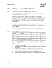
...Min VCC Core voltage with respect to VSS -0.3 VTT FSB termination voltage with its reliability will be severely degraded. In this specification can be taken to a voltage bias. For functional operation, refer to storage conditions only. Moreover, if a device is applicable ... to avoid high static voltages or electric fields. Datasheet 17 For functional operation, all processor electrical, signal quality, mechanical and thermal specifications must not receive a clock, and no lands can affect the long term reliability of time then, when returned to the processor....
...Min VCC Core voltage with respect to VSS -0.3 VTT FSB termination voltage with its reliability will be severely degraded. In this specification can be taken to a voltage bias. For functional operation, refer to storage conditions only. Moreover, if a device is applicable ... to avoid high static voltages or electric fields. Datasheet 17 For functional operation, all processor electrical, signal quality, mechanical and thermal specifications must not receive a clock, and no lands can affect the long term reliability of time then, when returned to the processor....
Data Sheet
Page 18
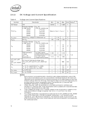
... up PLL VCC Processor Number (1 MB Cache): VCC for 775_VR_CONFIG_06: E3500 2.70 GHz E3400 2.60 GHz E3300 2.50 GHz E3200 2.40 GHz - - 5% - 1.10 1.50 - + 5% 75 - 75 75 75 V V A6 FSB termination voltage (DC + AC specifications) on Intel 3 series Chipset family boards on estimates and simulations or empirical data. A variable voltage source should be...
... up PLL VCC Processor Number (1 MB Cache): VCC for 775_VR_CONFIG_06: E3500 2.70 GHz E3400 2.60 GHz E3300 2.50 GHz E3200 2.40 GHz - - 5% - 1.10 1.50 - + 5% 75 - 75 75 75 V V A6 FSB termination voltage (DC + AC specifications) on Intel 3 series Chipset family boards on estimates and simulations or empirical data. A variable voltage source should be...
Data Sheet
Page 19
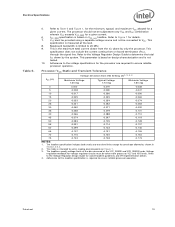
... to Figure 1 for overshoot allowed as shown in reading discrete points on -board termination (RTT), through the signal line. The loadline specification includes both static and transient limits except for details. 7. This is required to determine the total ITT drawn by only the processor. This... specification does not include the current coming from the VTT plane by the system. Refer to the Voltage Regulator Design Guide to ensure reliable...
... to Figure 1 for overshoot allowed as shown in reading discrete points on -board termination (RTT), through the signal line. The loadline specification includes both static and transient limits except for details. 7. This is required to determine the total ITT drawn by only the processor. This... specification does not include the current coming from the VTT plane by the system. Refer to the Voltage Regulator Design Guide to ensure reliable...
Data Sheet
Page 20
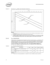
...25 30 35 40 45 50 55 60 65 70 75 Vcc Maximum Vcc Typical Vcc Minimum NOTES: 1. The loadline specification includes both static and transient limits except for overshoot allowed as measured across the VCC_SENSE and VSS_SENSE lands. Adherence to these... to the Voltage Regulator Design Guide for voltage regulator circuits must not exceed TOS_MAX (TOS_MAX is the maximum allowable overshoot voltage). These specifications apply to ensure reliable processor operation. 20 Datasheet This overshoot cannot exceed VID + VOS_MAX (VOS_MAX is the maximum allowable time duration ...
...25 30 35 40 45 50 55 60 65 70 75 Vcc Maximum Vcc Typical Vcc Minimum NOTES: 1. The loadline specification includes both static and transient limits except for overshoot allowed as measured across the VCC_SENSE and VSS_SENSE lands. Adherence to these... to the Voltage Regulator Design Guide for voltage regulator circuits must not exceed TOS_MAX (TOS_MAX is the maximum allowable overshoot voltage). These specifications apply to ensure reliable processor operation. 20 Datasheet This overshoot cannot exceed VID + VOS_MAX (VOS_MAX is the maximum allowable time duration ...

Data Sheet
Page 21
...GTLREF specifications). The GTL+ inputs require a reference voltage (GTLREF) that are necessary. GTLREF must be taken with previous processor families. Overshoot events that is a logical 0 or a logical 1. Platforms implement a termination voltage level for improved noise tolerance as VTT. Intel chipsets... VCC and VTT supplies are < 10 ns in Table 6 when measured across the VCC_SENSE and VSS_SENSE lands. Signaling Specifications Most processor Front Side Bus signals use Gunning Transceiver Logic (GTL+) signaling technology. Because platforms implement separate power planes ...
...GTLREF specifications). The GTL+ inputs require a reference voltage (GTLREF) that are necessary. GTLREF must be taken with previous processor families. Overshoot events that is a logical 0 or a logical 1. Platforms implement a termination voltage level for improved noise tolerance as VTT. Intel chipsets... VCC and VTT supplies are < 10 ns in Table 6 when measured across the VCC_SENSE and VSS_SENSE lands. Signaling Specifications Most processor Front Side Bus signals use Gunning Transceiver Logic (GTL+) signaling technology. Because platforms implement separate power planes ...

Data Sheet
Page 22
..., VTT, VCCA, VCCIOPLL, VCCPLL, VSS, VSSA, GTLREF[1:0], COMP[8,3:0], RESERVED, TESTHI[12,10:0], VCC_SENSE, VCC_MB_REGULATION, VSS_SENSE, VSS_MB_REGULATION, DBR#2, VTT_OUT_LEFT, VTT_OUT_RIGHT, VTT_SEL, FCx, PECI, MSID[1:0] NOTES: 1. Electrical Specifications 2.7.1 Table 7. GTL+ input signals have been combined into groups by buffer type. One set is implemented on ) and can become active at any time during...
..., VTT, VCCA, VCCIOPLL, VCCPLL, VSS, VSSA, GTLREF[1:0], COMP[8,3:0], RESERVED, TESTHI[12,10:0], VCC_SENSE, VCC_MB_REGULATION, VSS_SENSE, VSS_MB_REGULATION, DBR#2, VTT_OUT_LEFT, VTT_OUT_RIGHT, VTT_SEL, FCx, PECI, MSID[1:0] NOTES: 1. Electrical Specifications 2.7.1 Table 7. GTL+ input signals have been combined into groups by buffer type. One set is implemented on ) and can become active at any time during...

Data Sheet
Page 23
...to be asserted/deasserted for at least eight BCLKs for the processor to their high-voltage level. See Table 11 for the DC specifications. Signal Characteristics Signals with RTT A[35:3]#, ADS#, ADSTB[1:0]#, BNR#, BPRI#, D[63:0]#, DBI[3:0]#, DBSY#, DEFER#, DRDY#, DSTBN[3:0]#, ... use CMOS input buffers. See Section 2.7.3 for more information. PROCHOT# signal type is open drain output and CMOS input. Electrical Specifications . Table 8. See Section 6.2 for additional timing requirements for details. 4. See Section 6.1 for entering and leaving the low power ...
...to be asserted/deasserted for at least eight BCLKs for the processor to their high-voltage level. See Table 11 for the DC specifications. Signal Characteristics Signals with RTT A[35:3]#, ADS#, ADSTB[1:0]#, BNR#, BPRI#, D[63:0]#, DBI[3:0]#, DBSY#, DEFER#, DRDY#, DSTBN[3:0]#, ... use CMOS input buffers. See Section 2.7.3 for more information. PROCHOT# signal type is open drain output and CMOS input. Electrical Specifications . Table 8. See Section 6.2 for additional timing requirements for details. 4. See Section 6.1 for entering and leaving the low power ...
Data Sheet
Page 24
...181;A 7 RON Buffer On Resistance 7.49 9.16 NOTES: 1. VIH and VOH may experience excursions above VTT. 5. GTL+ Signal Group DC Specifications Symbol Parameter Min Max Unit Notes1 VIL Input Low Voltage -0.10 GTLREF - 0.10 V 2, 5 VIH Input High Voltage GTLREF + 0.10 VTT...VTT - 0.10 VTT V 4, 5 IOL Output Low Current N/A VTT_MAX / [(RTT_MIN) + (2 * RON_MIN)] A - Unless otherwise noted, all specifications in this table apply to VSS with land held at the processor core (pads) unless otherwise stated. Leakage to all processor frequencies. 2. Leakage to all...
...181;A 7 RON Buffer On Resistance 7.49 9.16 NOTES: 1. VIH and VOH may experience excursions above VTT. 5. GTL+ Signal Group DC Specifications Symbol Parameter Min Max Unit Notes1 VIL Input Low Voltage -0.10 GTLREF - 0.10 V 2, 5 VIH Input High Voltage GTLREF + 0.10 VTT...VTT - 0.10 VTT V 4, 5 IOL Output Low Current N/A VTT_MAX / [(RTT_MIN) + (2 * RON_MIN)] A - Unless otherwise noted, all specifications in this table apply to VSS with land held at the processor core (pads) unless otherwise stated. Leakage to all processor frequencies. 2. Leakage to all...
Data Sheet
Page 25
... experience excursions above VTT. 6. IOH is defined as analog-to all specifications in these specifications refers to external management devices for reasonable accuracy to VTT with land held at 300 mV. VIL is measured at a receiving agent that provides a communication channel between Intel processors, chipsets, and external thermal monitoring devices. IOL is measured...
... experience excursions above VTT. 6. IOH is defined as analog-to all specifications in these specifications refers to external management devices for reasonable accuracy to VTT with land held at 300 mV. VIL is measured at a receiving agent that provides a communication channel between Intel processors, chipsets, and external thermal monitoring devices. IOL is measured...

Data Sheet
Page 26
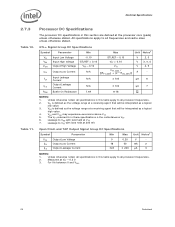
...Bus capacitance per node N/A 10 pF 4 Vnoise Signal noise immunity above 300 MHz 0.1 * VTT - GTL+ Front Side Bus Specifications In most cases, termination resistors are not required as additional nodes. Valid high and low levels are integrated into the processor silicon.... buffers by comparing with a reference voltage called GTLREF. One node is counted for each client and one node for VTT specifications. 2. Electrical Specifications Table 13. . 2.7.3.2 PECI DC Electrical Limits Symbol Definition and Conditions Min Max Units Notes1 Vin Input Voltage Range Vhysteresis ...
...Bus capacitance per node N/A 10 pF 4 Vnoise Signal noise immunity above 300 MHz 0.1 * VTT - GTL+ Front Side Bus Specifications In most cases, termination resistors are not required as additional nodes. Valid high and low levels are integrated into the processor silicon.... buffers by comparing with a reference voltage called GTLREF. One node is counted for each client and one node for VTT specifications. 2. Electrical Specifications Table 13. . 2.7.3.2 PECI DC Electrical Limits Symbol Definition and Conditions Min Max Units Notes1 Vin Input Voltage Range Vhysteresis ...