
Data Sheet
Page 2
... a processor with a processor, chipset, BIOS, operating system, device drivers and applications enabled for conflicts or incompatibilities arising from published specifications. The Intel Celeron® processor E3000 series may be claimed as errata which processors support Intel 64 or consult with your PC manufacturer on your system delivers Execute Disable Bit functionality. ‡ Not all specified units of this processor support Enhanced Intel SpeedStep® Technology. Intel processor numbers...
... a processor with a processor, chipset, BIOS, operating system, device drivers and applications enabled for conflicts or incompatibilities arising from published specifications. The Intel Celeron® processor E3000 series may be claimed as errata which processors support Intel 64 or consult with your PC manufacturer on your system delivers Execute Disable Bit functionality. ‡ Not all specified units of this processor support Enhanced Intel SpeedStep® Technology. Intel processor numbers...
Data Sheet
Page 3
... 2.6.3 VCC Overshoot 20 2.6.4 Die Voltage Validation 21 2.7 Signaling Specifications 21 2.7.1 FSB Signal Groups 22 2.7.2 CMOS and Open Drain Signals 23 2.7.3 Processor DC Specifications 24 2.7.3.1 Platform Environment Control Interface (PECI) DC Specifications..... 25 2.7.3.2 GTL+ Front Side Bus Specifications 26 2.8 Clock Specifications 27 2.8.1 Front Side Bus Clock (BCLK[1:0]) and Processor Clocking 27 2.8.2 FSB Frequency Select Signals (BSEL[2:0 28 2.8.3 Phase Lock Loop (PLL...
... 2.6.3 VCC Overshoot 20 2.6.4 Die Voltage Validation 21 2.7 Signaling Specifications 21 2.7.1 FSB Signal Groups 22 2.7.2 CMOS and Open Drain Signals 23 2.7.3 Processor DC Specifications 24 2.7.3.1 Platform Environment Control Interface (PECI) DC Specifications..... 25 2.7.3.2 GTL+ Front Side Bus Specifications 26 2.8 Clock Specifications 27 2.8.1 Front Side Bus Clock (BCLK[1:0]) and Processor Clocking 27 2.8.2 FSB Frequency Select Signals (BSEL[2:0 28 2.8.3 Phase Lock Loop (PLL...
Data Sheet
Page 5
... 22 Boxed Processor Fan Heatsink Power Cable Connector Description 94 23 Baseboard Power Header Placement Relative to Processor Socket 95 24 Boxed Processor Fan Heatsink Airspace Keepout Requirements (side 1 view 96 25 Boxed Processor Fan Heatsink Airspace Keepout Requirements (side 2 view 96 26 Boxed Processor Fan Heatsink Set Points 97 Datasheet 5 Left Side 42 12 land-out Diagram (Top View - Right Side 43 13 Processor Series Thermal Profile 77 14 Case Temperature...
... 22 Boxed Processor Fan Heatsink Power Cable Connector Description 94 23 Baseboard Power Header Placement Relative to Processor Socket 95 24 Boxed Processor Fan Heatsink Airspace Keepout Requirements (side 1 view 96 25 Boxed Processor Fan Heatsink Airspace Keepout Requirements (side 2 view 96 26 Boxed Processor Fan Heatsink Set Points 97 Datasheet 5 Left Side 42 12 land-out Diagram (Top View - Right Side 43 13 Processor Series Thermal Profile 77 14 Case Temperature...
Data Sheet
Page 7
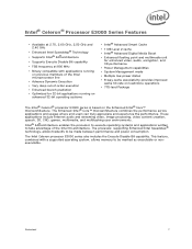
...-bit applications running on the Enhanced Intel® Core™ microarchitecture. Datasheet 7 Intel® Celeron® Processor E3000 Series Features • Available at 2.70, 2.60 GHz, 2.50 GHz and 2.40 GHz • Enhanced Intel Speedstep® Technology • Supports Intel® 64 architecture • Supports Execute Disable Bit capability • FSB frequency at 800 MHz • Binary compatible with a supported operating system, allows memory to be made between performance...
...-bit applications running on the Enhanced Intel® Core™ microarchitecture. Datasheet 7 Intel® Celeron® Processor E3000 Series Features • Available at 2.70, 2.60 GHz, 2.50 GHz and 2.40 GHz • Enhanced Intel Speedstep® Technology • Supports Intel® 64 architecture • Supports Execute Disable Bit capability • FSB frequency at 800 MHz • Binary compatible with a supported operating system, allows memory to be made between performance...
Data Sheet
Page 9
... as the LGA775 socket. Intel has enabled support components for the processor including heatsink, heatsink retention mechanism, and socket. For example, D[3:0] = 'HLHL' refers to a hex 'A', and D[3:0]# = 'LHLH' also refers to frequently used data. In this document, the Intel® Celeron® processor E3000 series may be referred to processors, memory, and I/O. The processors feature the Intel® Advanced Smart Cache, a shared multi-core optimized cache that significantly reduces...
... as the LGA775 socket. Intel has enabled support components for the processor including heatsink, heatsink retention mechanism, and socket. For example, D[3:0] = 'HLHL' refers to a hex 'A', and D[3:0]# = 'LHLH' also refers to frequently used data. In this document, the Intel® Celeron® processor E3000 series may be referred to processors, memory, and I/O. The processors feature the Intel® Advanced Smart Cache, a shared multi-core optimized cache that significantly reduces...
Data Sheet
Page 10
... the socket. • FSB (Front Side Bus)-The electrical interface that is the generic form of the Intel® Celeron® processor E3000 series. • Voltage Regulator Design Guide-For this document "Voltage Regulator Design Guide" may be used to the chipset. Voltage Regulator-Down (VRD) 11.0 Processor Power Delivery Design Guidelines For Desktop LGA775 Socket • Enhanced Intel® Core™ microarchitecture-A new...
... the socket. • FSB (Front Side Bus)-The electrical interface that is the generic form of the Intel® Celeron® processor E3000 series. • Voltage Regulator Design Guide-For this document "Voltage Regulator Design Guide" may be used to the chipset. Voltage Regulator-Down (VRD) 11.0 Processor Power Delivery Design Guidelines For Desktop LGA775 Socket • Enhanced Intel® Core™ microarchitecture-A new...
Data Sheet
Page 11
... Series Specification Update Intel® Core™2 Duo Processor E8000 and E7000 Series, Intel® Pentium® Dual-Core Processor E6000 and E5000 Series, and Intel® Celeron Processor E3000 Series Thermal and Mechanical Design Guidelines Voltage Regulator-Down (VRD) 11.0 Processor Power Delivery Design Guidelines For Desktop LGA775 Socket LGA775 Socket Mechanical Design Guide Intel® 64 and IA-32 Intel Architecture Software Developer's Manuals Volume 1: Basic Architecture Volume 2A: Instruction Set...
... Series Specification Update Intel® Core™2 Duo Processor E8000 and E7000 Series, Intel® Pentium® Dual-Core Processor E6000 and E5000 Series, and Intel® Celeron Processor E3000 Series Thermal and Mechanical Design Guidelines Voltage Regulator-Down (VRD) 11.0 Processor Power Delivery Design Guidelines For Desktop LGA775 Socket LGA775 Socket Mechanical Design Guide Intel® 64 and IA-32 Intel Architecture Software Developer's Manuals Volume 1: Basic Architecture Volume 2A: Instruction Set...
Data Sheet
Page 14
... be delivered to the Intel® Celeron® Processor E3000 Series Specification Update for these signals. The processor uses eight voltage identification signals, VID[7:0], to a low voltage level. Electrical Specifications 2.2.3 2.3 Note: FSB Decoupling The processor integrates signal termination on the processor package. In addition, some of power supply voltages. The Deeper Sleep State also requires additional platform support. This is reflected by...
... be delivered to the Intel® Celeron® Processor E3000 Series Specification Update for these signals. The processor uses eight voltage identification signals, VID[7:0], to a low voltage level. Electrical Specifications 2.2.3 2.3 Note: FSB Decoupling The processor integrates signal termination on the processor package. In addition, some of power supply voltages. The Deeper Sleep State also requires additional platform support. This is reflected by...
Data Sheet
Page 17
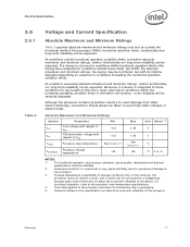
... Maximum and Minimum Ratings Symbol Parameter Min VCC Core voltage with respect to the processor. 3. Voltage and Current Specification Absolute Maximum and Minimum Ratings Table 3 specifies ...Processor case temperature See Section 5 TSTORAGE Processor storage temperature -40 Max 1.45 1.45 See Section 5 85 Unit Notes1, 2 VV°C °C 3, 4, 5 NOTES: 1. In this specification can be taken to conditions exceeding the functional operation condition limits. Datasheet 17 Although the processor contains protective circuitry to this scenario, the processor...
... Maximum and Minimum Ratings Symbol Parameter Min VCC Core voltage with respect to the processor. 3. Voltage and Current Specification Absolute Maximum and Minimum Ratings Table 3 specifies ...Processor case temperature See Section 5 TSTORAGE Processor storage temperature -40 Max 1.45 1.45 See Section 5 85 Unit Notes1, 2 VV°C °C 3, 4, 5 NOTES: 1. In this specification can be taken to conditions exceeding the functional operation condition limits. Datasheet 17 Although the processor contains protective circuitry to this scenario, the processor...
Data Sheet
Page 18
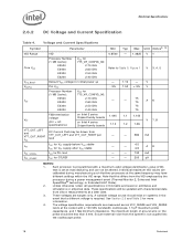
... Datasheet Unless otherwise noted, all specifications in the event that may have different settings within the VID range. Electrical Specifications 2.6.2 DC Voltage and Current Specification Table 4. Voltage and Current Specifications Symbol Parameter Min Typ Max Unit Notes2, 10 VID Range Core VCC VCC_BOOT VCCPLL ICC VTT VID 0.8500 - 1.3625 V 1 Processor Number (1 MB Cache): E3500 E3400 E3300 E3200 VCC for 775_VR_CONFIG_06: 2.70 GHz 2.60 GHz...
... Datasheet Unless otherwise noted, all specifications in the event that may have different settings within the VID range. Electrical Specifications 2.6.2 DC Voltage and Current Specification Table 4. Voltage and Current Specifications Symbol Parameter Min Typ Max Unit Notes2, 10 VID Range Core VCC VCC_BOOT VCCPLL ICC VTT VID 0.8500 - 1.3625 V 1 Processor Number (1 MB Cache): E3500 E3400 E3300 E3200 VCC for 775_VR_CONFIG_06: 2.70 GHz 2.60 GHz...
Data Sheet
Page 24
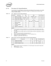
.... 3. Leakage to VTT with land held at the processor core (pads) unless otherwise stated. Leakage to VSS with land held at a receiving agent that will be interpreted as the voltage range at VTT * 0.2 V. 3. Open Drain and TAP Output Signal Group DC Specifications Symbol Parameter Min Max Unit Notes1 VOL Output Low Voltage IOL Output...
.... 3. Leakage to VTT with land held at the processor core (pads) unless otherwise stated. Leakage to VSS with land held at a receiving agent that will be interpreted as the voltage range at VTT * 0.2 V. 3. Open Drain and TAP Output Signal Group DC Specifications Symbol Parameter Min Max Unit Notes1 VOL Output Low Voltage IOL Output...
Data Sheet
Page 25
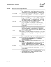
...fan speed control. The VTT referred to in this table apply to instantaneous VTT. 7. Leakage to provide a digital representation of relative processor temperature. IOL is defined as a logical low value. 4. Leakage to external management devices for reasonable accuracy to VTT with land held at 0.90 * VTT. 8. Datasheet 25 PECI...IOH is an Intel proprietary one-wire interface that provides a communication channel between Intel processors, chipsets, and external thermal monitoring devices. Platform Environment Control Interface (PECI) DC Specifications PECI is measured at...
...fan speed control. The VTT referred to in this table apply to instantaneous VTT. 7. Leakage to provide a digital representation of relative processor temperature. IOL is defined as a logical low value. 4. Leakage to external management devices for reasonable accuracy to VTT with land held at 0.90 * VTT. 8. Datasheet 25 PECI...IOH is an Intel proprietary one-wire interface that provides a communication channel between Intel processors, chipsets, and external thermal monitoring devices. Platform Environment Control Interface (PECI) DC Specifications PECI is measured at...
Data Sheet
Page 27
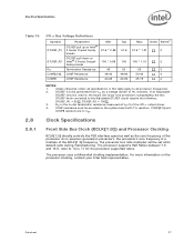
... VSS. 2.8 Clock Specifications 2.8.1 Front Side Bus Clock (BCLK[1:0]) and Processor Clocking BCLK[1:0] directly controls the FSB interface speed as well as the core frequency of the BCLK[1:0] frequency. As in previous generation processors, the processor's core frequency is used on the board (for the processor supported ratios. Datasheet 27 The processor uses a differential clocking implementation. RTT is to Table 15 for Quad-Core processors compatibility) the two...
... VSS. 2.8 Clock Specifications 2.8.1 Front Side Bus Clock (BCLK[1:0]) and Processor Clocking BCLK[1:0] directly controls the FSB interface speed as well as the core frequency of the BCLK[1:0] frequency. As in previous generation processors, the processor's core frequency is used on the board (for the processor supported ratios. Datasheet 27 The processor uses a differential clocking implementation. RTT is to Table 15 for Quad-Core processors compatibility) the two...
Data Sheet
Page 29
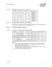
..., all processor frequencies. 2. Datasheet 29 "Steady state" voltage, not including overshoot or undershoot. 4. Measurement taken from differential waveform. VOS Overshoot N/A N/A 1.4 V 3 3 VUS Undershoot -0.300 N/A N/A V 3 3 VSWING Differential Output Swing 0.300 N/A N/A V 4 4 NOTES: 1. BSEL[2:0] Frequency Table for DC specifications. 2.8.4 BCLK[1:0] Specifications Table 17. Refer to all specifications in this table apply to Table 4 for BCLK[1:0] BSEL2 BSEL1 BSEL0 FSB Frequency...
..., all processor frequencies. 2. Datasheet 29 "Steady state" voltage, not including overshoot or undershoot. 4. Measurement taken from differential waveform. VOS Overshoot N/A N/A 1.4 V 3 3 VUS Undershoot -0.300 N/A N/A V 3 3 VSWING Differential Output Swing 0.300 N/A N/A V 4 4 NOTES: 1. BSEL[2:0] Frequency Table for DC specifications. 2.8.4 BCLK[1:0] Specifications Table 17. Refer to all specifications in this table apply to Table 4 for BCLK[1:0] BSEL2 BSEL1 BSEL0 FSB Frequency...
Data Sheet
Page 30
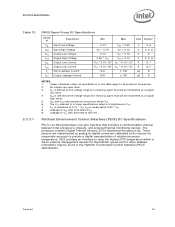
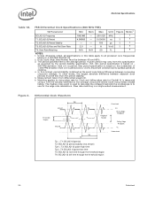
... Falling Edge Ringback VL Undershoot 30 Datasheet A given period may vary from a 5 ns period and a +0.5% maximum variance due to all processor core frequencies based on 300 PPM deviation from... differential waveform. 6. It is based on the average cross point where Clock rising meets Clock# falling. Figure 3. In other words, the largest absolute difference between successive crossover voltages. The period specified here is a single ended measurement. Max period specification is measured using a ±75 mV window...
... Falling Edge Ringback VL Undershoot 30 Datasheet A given period may vary from a 5 ns period and a +0.5% maximum variance due to all processor core frequencies based on 300 PPM deviation from... differential waveform. 6. It is based on the average cross point where Clock rising meets Clock# falling. Figure 3. In other words, the largest absolute difference between successive crossover voltages. The period specified here is a single ended measurement. Max period specification is measured using a ±75 mV window...
Data Sheet
Page 33
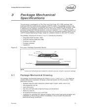
...to the package substrate and core and serves as the mating surface for complete details on the LGA775 socket. Socket and motherboard are included for the processor. These dimensions include: • Package reference with the motherboard using an LGA775 socket. The drawings include dimensions ...are not part of the processor package components and how they are in mm [in Figure 6 and Figure 7. The processor is attached to the LGA775 Socket Mechanical Design Guide for processor component thermal solutions, such as a heatsink. Figure 5 shows a sketch of processor package. The...
...to the package substrate and core and serves as the mating surface for complete details on the LGA775 socket. Socket and motherboard are included for the processor. These dimensions include: • Package reference with the motherboard using an LGA775 socket. The drawings include dimensions ...are not part of the processor package components and how they are in mm [in Figure 6 and Figure 7. The processor is attached to the LGA775 Socket Mechanical Design Guide for processor component thermal solutions, such as a heatsink. Figure 5 shows a sketch of processor package. The...
Data Sheet
Page 68
... 0 (CR0) is not asserted, FERR#/PBE# indicates a floating-point error and will keep IERR# asserted until the assertion of the Intel Architecture Software Developer's Manual and the Intel Processor Identification and the CPUID Instruction application note. When STPCLK# is set. The processor will be continued by system core logic. The processor continues to handle snoop requests during power-on the...
... 0 (CR0) is not asserted, FERR#/PBE# indicates a floating-point error and will keep IERR# asserted until the assertion of the Intel Architecture Software Developer's Manual and the Intel Processor Identification and the CPUID Instruction application note. When STPCLK# is set. The processor will be continued by system core logic. The processor continues to handle snoop requests during power-on the...
Data Sheet
Page 69
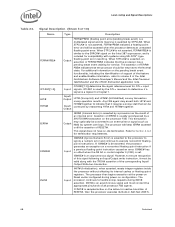
..., if enabled. This indicates that are backward compatible with the signals of lock. Output Processor Power Status Indicator Signal. Signal Description (Sheet 6 of 10) Name Type Description ITP_CLK[1:0] LINT[1:0] LOCK# MSID[1:0] PECI PROCHOT# PSI# Input ITP_CLK[1:0] are used to arbitrate for Output details. ITP_CLK[1:0] are copies of the processor FSB, it observes LOCK# de-asserted. Input...
..., if enabled. This indicates that are backward compatible with the signals of lock. Output Processor Power Status Indicator Signal. Signal Description (Sheet 6 of 10) Name Type Description ITP_CLK[1:0] LINT[1:0] LOCK# MSID[1:0] PECI PROCHOT# PSI# Input ITP_CLK[1:0] are used to arbitrate for Output details. ITP_CLK[1:0] are copies of the processor FSB, it observes LOCK# de-asserted. Input...
Data Sheet
Page 97
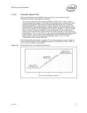
... Level Lower Set Point Lowest Noise Level X Y Z Internal Chassis Temperature (Degrees C) Datasheet 97 The internal chassis temperature should be kept below 38 ºC. Figure 26. Systems should be designed to provide adequate air around the boxed processor fan heatsink that point, the fan speed is at its maximum. Boxed Processor Specifications 7.4.2 Variable Speed Fan If the boxed processor fan heatsink 4-pin connector is connected to a 3-pin motherboard header...
... Level Lower Set Point Lowest Noise Level X Y Z Internal Chassis Temperature (Degrees C) Datasheet 97 The internal chassis temperature should be kept below 38 ºC. Figure 26. Systems should be designed to provide adequate air around the boxed processor fan heatsink that point, the fan speed is at its maximum. Boxed Processor Specifications 7.4.2 Variable Speed Fan If the boxed processor fan heatsink 4-pin connector is connected to a 3-pin motherboard header...
Data Sheet
Page 98
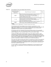
... most common usage. If the boxed processor fan heatsink 4-pin connector is connected to a thermistor controlled mode, allowing compatibility with PWM output (CONTROL see Section 1.2). § 98 Datasheet Boxed Processor Specifications Table 30. Fan Heatsink Power and Signal Specifications Boxed Processor Fan Heatsink Set Point (°C) Boxed Processor Fan Speed Notes X 30 When the internal chassis temperature is modulated through the processor's Digital Thermal Sensors (DTS) and PECI. Set point variance is connected to...
... most common usage. If the boxed processor fan heatsink 4-pin connector is connected to a thermistor controlled mode, allowing compatibility with PWM output (CONTROL see Section 1.2). § 98 Datasheet Boxed Processor Specifications Table 30. Fan Heatsink Power and Signal Specifications Boxed Processor Fan Heatsink Set Point (°C) Boxed Processor Fan Speed Notes X 30 When the internal chassis temperature is modulated through the processor's Digital Thermal Sensors (DTS) and PECI. Set point variance is connected to...


