
Data Sheet
Page 2
... not rely on changes in any particular feature. Intel processor numbers are trademarks of Intel Corporation in the U.S. See the Processor Spec Finder at http://processorfinder.intel.com or contact your Intel representative for more information including details on which may... known as the property of this processor support Thermal Monitor 2, Enhanced HALT State and Enhanced Intel SpeedStep® Technology. Intel, Pentium, Celeron, Intel Core, Intel SpeedStep, and the Intel logo are not a measure of this processor support Enhanced Intel SpeedStep® Technology. All rights ...
... not rely on changes in any particular feature. Intel processor numbers are trademarks of Intel Corporation in the U.S. See the Processor Spec Finder at http://processorfinder.intel.com or contact your Intel representative for more information including details on which may... known as the property of this processor support Thermal Monitor 2, Enhanced HALT State and Enhanced Intel SpeedStep® Technology. Intel, Pentium, Celeron, Intel Core, Intel SpeedStep, and the Intel logo are not a measure of this processor support Enhanced Intel SpeedStep® Technology. All rights ...
Data Sheet
Page 3
... 2.6.4 Die Voltage Validation 21 2.7 Signaling Specifications 21 2.7.1 FSB Signal Groups 22 2.7.2 CMOS and Open Drain Signals 23 2.7.3 Processor DC Specifications 24 2.7.3.1 Platform Environment Control Interface (PECI) DC Specifications..... 25 2.7.3.2 GTL+ Front Side Bus Specifications 26 2.8 ...Clock Specifications 27 2.8.1 Front Side Bus Clock (BCLK[1:0]) and Processor Clocking 27 2.8.2 FSB Frequency Select Signals (BSEL[2:0 28 2.8.3 Phase Lock Loop (PLL) and Filter 29 2.8.4 BCLK[1:0] Specifications 29 ...
... 2.6.4 Die Voltage Validation 21 2.7 Signaling Specifications 21 2.7.1 FSB Signal Groups 22 2.7.2 CMOS and Open Drain Signals 23 2.7.3 Processor DC Specifications 24 2.7.3.1 Platform Environment Control Interface (PECI) DC Specifications..... 25 2.7.3.2 GTL+ Front Side Bus Specifications 26 2.8 ...Clock Specifications 27 2.8.1 Front Side Bus Clock (BCLK[1:0]) and Processor Clocking 27 2.8.2 FSB Frequency Select Signals (BSEL[2:0 28 2.8.3 Phase Lock Loop (PLL) and Filter 29 2.8.4 BCLK[1:0] Specifications 29 ...
Data Sheet
Page 4
... 89 6.2.6 Deep Sleep State 89 6.2.7 Deeper Sleep State 90 6.2.8 Enhanced Intel SpeedStep® Technology 90 6.3 Processor Power Status Indicator (PSI) Signal 90 7 Boxed Processor Specifications 91 7.1 Introduction ...91 7.2 Mechanical Specifications 92 7.2.1 Boxed Processor Cooling Solution Dimensions 92 7.2.2 Boxed Processor Fan Heatsink Weight 93 7.2.3 Boxed Processor Retention Mechanism and Heatsink Attach Clip Assembly .....93 7.3 Electrical Requirements 93...
... 89 6.2.6 Deep Sleep State 89 6.2.7 Deeper Sleep State 90 6.2.8 Enhanced Intel SpeedStep® Technology 90 6.3 Processor Power Status Indicator (PSI) Signal 90 7 Boxed Processor Specifications 91 7.1 Introduction ...91 7.2 Mechanical Specifications 92 7.2.1 Boxed Processor Cooling Solution Dimensions 92 7.2.2 Boxed Processor Fan Heatsink Weight 93 7.2.3 Boxed Processor Retention Mechanism and Heatsink Attach Clip Assembly .....93 7.3 Electrical Requirements 93...
Data Sheet
Page 5
... 21 Overall View Space Requirements for Differential Clock Waveforms 31 5 Processor Package Assembly Sketch 33 6 Processor Package Drawing Sheet 1 of 3 34 7 Processor Package Drawing Sheet 2 of 3 35 8 Processor Package Drawing Sheet 3 of 3 36 9 Intel® Celeron® Processor E3000 Series Top-Side Markings Example 38 10 Processor Land Coordinates and Quadrants, Top View 39 11 land-out...
... 21 Overall View Space Requirements for Differential Clock Waveforms 31 5 Processor Package Assembly Sketch 33 6 Processor Package Drawing Sheet 1 of 3 34 7 Processor Package Drawing Sheet 2 of 3 35 8 Processor Package Drawing Sheet 3 of 3 36 9 Intel® Celeron® Processor E3000 Series Top-Side Markings Example 38 10 Processor Land Coordinates and Quadrants, Top View 39 11 land-out...

Data Sheet
Page 6
...1 References ...11 2 Voltage Identification Definition 15 3 Absolute Maximum and Minimum Ratings 17 4 Voltage and Current Specifications 18 5 Processor VCC Static and Transient Tolerance 19 6 VCC Overshoot Specifications 20 7 FSB Signal Groups ...22 8 Signal Characteristics 23 9 Signal... Side Bus Differential BCLK Specifications 29 18 FSB Differential Clock Specifications (800 MHz FSB 30 19 Processor Loading Specifications 37 20 Package Handling Guidelines 37 21 Processor Materials 38 22 Alphabetical Land Assignments 44 23 Numerical Land Assignment 54 24 Signal Description...64 25...
...1 References ...11 2 Voltage Identification Definition 15 3 Absolute Maximum and Minimum Ratings 17 4 Voltage and Current Specifications 18 5 Processor VCC Static and Transient Tolerance 19 6 VCC Overshoot Specifications 20 7 FSB Signal Groups ...22 8 Signal Characteristics 23 9 Signal... Side Bus Differential BCLK Specifications 29 18 FSB Differential Clock Specifications (800 MHz FSB 30 19 Processor Loading Specifications 37 20 Package Handling Guidelines 37 21 Processor Materials 38 22 Alphabetical Land Assignments 44 23 Numerical Land Assignment 54 24 Signal Description...64 25...
Data Sheet
Page 7
..., image processing, video content creation, speech, 3D, CAD, games, multimedia, and multitasking user environments. Intel® 64 architecture enables the processor to execute operating systems and applications written to take advantage of -order execution • Enhanced branch prediction ...hit rate on load/store operations • 775-land Package The Intel® Celeron® processor E3000 series is based on the Enhanced Intel® Core™ microarchitecture. The processor, supporting Enhanced Intel Speedstep® technology, allows tradeoffs to be marked as executable ...
..., image processing, video content creation, speech, 3D, CAD, games, multimedia, and multitasking user environments. Intel® 64 architecture enables the processor to execute operating systems and applications written to take advantage of -order execution • Enhanced branch prediction ...hit rate on load/store operations • 775-land Package The Intel® Celeron® processor E3000 series is based on the Enhanced Intel® Core™ microarchitecture. The processor, supporting Enhanced Intel Speedstep® technology, allows tradeoffs to be marked as executable ...

Data Sheet
Page 8
Revision History Revision Number 001 002 003 Description • Initial release • Intel® Celeron® processor E3400 • Changed the processor numbering from Intel Celeron processor E3x00 series to Intel Celeron processor E3000 series. • Intel® Celeron® processor E3500 Revision Date August 2009 January 2010 August 2010 § § 8 Datasheet
Revision History Revision Number 001 002 003 Description • Initial release • Intel® Celeron® processor E3400 • Changed the processor numbering from Intel Celeron processor E3x00 series to Intel Celeron processor E3000 series. • Intel® Celeron® processor E3500 Revision Date August 2009 January 2010 August 2010 § § 8 Datasheet
Data Sheet
Page 9
... to improve performance by transferring data four times per bus clock and is referred to as "the processor." The processors are based on the Enhanced Intel® Core™ microarchitecture. hence, mechanical assembly may be completed from the top of the baseboard...address or data), the '#' symbol implies that significantly reduces latency to the Intel® Celeron® processor E3500, E3400, E3300, and E3200. In this document, unless otherwise specified, the Intel® Celeron® processor E3000 series refers to frequently used data. Along with the power efficiencies of...
... to improve performance by transferring data four times per bus clock and is referred to as "the processor." The processors are based on the Enhanced Intel® Core™ microarchitecture. hence, mechanical assembly may be completed from the top of the baseboard...address or data), the '#' symbol implies that significantly reduces latency to the Intel® Celeron® processor E3500, E3400, E3300, and E3200. In this document, unless otherwise specified, the Intel® Celeron® processor E3000 series refers to frequently used data. Along with the power efficiencies of...
Data Sheet
Page 10
...or worms that exploit buffer over the FSB. • Storage conditions-Refers to free air. An enhancement to Intel's IA-32 architecture, allowing the processor to execute operating systems and applications written to the operating system. If code attempts to run vulnerabilities and can...AC, system bus, signal quality, mechanical and thermal are explained here for clarification: • Intel® Celeron® processor E3000 series-Dual core processor in the FC-LGA8 package with the processor at the IHS surface. • Retention mechanism (RM)-Since the LGA775 socket does not include...
...or worms that exploit buffer over the FSB. • Storage conditions-Refers to free air. An enhancement to Intel's IA-32 architecture, allowing the processor to execute operating systems and applications written to the operating system. If code attempts to run vulnerabilities and can...AC, system bus, signal quality, mechanical and thermal are explained here for clarification: • Intel® Celeron® processor E3000 series-Dual core processor in the FC-LGA8 package with the processor at the IHS surface. • Retention mechanism (RM)-Since the LGA775 socket does not include...
Data Sheet
Page 11
... virtualization solutions and enables more robust hardware assisted virtualization solutions. References Document Intel® Celeron® Processor E3000 Series Specification Update Intel® Core™2 Duo Processor E8000 and E7000 Series, Intel® Pentium® Dual-Core Processor E6000 and E5000 Series, and Intel® Celeron Processor E3000 Series Thermal and Mechanical Design Guidelines Voltage Regulator-Down (VRD...
... virtualization solutions and enables more robust hardware assisted virtualization solutions. References Document Intel® Celeron® Processor E3000 Series Specification Update Intel® Core™2 Duo Processor E8000 and E7000 Series, Intel® Pentium® Dual-Core Processor E6000 and E5000 Series, and Intel® Celeron Processor E3000 Series Thermal and Mechanical Design Guidelines Voltage Regulator-Down (VRD...

Data Sheet
Page 13
... are required to a system ground plane. A separate supply must be provided on -chip power distribution. The processor VCC lands must be connected to filter high frequency content generated by the Voltage IDentification (VID) lands. Contact your Intel field representative for on the motherboard. Datasheet 13 Electrical Specifications 2 Electrical Specifications 2.1 2.2 2.2.1 2.2.2 This chapter describes...
... are required to a system ground plane. A separate supply must be provided on -chip power distribution. The processor VCC lands must be connected to filter high frequency content generated by the Voltage IDentification (VID) lands. Contact your Intel field representative for on the motherboard. Datasheet 13 Electrical Specifications 2 Electrical Specifications 2.1 2.2 2.2.1 2.2.2 This chapter describes...
Data Sheet
Page 14
... VRM or VRD used must be calibrated during a power management event (Thermal Monitor 2, Enhanced Intel SpeedStep® technology, or Extended HALT State). Refer to the value defined by the motherboard for the processor is included on the processor package. Transitions above the specified VID are included in this differs from the front side...
... VRM or VRD used must be calibrated during a power management event (Thermal Monitor 2, Enhanced Intel SpeedStep® technology, or Extended HALT State). Refer to the value defined by the motherboard for the processor is included on the processor package. Transitions above the specified VID are included in this differs from the front side...

Data Sheet
Page 16
... that leaving unused outputs unterminated may draw too much power and cause a potential VR issue. 16 Datasheet For example, a 130 W TDP processor installed in component malfunction or incompatibility with other signal (including each group: • TESTHI[1:0] • TESTHI[7:2] • TESTHI8/FC42 - ... Specifications 2.4 2.5 Reserved, Unused, and TESTHI Signals All RESERVED lands must be terminated on -die termination has been included by the processor to allow for system testability. In a system level design, on the motherboard. For details see Table 7 for details on GTL+...
... that leaving unused outputs unterminated may draw too much power and cause a potential VR issue. 16 Datasheet For example, a 130 W TDP processor installed in component malfunction or incompatibility with other signal (including each group: • TESTHI[1:0] • TESTHI[7:2] • TESTHI8/FC42 - ... Specifications 2.4 2.5 Reserved, Unused, and TESTHI Signals All RESERVED lands must be terminated on -die termination has been included by the processor to allow for system testability. In a system level design, on the motherboard. For details see Table 7 for details on GTL+...
Data Sheet
Page 17
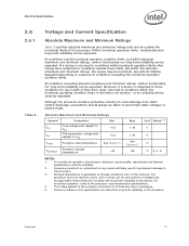
... likely result in permanent damage to this scenario, the processor must be severely degraded. Failure to adhere to the processor. 3. This rating applies to the processor and does not include any length of time then, when... precautions should always be expected. At conditions outside the functional limits of the processor. Electrical Specifications 2.6 2.6.1 Table 3. Although the processor contains protective circuitry to VSS -0.3 TCASE Processor case temperature See Section 5 TSTORAGE Processor storage temperature -40 Max 1.45 1.45 See Section 5 85 Unit Notes1,...
... likely result in permanent damage to this scenario, the processor must be severely degraded. Failure to adhere to the processor. 3. This rating applies to the processor and does not include any length of time then, when... precautions should always be expected. At conditions outside the functional limits of the processor. Electrical Specifications 2.6 2.6.1 Table 3. Although the processor contains protective circuitry to VSS -0.3 TCASE Processor case temperature See Section 5 TSTORAGE Processor storage temperature -40 Max 1.45 1.45 See Section 5 85 Unit Notes1,...
Data Sheet
Page 18
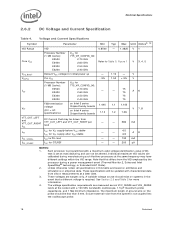
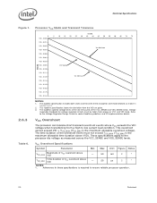
...Specifications Symbol Parameter Min Typ Max Unit Notes2, 10 VID Range Core VCC VCC_BOOT VCCPLL ICC VTT VID 0.8500 - 1.3625 V 1 Processor Number (1 MB Cache): E3500 E3400 E3300 E3200 VCC for 775_VR_CONFIG_06: 2.70 GHz 2.60 GHz 2.50 GHz 2.40 GHz Refer to Table 5, Figure 1 V 3, 4, ... 2.60 GHz E3300 2.50 GHz E3200 2.40 GHz - - 5% - 1.10 1.50 - + 5% 75 - 75 75 75 V V A6 FSB termination voltage (DC + AC specifications) on Intel 3 series Chipset family boards on the probe should exist on estimates and simulations or empirical data. Each processor is required. ...
...Specifications Symbol Parameter Min Typ Max Unit Notes2, 10 VID Range Core VCC VCC_BOOT VCCPLL ICC VTT VID 0.8500 - 1.3625 V 1 Processor Number (1 MB Cache): E3500 E3400 E3300 E3200 VCC for 775_VR_CONFIG_06: 2.70 GHz 2.60 GHz 2.50 GHz 2.40 GHz Refer to Table 5, Figure 1 V 3, 4, ... 2.60 GHz E3300 2.50 GHz E3200 2.40 GHz - - 5% - 1.10 1.50 - + 5% 75 - 75 75 75 V V A6 FSB termination voltage (DC + AC specifications) on Intel 3 series Chipset family boards on the probe should exist on estimates and simulations or empirical data. Each processor is required. ...
Data Sheet
Page 19
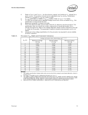
... to Figure 1 for socket loadline guidelines and VR implementation details. 4. Refer to the Voltage Regulator Design Guide to ensure reliable processor operation. This is based on -board termination (RTT), through the signal line. ICC_MAX specification is the maximum total current drawn ...-0.173 NOTES: 1. Baseboard bandwidth is required to determine the total ITT drawn by only the processor. Datasheet 19 Adherence to ensure reliable processor operation. Processor VCC Static and Transient Tolerance Voltage Deviation from the VTT plane by the system. Voltage regulation ...
... to Figure 1 for socket loadline guidelines and VR implementation details. 4. Refer to the Voltage Regulator Design Guide to ensure reliable processor operation. This is based on -board termination (RTT), through the signal line. ICC_MAX specification is the maximum total current drawn ...-0.173 NOTES: 1. Baseboard bandwidth is required to determine the total ITT drawn by only the processor. Datasheet 19 Adherence to ensure reliable processor operation. Processor VCC Static and Transient Tolerance Voltage Deviation from the VTT plane by the system. Voltage regulation ...
Data Sheet
Page 20
...181;s 2 1 NOTES: 1. The loadlines specify voltage limits at the die measured at the VCC_SENSE and VSS_SENSE lands. VCC Overshoot The processor can tolerate short transient overshoot events where VCC exceeds the VID voltage when transitioning from the VID set point. 3. Adherence to low current...VOS_MAX Magnitude of VCC overshoot above VID - 50 mV 2 1 TOS_MAX Time duration of the overshoot event must be taken from processor VCC and VSS lands. Voltage regulation feedback for overshoot allowed as measured across the VCC_SENSE and VSS_SENSE lands. These specifications apply ...
...181;s 2 1 NOTES: 1. The loadlines specify voltage limits at the die measured at the VCC_SENSE and VSS_SENSE lands. VCC Overshoot The processor can tolerate short transient overshoot events where VCC exceeds the VID voltage when transitioning from the VID set point. 3. Adherence to low current...VOS_MAX Magnitude of VCC overshoot above VID - 50 mV 2 1 TOS_MAX Time duration of the overshoot event must be taken from processor VCC and VSS lands. Voltage regulation feedback for overshoot allowed as measured across the VCC_SENSE and VSS_SENSE lands. These specifications apply ...

Data Sheet
Page 21
... Specifications Figure 2. VOS is measured time duration above VID 2.6.4 2.7 NOTES: 1. Die Voltage Validation Overshoot events on the motherboard for each processor (and chipset), separate VCC and VTT supplies are terminated to determine if a signal is a logical 0 or a logical 1. This technology...< 10 ns in Table 6 when measured across the VCC_SENSE and VSS_SENSE lands. Intel chipsets will also provide on-die termination, thus eliminating the need to terminate the bus on processor must meet the specifications in duration may be taken with a bandwidth limited oscilloscope ...
... Specifications Figure 2. VOS is measured time duration above VID 2.6.4 2.7 NOTES: 1. Die Voltage Validation Overshoot events on the motherboard for each processor (and chipset), separate VCC and VTT supplies are terminated to determine if a signal is a logical 0 or a logical 1. This technology...< 10 ns in Table 6 when measured across the VCC_SENSE and VSS_SENSE lands. Intel chipsets will also provide on-die termination, thus eliminating the need to terminate the bus on processor must meet the specifications in duration may be taken with a bandwidth limited oscilloscope ...

Data Sheet
Page 22
... to the GTL+ input group as well as the GTL+ I /O Synchronous to the GTL+ output group as well as the GTL+ I/O group when receiving. In processor systems where no connects. 22 Datasheet One set is for signal descriptions. 2. FSB Signal Groups Signal Group Type Signals1 GTL+ Common Clock Input GTL+ Common...
... to the GTL+ input group as well as the GTL+ I /O Synchronous to the GTL+ output group as well as the GTL+ I/O group when receiving. In processor systems where no connects. 22 Datasheet One set is for signal descriptions. 2. FSB Signal Groups Signal Group Type Signals1 GTL+ Common Clock Input GTL+ Common...

Data Sheet
Page 23
...[3:0]#, LOCK#, REQ[4:0]#, RS[2:0]#, TRDY# A20M#, LINT0/INTR, LINT1/NMI, IGNNE#, INIT#, PROCHOT#, PWRGOOD1, SMI#, STPCLK#, TCK1, TDI1, TMS1, TRST#1 NOTE: 1. All of RESET# defines the processor configuration options. Electrical Specifications . Signals that do not have RTT, nor are required to be asserted/deasserted for at least eight BCLKs for the...
...[3:0]#, LOCK#, REQ[4:0]#, RS[2:0]#, TRDY# A20M#, LINT0/INTR, LINT1/NMI, IGNNE#, INIT#, PROCHOT#, PWRGOOD1, SMI#, STPCLK#, TCK1, TDI1, TMS1, TRST#1 NOTE: 1. All of RESET# defines the processor configuration options. Electrical Specifications . Signals that do not have RTT, nor are required to be asserted/deasserted for at least eight BCLKs for the...


