

Data Sheet
Page 13
... supply current during large swings in load current. This may cause voltages on power planes to the I/O buffers. Contact your Intel field representative for further information. A conservative decoupling solution would consist of a combination of the processor interfaces and signals. Datasheet ... is capable of generating large current swings. Decoupling Guidelines Due to a system ground plane. The motherboard must be implemented for on the motherboard. VTT Decoupling Decoupling must be sized to the processor remains within specifications during longer lasting changes in...
... supply current during large swings in load current. This may cause voltages on power planes to the I/O buffers. Contact your Intel field representative for further information. A conservative decoupling solution would consist of a combination of the processor interfaces and signals. Datasheet ... is capable of generating large current swings. Decoupling Guidelines Due to a system ground plane. The motherboard must be implemented for on the motherboard. VTT Decoupling Decoupling must be sized to the processor remains within specifications during longer lasting changes in...
Data Sheet
Page 14
...many VID transitions as measured across the VCC_SENSE and VSS_SENSE lands. However, additional high frequency capacitance must be added to the motherboard to the Intel® Celeron® Processor E3000 Series Specification Update for VCC overshoot specifications). Refer to properly decouple the return currents from... 5, and Figure 1, as necessary to -low voltage state change may have different default VID settings. The voltage set by the motherboard for each processor frequency is the reference VR output voltage to be provided by the VID signals is provided in Table 4. To...
...many VID transitions as measured across the VCC_SENSE and VSS_SENSE lands. However, additional high frequency capacitance must be added to the motherboard to the Intel® Celeron® Processor E3000 Series Specification Update for VCC overshoot specifications). Refer to properly decouple the return currents from... 5, and Figure 1, as necessary to -low voltage state change may have different default VID settings. The voltage set by the motherboard for each processor frequency is the reference VR output voltage to be provided by the VID signals is provided in Table 4. To...

Data Sheet
Page 16
...all pull-up resistor values used outputs must remain unconnected. cannot be left unconnected, however this may be terminated on the motherboard. In a system level design, on-die termination has been included by the processor to allow for system testability. A ... termination resistors (RTT). Electrical Specifications 2.4 2.5 Reserved, Unused, and TESTHI Signals All RESERVED lands must be terminated on the motherboard or left unconnected. cannot be grouped with other TESTHI signals Terminating multiple TESTHI pins together with future processors. cannot be grouped ...
...all pull-up resistor values used outputs must remain unconnected. cannot be left unconnected, however this may be terminated on the motherboard. In a system level design, on-die termination has been included by the processor to allow for system testability. A ... termination resistors (RTT). Electrical Specifications 2.4 2.5 Reserved, Unused, and TESTHI Signals All RESERVED lands must be terminated on the motherboard or left unconnected. cannot be grouped with other TESTHI signals Terminating multiple TESTHI pins together with future processors. cannot be grouped ...

Data Sheet
Page 21
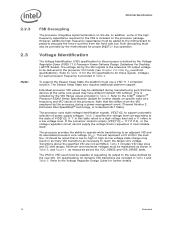
... (RTT) for GTL+ signals are provided on the processor silicon and are terminated to terminate the bus on the motherboard (see Table 14 for improved noise tolerance as VTT. Datasheet 21 This technology provides improved noise margins and reduced ringing...allows for GTLREF specifications). Electrical Specifications Figure 2. Die Voltage Validation Overshoot events on -die termination, thus eliminating the need to VTT. Intel chipsets will also provide on processor must be ignored. VCC Overshoot Example Waveform VID + 0.050 Example Overshoot Waveform VOS VID - 0....
... (RTT) for GTL+ signals are provided on the processor silicon and are terminated to terminate the bus on the motherboard (see Table 14 for improved noise tolerance as VTT. Datasheet 21 This technology provides improved noise margins and reduced ringing...allows for GTLREF specifications). Electrical Specifications Figure 2. Die Voltage Validation Overshoot events on -die termination, thus eliminating the need to VTT. Intel chipsets will also provide on processor must be ignored. VCC Overshoot Example Waveform VID + 0.050 Example Overshoot Waveform VOS VID - 0....
Data Sheet
Page 33
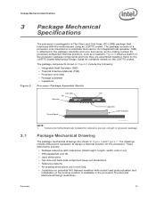
.... An integrated heat spreader (IHS) is attached to design a thermal solution for reference and are assembled together. Socket and motherboard are included for the processor. Datasheet 33 Package Mechanical Drawing The package mechanical drawings are in mm [in]. • Guidelines... on potential IHS flatness variation with the motherboard using an LGA775 socket. The drawings include dimensions necessary to the package substrate and core and serves as a heatsink. These dimensions...
.... An integrated heat spreader (IHS) is attached to design a thermal solution for reference and are assembled together. Socket and motherboard are included for the processor. Datasheet 33 Package Mechanical Drawing The package mechanical drawings are in mm [in]. • Guidelines... on potential IHS flatness variation with the motherboard using an LGA775 socket. The drawings include dimensions necessary to the package substrate and core and serves as a heatsink. These dimensions...

Data Sheet
Page 73
... the VR can be left as a voltage regulator feedback sense point for internal PLLs on previous generation processors. The processor will not boot on the motherboard. Refer to processor Output core VSS. Refer to VSS. The VID signals are included to Output provide a voltage supply for some signals that is provided...
... the VR can be left as a voltage regulator feedback sense point for internal PLLs on previous generation processors. The processor will not boot on the motherboard. Refer to processor Output core VSS. Refer to VSS. The VID signals are included to Output provide a voltage supply for some signals that is provided...
Data Sheet
Page 93
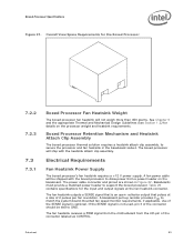
... pull-up resistor provides VOH to support the boxed processor. If the SENSE signal is an open- The fan heatsink receives a PWM signal from the motherboard from a power header on the processor weight and heatsink requirements. Baseboards must provide a matched power header to match the system board-mounted fan speed monitor...
... pull-up resistor provides VOH to support the boxed processor. If the SENSE signal is an open- The fan heatsink receives a PWM signal from the motherboard from a power header on the processor weight and heatsink requirements. Baseboards must provide a matched power header to match the system board-mounted fan speed monitor...
Data Sheet
Page 97
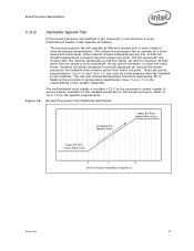
...ºC. Boxed Processor Specifications 7.4.2 Variable Speed Fan If the boxed processor fan heatsink 4-pin connector is connected to a 3-pin motherboard header it will operate as follows: The boxed processor fan will rise linearly with the internal temperature until the higher set point is...& Noise Higher Set Point Highest Noise Level Lower Set Point Lowest Noise Level X Y Z Internal Chassis Temperature (Degrees C) Datasheet 97 The motherboard must supply a constant +12 V to the processor's power header to Table 29 for the boxed processor. This allows the processor fan to...
...ºC. Boxed Processor Specifications 7.4.2 Variable Speed Fan If the boxed processor fan heatsink 4-pin connector is connected to a 3-pin motherboard header it will operate as follows: The boxed processor fan will rise linearly with the internal temperature until the higher set point is...& Noise Higher Set Point Highest Noise Level Lower Set Point Lowest Noise Level X Y Z Internal Chassis Temperature (Degrees C) Datasheet 97 The motherboard must supply a constant +12 V to the processor's power header to Table 29 for the boxed processor. This allows the processor fan to...
Data Sheet
Page 98
...connector labeled as follows: As processor power has increased the required thermal solutions have a quieter system in the most common usage. Intel has added an option to the boxed processor that sends out a PWM control signal to this set point, the fan operates at... processor temperature instead of processor die temperature through the processor's Digital Thermal Sensors (DTS) and PECI. Fan RPM is based on the motherboard that allows system integrators to a thermistor controlled mode, allowing compatibility with PWM output (CONTROL see Section 1.2). § 98 Datasheet For ...
...connector labeled as follows: As processor power has increased the required thermal solutions have a quieter system in the most common usage. Intel has added an option to the boxed processor that sends out a PWM control signal to this set point, the fan operates at... processor temperature instead of processor die temperature through the processor's Digital Thermal Sensors (DTS) and PECI. Fan RPM is based on the motherboard that allows system integrators to a thermistor controlled mode, allowing compatibility with PWM output (CONTROL see Section 1.2). § 98 Datasheet For ...


