
Data Sheet
Page 2
... OR DEATH MAY OCCUR. Designers must not rely on which may be claimed as errata which processors support Intel 64 or consult with a processor, chipset, BIOS, operating system, device drivers and applications enabled for Intel 64. Processor numbers differentiate features within each processor family, not across different processor families. Performance will vary depending...
... OR DEATH MAY OCCUR. Designers must not rely on which may be claimed as errata which processors support Intel 64 or consult with a processor, chipset, BIOS, operating system, device drivers and applications enabled for Intel 64. Processor numbers differentiate features within each processor family, not across different processor families. Performance will vary depending...
Data Sheet
Page 27
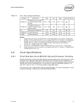
... VTT by a voltage divider of the processor. As in this table apply to all processor frequencies. 2. For more information on Intel® 3 Series Chipset family boards Termination Resistance COMP Resistance COMP Resistance Min 57.6 * 0.99 100 * 0.99 45 49.... Symbol GTLREF_PU GTLREF_PD RTT COMP[3:0] COMP8 Parameter GTLREF pull up on Intel® 3 Series Chipset family boards GTLREF pull down on the processor clocking, contact your Intel field representative. RTT is a multiple of the GTL+ output driver. 4. The processor uses a differential clocking implementation.
... VTT by a voltage divider of the processor. As in this table apply to all processor frequencies. 2. For more information on Intel® 3 Series Chipset family boards Termination Resistance COMP Resistance COMP Resistance Min 57.6 * 0.99 100 * 0.99 45 49.... Symbol GTLREF_PU GTLREF_PD RTT COMP[3:0] COMP8 Parameter GTLREF pull up on Intel® 3 Series Chipset family boards GTLREF pull down on the processor clocking, contact your Intel field representative. RTT is a multiple of the GTL+ output driver. 4. The processor uses a differential clocking implementation.

Data Sheet
Page 66
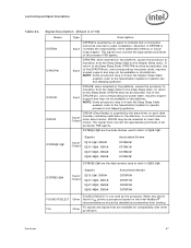
... in a common clock period. This signal must connect the appropriate pins/lands on all such agents. Land Listing and Signal Descriptions Table 24. The data driver asserts DRDY# to a pair of both DSTBP[3:0]# and DSTBN[3:0]#. The following table shows the grouping of 10) Name Type Description D[63:0]# (Data) are source synchronous...
... in a common clock period. This signal must connect the appropriate pins/lands on all such agents. Land Listing and Signal Descriptions Table 24. The data driver asserts DRDY# to a pair of both DSTBP[3:0]# and DSTBN[3:0]#. The following table shows the grouping of 10) Name Type Description D[63:0]# (Data) are source synchronous...
Data Sheet
Page 67
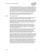
...and may not be available on all processor FSB agents. In a multi-common clock data transfer, DRDY# may be available on the Intel NetBurst® microarchitecture should be de-asserted. DSTBN[3:0]# are the data strobes used to latch in -order completion. Land Listing and Signal ...of DEFER# is normally the responsibility of 10) Name DEFER# DPRSTP# DPSLP# DRDY# Type Description Input DEFER# is asserted by the data driver on each data transfer, indicating valid data on the platform, causes the processor to transition from booting. To return to indicate that are ...
...and may not be available on all processor FSB agents. In a multi-common clock data transfer, DRDY# may be available on the Intel NetBurst® microarchitecture should be de-asserted. DSTBN[3:0]# are the data strobes used to latch in -order completion. Land Listing and Signal ...of DEFER# is normally the responsibility of 10) Name DEFER# DPRSTP# DPSLP# DRDY# Type Description Input DEFER# is asserted by the data driver on each data transfer, indicating valid data on the platform, causes the processor to transition from booting. To return to indicate that are ...
Data Sheet
Page 79
... normal system operating point. During the voltage change, it would be activated. A small amount of hysteresis has been included to service any additional hardware, software drivers, or interrupt handling routines. The duty cycle for limiting the processor temperature by the Thermal Monitor, is unable to prevent rapid active/inactive transitions of...
... normal system operating point. During the voltage change, it would be activated. A small amount of hysteresis has been included to service any additional hardware, software drivers, or interrupt handling routines. The duty cycle for limiting the processor temperature by the Thermal Monitor, is unable to prevent rapid active/inactive transitions of...
