
Product Guide
Page 3
... warn the user about how to prevent damage to hardware or loss of product features 2 Installing and Replacing Desktop Board Components: instructions on how to update the BIOS 4 Configuring for RAID Using Intel® Rapid Storage Technology: information about configuring your system for RAID A Error Messages and Indicators: information about board layout, component installation, BIOS update, and regulatory requirements for technically qualified personnel. It is intended for Intel® Desktop Board DP67BG. may not be supported without...
... warn the user about how to prevent damage to hardware or loss of product features 2 Installing and Replacing Desktop Board Components: instructions on how to update the BIOS 4 Configuring for RAID Using Intel® Rapid Storage Technology: information about configuring your system for RAID A Error Messages and Indicators: information about board layout, component installation, BIOS update, and regulatory requirements for technically qualified personnel. It is intended for Intel® Desktop Board DP67BG. may not be supported without...
Product Guide
Page 5
... Processor ...14 Main Memory...15 Intel® P67 Express Chipset 16 Audio Subsystem 16 LAN Subsystem 17 USB Support ...18 Serial ATA Support 18 Legacy I/O ...18 Expandability...18 BIOS ...19 Serial ATA Auto Configuration 19 PCI* and PCI Express* Auto Configuration 19 Security Passwords 19 Back to BIOS Button 20 Hardware Management 20 Hardware Monitoring and Fan Speed Control 20 Chassis Intrusion 21 Power Management 21 Software Support 21 ACPI 21 Hardware Support 21 Power Connectors 21 Fan Headers 22 LAN Wake Capabilities 22 Instantly Available PC Technology 22 Wake from USB...
... Processor ...14 Main Memory...15 Intel® P67 Express Chipset 16 Audio Subsystem 16 LAN Subsystem 17 USB Support ...18 Serial ATA Support 18 Legacy I/O ...18 Expandability...18 BIOS ...19 Serial ATA Auto Configuration 19 PCI* and PCI Express* Auto Configuration 19 Security Passwords 19 Back to BIOS Button 20 Hardware Management 20 Hardware Monitoring and Fan Speed Control 20 Chassis Intrusion 21 Power Management 21 Software Support 21 ACPI 21 Hardware Support 21 Power Connectors 21 Fan Headers 22 LAN Wake Capabilities 22 Instantly Available PC Technology 22 Wake from USB...

Product Guide
Page 6
...Linked PCI Express Graphics Cards 44 Connecting the Serial ATA (SATA) Cables 46 Connecting to the Internal Headers 47 S/PDIF Header 48 IEEE 1394a Header 48 Front Panel Intel HD Audio Header 48 Alternate Front Panel Power LED Header 49 Consumer IR (CIR) Headers 49 USB 2.0 Headers 50 Front Panel Header 51 Chassis Intrusion Header 51 Connecting to the Audio System 52 Connecting Chassis Fan and Power Supply Cables 53 Connecting Chassis Fan Cables 53 Connecting Power Supply Cables 54 Setting the BIOS Configuration Jumper 55 Clearing Passwords 56 Replacing the Battery 57 Installing...
...Linked PCI Express Graphics Cards 44 Connecting the Serial ATA (SATA) Cables 46 Connecting to the Internal Headers 47 S/PDIF Header 48 IEEE 1394a Header 48 Front Panel Intel HD Audio Header 48 Alternate Front Panel Power LED Header 49 Consumer IR (CIR) Headers 49 USB 2.0 Headers 50 Front Panel Header 51 Chassis Intrusion Header 51 Connecting to the Audio System 52 Connecting Chassis Fan and Power Supply Cables 53 Connecting Chassis Fan Cables 53 Connecting Power Supply Cables 54 Setting the BIOS Configuration Jumper 55 Clearing Passwords 56 Replacing the Battery 57 Installing...
Product Guide
Page 7
... Figures 1. Intel Desktop Board DP67BG Components 12 2. Onboard Power and Reset Buttons 24 5. Lift the Load Plate 34 11. Connecting the Processor Fan Heat Sink Power Cable to BIOS Button 20 4. Removing a PCI Express x16 Graphics Card 44 22. Connecting the Serial ATA Cables 46 24. Location of the Diagnostic LEDs 27 7. Example Dual Channel Memory Configuration with Three DIMMs 39 18. Installing a DIMM 41 20. Unlatch the Socket Lever 33 10. Remove the Processor from the Protective Cover 35 12. Example Dual Channel Memory Configuration with Two...
... Figures 1. Intel Desktop Board DP67BG Components 12 2. Onboard Power and Reset Buttons 24 5. Lift the Load Plate 34 11. Connecting the Processor Fan Heat Sink Power Cable to BIOS Button 20 4. Removing a PCI Express x16 Graphics Card 44 22. Connecting the Serial ATA Cables 46 24. Location of the Diagnostic LEDs 27 7. Example Dual Channel Memory Configuration with Three DIMMs 39 18. Installing a DIMM 41 20. Unlatch the Socket Lever 33 10. Remove the Processor from the Protective Cover 35 12. Example Dual Channel Memory Configuration with Two...
Product Guide
Page 8
... 83 22. Location of the Chassis Fan Headers 53 27. Intel Desktop Board DP67BG Components 13 3. Chassis Intrusion Header Signal Names 51 15. BIOS Beep Codes 71 17. BIOS Error Messages 72 19. Connecting Power Supply Cables 54 28. Installing the WiFi/Bluetooth Module 64 31. Diagnostic LEDs 26 6. Removing the Battery 62 30. Front Panel Intel HD Audio Header Signal Names 48 9. Back Panel CIR Header Emitter (Output) Header Signal Names 50 12. Front-panel Power LED Blink Codes 71 18. LAN Connector LEDs 17 5. Feature...
... 83 22. Location of the Chassis Fan Headers 53 27. Intel Desktop Board DP67BG Components 13 3. Chassis Intrusion Header Signal Names 51 15. BIOS Beep Codes 71 17. BIOS Error Messages 72 19. Connecting Power Supply Cables 54 28. Installing the WiFi/Bluetooth Module 64 31. Diagnostic LEDs 26 6. Removing the Battery 62 30. Front Panel Intel HD Audio Header Signal Names 48 9. Back Panel CIR Header Emitter (Output) Header Signal Names 50 12. Front-panel Power LED Blink Codes 71 18. LAN Connector LEDs 17 5. Feature...
Product Guide
Page 10
... back panel connector with integrated status LEDs • Intel® Platform Innovation Framework for extensible firmware interface • 32 Mb symmetrical flash memory device • Support for SMBIOS • Intel® Express BIOS Update • Support for Advanced Configuration and Power Interface (ACPI) • Suspend to RAM (STR) • Wake on USB, PCI, PCI Express, LAN, CIR, and front panel • ENERGY STAR* capable Hardware and thermal management based on: ― Nuvoton W83677HG-I legacy I/O controller ― Four fan...
... back panel connector with integrated status LEDs • Intel® Platform Innovation Framework for extensible firmware interface • 32 Mb symmetrical flash memory device • Support for SMBIOS • Intel® Express BIOS Update • Support for Advanced Configuration and Power Interface (ACPI) • Suspend to RAM (STR) • Wake on USB, PCI, PCI Express, LAN, CIR, and front panel • ENERGY STAR* capable Hardware and thermal management based on: ― Nuvoton W83677HG-I legacy I/O controller ― Four fan...
Product Guide
Page 19
... you must enter either password to run the BIOS Setup program after installing a Serial ATA. Setup options are then available for booting the computer, with the following the instructions in your computer. Related Links: For instructions on resetting the password, go to view and change all Setup options. Serial ATA Auto Configuration If you install a PCI/PCI Express add-in card in Chapter 3 starting on page 56. 19 PCI* and PCI Express* Auto Configuration If you install a Serial ATA device (such as a hard drive) in...
... you must enter either password to run the BIOS Setup program after installing a Serial ATA. Setup options are then available for booting the computer, with the following the instructions in your computer. Related Links: For instructions on resetting the password, go to view and change all Setup options. Serial ATA Auto Configuration If you install a PCI/PCI Express add-in card in Chapter 3 starting on page 56. 19 PCI* and PCI Express* Auto Configuration If you install a Serial ATA device (such as a hard drive) in...
Product Guide
Page 21
... monitored closed-loop fan control, for the location of the chassis intrusion header. See Figure 24 for the location of the power connectors. 21 The Desktop Board has three power connectors. The security feature uses a mechanical switch on the chassis that detects if the chassis cover has been removed. See Figure 27 on page 54 for all non-standby voltages. Hardware Support Power Connectors ATX12V-compliant power supplies can be connected to RAM) • Wake from USB • Power...
... monitored closed-loop fan control, for the location of the chassis intrusion header. See Figure 24 for the location of the power connectors. 21 The Desktop Board has three power connectors. The security feature uses a mechanical switch on the chassis that detects if the chassis cover has been removed. See Figure 27 on page 54 for all non-standby voltages. Hardware Support Power Connectors ATX12V-compliant power supplies can be connected to RAM) • Wake from USB • Power...
Product Guide
Page 44
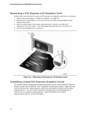
...the card from a connector: 1. Pull the card straight up to connect the two graphics cards together. You can use two identical SLI-ready graphics cards that are NVIDIA certified and the latest graphics driver. Intel Desktop Board DP67BG Product Guide Removing a PCI Express x16 Graphics Card Follow these instructions to remove a PCI Express x16 graphics card from the connector (C). 4. Removing a PCI Express x16 Graphics Card Installing Linked PCI Express Graphics Cards The Desktop Board supports technology that secures the card's metal bracket to the chassis back panel. 3. Observe...
...the card from a connector: 1. Pull the card straight up to connect the two graphics cards together. You can use two identical SLI-ready graphics cards that are NVIDIA certified and the latest graphics driver. Intel Desktop Board DP67BG Product Guide Removing a PCI Express x16 Graphics Card Follow these instructions to remove a PCI Express x16 graphics card from the connector (C). 4. Removing a PCI Express x16 Graphics Card Installing Linked PCI Express Graphics Cards The Desktop Board supports technology that secures the card's metal bracket to the chassis back panel. 3. Observe...
Product Guide
Page 56
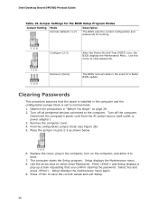
... BIOS displays the Maintenance Menu. Intel Desktop Board DP67BG Product Guide Table 15. Disconnect the computer's power cord from the AC power source (wall outlet or power adapter). 3. Use the arrow keys to save the current values and exit Setup. 56 Press to select Clear Passwords. Use this menu to boot. 7. Setup displays the Maintenance menu. 8. Replace the cover, plug in the computer and the configuration jumper block is set to the computer. Setup displays the maintenance menu again. 9. Turn off...
... BIOS displays the Maintenance Menu. Intel Desktop Board DP67BG Product Guide Table 15. Disconnect the computer's power cord from the AC power source (wall outlet or power adapter). 3. Use the arrow keys to save the current values and exit Setup. 56 Press to select Clear Passwords. Use this menu to boot. 7. Setup displays the Maintenance menu. 8. Replace the cover, plug in the computer and the configuration jumper block is set to the computer. Setup displays the maintenance menu again. 9. Turn off...
Product Guide
Page 70
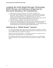
... beginning of Windows Setup, press to http://support.microsoft.com/kb/916196/en-us for Microsoft Windows XP Installation) 1. Install the Intel Rapid Storage Console software via the Intel Express Installer CD included with your Desktop Board or after downloading it from the Internet at http://support.intel.com/support/motherboards/desktop/. Finish the Windows installation and install all necessary drivers. 4. Intel Desktop Board DP67BG Product Guide Loading the Intel Rapid Storage Technology RAID Drivers and Software (Required for information on supported USB floppy disk drives.
... beginning of Windows Setup, press to http://support.microsoft.com/kb/916196/en-us for Microsoft Windows XP Installation) 1. Install the Intel Rapid Storage Console software via the Intel Express Installer CD included with your Desktop Board or after downloading it from the Internet at http://support.intel.com/support/motherboards/desktop/. Finish the Windows installation and install all necessary drivers. 4. Intel Desktop Board DP67BG Product Guide Loading the Intel Rapid Storage Technology RAID Drivers and Software (Required for information on supported USB floppy disk drives.
Product Guide
Page 71
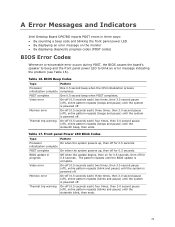
... and Indicators Intel Desktop Board DP67BG reports POST errors in progress Off when the update begins, then on the monitor • By displaying diagnostic progress codes (POST codes) BIOS Error Codes Whenever a recoverable error occurs during POST, the BIOS causes the board's speaker to beep and the front panel power LED to blink an error message indicating the problem (see Table 16). BIOS update in three ways: • By sounding a beep code and blinking the front panel power LED • By displaying an error message on...
... and Indicators Intel Desktop Board DP67BG reports POST errors in progress Off when the update begins, then on the monitor • By displaying diagnostic progress codes (POST codes) BIOS Error Codes Whenever a recoverable error occurs during POST, the BIOS causes the board's speaker to beep and the front panel power LED to blink an error message indicating the problem (see Table 16). BIOS update in three ways: • By sounding a beep code and blinking the front panel power LED • By displaying an error message on...
Product Specification
Page 6
...3.5 Legacy USB Support 63 3.6 BIOS Updates 64 3.6.1 Language Support 64 3.6.2 Custom Splash Screen 65 3.7 BIOS Recovery 65 3.8 Boot Options 66 3.8.1 Optical Drive Boot 66 3.8.2 Network Boot 66 3.8.3 Booting Without Attached Devices 66 3.8.4 Changing the Default Boot Device During POST 66 3.9 Adjusting Boot Speed 67 3.9.1 Peripheral Selection and Configuration 67 3.9.2 BIOS Boot Optimizations 67 3.10 BIOS Security Features 68 3.11 BIOS Performance Features 69 4 Error Messages and Beep Codes 4.1 Speaker 71 4.2 BIOS Beep Codes 71 4.3 Front-panel Power LED Blink Codes 72 4.4 BIOS...
...3.5 Legacy USB Support 63 3.6 BIOS Updates 64 3.6.1 Language Support 64 3.6.2 Custom Splash Screen 65 3.7 BIOS Recovery 65 3.8 Boot Options 66 3.8.1 Optical Drive Boot 66 3.8.2 Network Boot 66 3.8.3 Booting Without Attached Devices 66 3.8.4 Changing the Default Boot Device During POST 66 3.9 Adjusting Boot Speed 67 3.9.1 Peripheral Selection and Configuration 67 3.9.2 BIOS Boot Optimizations 67 3.10 BIOS Security Features 68 3.11 BIOS Performance Features 69 4 Error Messages and Beep Codes 4.1 Speaker 71 4.2 BIOS Beep Codes 71 4.3 Front-panel Power LED Blink Codes 72 4.4 BIOS...
Product Specification
Page 8
.... BIOS Beep Codes 71 34. Front Panel Header 49 21. Boot Device Menu Options 66 32. Front-panel Power LED Blink Codes 72 35. Port 80h POST Codes 74 39. Main Power Connector 48 20. EMC Regulations 83 32H 41. Fan Header Current Capability 56 26. Safety Standards 79 40. Thermal Considerations for a Two-Color Power LED 50 23. Supervisor and User Password Functions 68 33. Intel Desktop Board DP67BG Technical Product Specification 17. Recommended Power Supply Current Values 55 25. BIOS Error Messages...
.... BIOS Beep Codes 71 34. Front Panel Header 49 21. Boot Device Menu Options 66 32. Front-panel Power LED Blink Codes 72 35. Port 80h POST Codes 74 39. Main Power Connector 48 20. EMC Regulations 83 32H 41. Fan Header Current Capability 56 26. Safety Standards 79 40. Thermal Considerations for a Two-Color Power LED 50 23. Supervisor and User Password Functions 68 33. Intel Desktop Board DP67BG Technical Product Specification 17. Recommended Power Supply Current Values 55 25. BIOS Error Messages...
Product Specification
Page 20
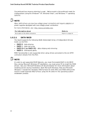
... PCH: • RAID 0 - data mirroring • RAID 0+1 (or RAID 10) - Also, during installation. Native mode is the preferred mode for both AHCI and RAID without the need to install separate RAID drivers using the F6 switch in the BIOS. distributed parity RAID functionality is used. data striping • RAID 1 - data striping and mirroring • RAID 5 - Intel Desktop Board DP67BG Technical Product Specification Conventional bus resource steering is only supported when using drives connected to the six SATA connectors (black) from...
... PCH: • RAID 0 - data mirroring • RAID 0+1 (or RAID 10) - Also, during installation. Native mode is the preferred mode for both AHCI and RAID without the need to install separate RAID drivers using the F6 switch in the BIOS. distributed parity RAID functionality is used. data striping • RAID 1 - data striping and mirroring • RAID 5 - Intel Desktop Board DP67BG Technical Product Specification Conventional bus resource steering is only supported when using drives connected to the six SATA connectors (black) from...
Product Specification
Page 24
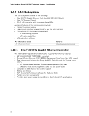
Intel Desktop Board DP67BG Technical Product Specification 1.10 LAN Subsystem The LAN subsystem consists of the following: • Intel 82579V Gigabit Ethernet Controller (10/100/1000 Mbits/s) • Intel P67 Express Chipset • RJ-45 LAN connector with integrated status LEDs Additional features of the LAN subsystem include: • CSMA/CD protocol engine • LAN connect interface between the PCH and the LAN controller • Conventional PCI bus power management ⎯ ACPI technology support ⎯ LAN wake capabilities •...
Intel Desktop Board DP67BG Technical Product Specification 1.10 LAN Subsystem The LAN subsystem consists of the following: • Intel 82579V Gigabit Ethernet Controller (10/100/1000 Mbits/s) • Intel P67 Express Chipset • RJ-45 LAN connector with integrated status LEDs Additional features of the LAN subsystem include: • CSMA/CD protocol engine • LAN connect interface between the PCH and the LAN controller • Conventional PCI bus power management ⎯ ACPI technology support ⎯ LAN wake capabilities •...
Product Specification
Page 61
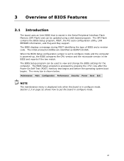
... BIOS Setup program, POST, the PCI auto-configuration utility, LAN EEPROM information, and Plug and Play support. The BIOS displays a message during POST identifying the type of BIOS Features 3.1 Introduction The board uses an Intel BIOS that is powered-up, the BIOS compares the CPU version and the microcode version in configure mode. The BIOS Setup program is shown below. The menu bar is accessed by pressing the key after the Power-On Self-Test (POST) memory test begins and before the operating system boot...
... BIOS Setup program, POST, the PCI auto-configuration utility, LAN EEPROM information, and Plug and Play support. The BIOS displays a message during POST identifying the type of BIOS Features 3.1 Introduction The board uses an Intel BIOS that is powered-up, the BIOS compares the CPU version and the microcode version in configure mode. The BIOS Setup program is shown below. The menu bar is accessed by pressing the key after the Power-On Self-Test (POST) memory test begins and before the operating system boot...
Product Specification
Page 62
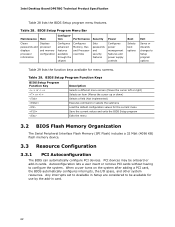
... Security Power Clears passwords and displays processor information Displays processor and memory configuration Configures advanced features available through the chipset Configures Memory, Bus and Processor overrides Sets passwords and security features Configures power management features and power supply controls Boot Selects boot options Exit Saves or discards changes to Setup program options Table 29 lists the function keys available for use by the add-in card. 62 PCI devices may be available for menu screens. BIOS Setup Program Menu Bar Maintenance Main Configura...
... Security Power Clears passwords and displays processor information Displays processor and memory configuration Configures advanced features available through the chipset Configures Memory, Bus and Processor overrides Sets passwords and security features Configures power management features and power supply controls Boot Selects boot options Exit Saves or discards changes to Setup program options Table 29 lists the function keys available for use by the add-in card. 62 PCI devices may be available for menu screens. BIOS Setup Program Menu Bar Maintenance Main Configura...
Product Specification
Page 66
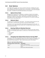
Boot devices are not present: • Video adapter • Keyboard • Mouse 3.8.4 Changing the Default Boot Device During POST Pressing the key during POST automatically forces booting from the LAN. Intel Desktop Board DP67BG Technical Product Specification 3.8 Boot Options In the BIOS Setup program, the user can be displayed. The default setting is supported in compliance to boot from a diskette drive, hard drive, USB drive, USB flash drive, optical drive, or the network. If enabled, the last default boot device is the network. 3.8.1 Optical Drive Boot Booting ...
Boot devices are not present: • Video adapter • Keyboard • Mouse 3.8.4 Changing the Default Boot Device During POST Pressing the key during POST automatically forces booting from the LAN. Intel Desktop Board DP67BG Technical Product Specification 3.8 Boot Options In the BIOS Setup program, the user can be displayed. The default setting is supported in compliance to boot from a diskette drive, hard drive, USB drive, USB flash drive, optical drive, or the network. If enabled, the last default boot device is the network. 3.8.1 Optical Drive Boot Booting ...
Product Specification
Page 73
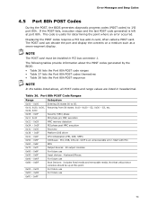
... devices: Keyboard/Mouse. 0xA0 - 0xAF For future use 0xF0 - 0xFF 73 This code is an unrecoverable error. Displaying the POST codes requires a PCI bus add-in hexadecimal. The POST card can decode the port and display the contents on a medium such as a seven-segment display. Start with PCI. S2, 0x30 - Not that critical since consoles should be installed in PCI bus connector 1. Error Messages and Beep Codes 4.5 Port 80h POST Codes During the POST, the BIOS generates diagnostic progress codes (POST codes...
... devices: Keyboard/Mouse. 0xA0 - 0xAF For future use 0xF0 - 0xFF 73 This code is an unrecoverable error. Displaying the POST codes requires a PCI bus add-in hexadecimal. The POST card can decode the port and display the contents on a medium such as a seven-segment display. Start with PCI. S2, 0x30 - Not that critical since consoles should be installed in PCI bus connector 1. Error Messages and Beep Codes 4.5 Port 80h POST Codes During the POST, the BIOS generates diagnostic progress codes (POST codes...


