
Product Guide
Page 5
...Supported Operating Systems 11 Desktop Board Components 12 Processor ...14 Main Memory...15 Intel® P67 Express Chipset 16 Audio Subsystem 16 LAN Subsystem 17 USB Support ...18 Serial ATA Support 18 Legacy I/O ...18 Expandability...18 BIOS ...19 Serial ATA Auto Configuration 19 PCI* and PCI Express* Auto ... from USB 23 PME# Signal Wake-up Support 23 WAKE# Signal Wake-up Support 23 Wake from Consumer IR 23 Onboard Power and Reset Buttons 24 Processor and Voltage Regulator LEDs 25 Diagnostic LEDs 26 Speaker...27 Battery ...27 Real-Time Clock 27 2 Installing and Replacing Desktop...
...Supported Operating Systems 11 Desktop Board Components 12 Processor ...14 Main Memory...15 Intel® P67 Express Chipset 16 Audio Subsystem 16 LAN Subsystem 17 USB Support ...18 Serial ATA Support 18 Legacy I/O ...18 Expandability...18 BIOS ...19 Serial ATA Auto Configuration 19 PCI* and PCI Express* Auto ... from USB 23 PME# Signal Wake-up Support 23 WAKE# Signal Wake-up Support 23 Wake from Consumer IR 23 Onboard Power and Reset Buttons 24 Processor and Voltage Regulator LEDs 25 Diagnostic LEDs 26 Speaker...27 Battery ...27 Real-Time Clock 27 2 Installing and Replacing Desktop...
Product Guide
Page 7
... ENERGY STAR*, e-Standby, and ErP Compliance 88 Figures 1. Onboard Power and Reset Buttons 24 5. Install the Processor 35 13. Secure the Load Plate in... Four DIMMs 39 17. Installing a DIMM 41 20. Intel Desktop Board DP67BG Components 12 2. Unlatch the Socket Lever 33 10. Intel Desktop Board DP67BG Mounting Screw Hole Locations 32 9. Installing the I/O Shield ...Certifications 86 Board-Level Certifications 86 Chassis- Contents A Error Messages and Indicators BIOS Error Codes 71 BIOS Error Messages 72 Port 80h POST Codes 73 B Regulatory Compliance Safety Standards ...
... ENERGY STAR*, e-Standby, and ErP Compliance 88 Figures 1. Onboard Power and Reset Buttons 24 5. Install the Processor 35 13. Secure the Load Plate in... Four DIMMs 39 17. Installing a DIMM 41 20. Intel Desktop Board DP67BG Components 12 2. Unlatch the Socket Lever 33 10. Intel Desktop Board DP67BG Mounting Screw Hole Locations 32 9. Installing the I/O Shield ...Certifications 86 Board-Level Certifications 86 Chassis- Contents A Error Messages and Indicators BIOS Error Codes 71 BIOS Error Messages 72 Port 80h POST Codes 73 B Regulatory Compliance Safety Standards ...
Product Guide
Page 13
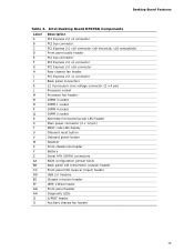
...connector (2 x 12 pin) POST code LED display Onboard reset button Onboard power button Speaker Front chassis fan header Battery Serial ATA (SATA) connectors BIOS configuration jumper block Back panel CIR transmitter (output) header ...Front panel CIR receiver (input) header USB 2.0 headers Chassis intrusion header IEEE 1394a header Front panel header Diagnostic LEDs S/PDIF header Auxiliary chassis fan header 13 Intel Desktop Board DP67BG Components Label A B C D E F G H ...
...connector (2 x 12 pin) POST code LED display Onboard reset button Onboard power button Speaker Front chassis fan header Battery Serial ATA (SATA) connectors BIOS configuration jumper block Back panel CIR transmitter (output) header ...Front panel CIR receiver (input) header USB 2.0 headers Chassis intrusion header IEEE 1394a header Front panel header Diagnostic LEDs S/PDIF header Auxiliary chassis fan header 13 Intel Desktop Board DP67BG Components Label A B C D E F G H ...
Product Guide
Page 19
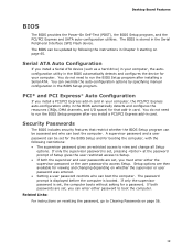
... need to access Setup. You do not need to run the BIOS Setup program after you must enter either password to Setup. • If both passwords are then available for viewing and changing depending on resetting the password, go to view and change all Setup options. Security... Passwords The BIOS includes security features that add-in the Serial Peripheral Interface (SPI) Flash device. The password prompt...
... need to access Setup. You do not need to run the BIOS Setup program after you must enter either password to Setup. • If both passwords are then available for viewing and changing depending on resetting the password, go to view and change all Setup options. Security... Passwords The BIOS includes security features that add-in the Serial Peripheral Interface (SPI) Flash device. The password prompt...

Product Guide
Page 26
Intel Desktop Board DP67BG Product Guide Diagnostic LEDs The Desktop Board provides eight LEDs that allow you to monitor the board's progress through the BIOS Power-on when processor initialization is complete. When the BIOS starts an activity such as memory initialization, the corresponding LED starts ...Green F Hard Drive Initialization Green G Option ROM Initialization Green H OS Start Green Description When the watch dog timer fires to reset the board, this LED will flash when the video initialization activity starts. Then the LED will stay on when hard drive initialization...
Intel Desktop Board DP67BG Product Guide Diagnostic LEDs The Desktop Board provides eight LEDs that allow you to monitor the board's progress through the BIOS Power-on when processor initialization is complete. When the BIOS starts an activity such as memory initialization, the corresponding LED starts ...Green F Hard Drive Initialization Green G Option ROM Initialization Green H OS Start Green Description When the watch dog timer fires to reset the board, this LED will flash when the video initialization activity starts. Then the LED will stay on when hard drive initialization...
Product Guide
Page 74
Intel Desktop Board DP67BG Product Guide POST Code 11 12 13 14 15 16 17, 18 19, 1A 1B, 1C 21 23 24 27 28 29 2A, 2B 31, ... CPU SMM init/relocate bases CPU DXE phase begin to end CPU DXE SMM phase begin to end I/O Buses PCI enumeration, allocation, hot plug Resetting USB bus Resetting SATA bus and all devices Unrecoverable error, start with PIC Boot Device Selection (BDS) BDS driver entry Entered DXE phase Waiting for user input...
Intel Desktop Board DP67BG Product Guide POST Code 11 12 13 14 15 16 17, 18 19, 1A 1B, 1C 21 23 24 27 28 29 2A, 2B 31, ... CPU SMM init/relocate bases CPU DXE phase begin to end CPU DXE SMM phase begin to end I/O Buses PCI enumeration, allocation, hot plug Resetting USB bus Resetting SATA bus and all devices Unrecoverable error, start with PIC Boot Device Selection (BDS) BDS driver entry Entered DXE phase Waiting for user input...
Product Specification
Page 12
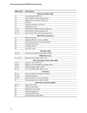
... power connector (2 x 12 pin) T POST code LED display U Onboard power button V Onboard reset button W Speaker X Front chassis fan header Y Battery Z Intel P67 Express Chipset AA SATA connectors (6) BB Consumer IR transmitter (output) header CC Consumer IR receiver... (input) header DD BIOS Setup configuration jumper block EE ...x16 connector (x8 electrical; Intel Desktop Board DP67BG Technical Product Specification Table 2.
... power connector (2 x 12 pin) T POST code LED display U Onboard power button V Onboard reset button W Speaker X Front chassis fan header Y Battery Z Intel P67 Express Chipset AA SATA connectors (6) BB Consumer IR transmitter (output) header CC Consumer IR receiver... (input) header DD BIOS Setup configuration jumper block EE ...x16 connector (x8 electrical; Intel Desktop Board DP67BG Technical Product Specification Table 2.

Product Specification
Page 21
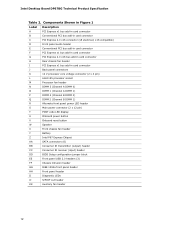
...hardware. NOTE If the battery and AC power fail date and time values will be reset and the user will be accurate. When the voltage drops below a certain level, the BIOS Setup program settings stored in order to emulate "learned" infrared commands in CMOS RAM...of a filtered translated infrared input compliant with Microsoft CIR specifications, and also a "learning" infrared input. This learning input is not plugged into Intel Desktop Boards for the I /O controller provides the following features: • Consumer Infrared (CIR) headers • Serial IRQ interface compatible with an...
...hardware. NOTE If the battery and AC power fail date and time values will be reset and the user will be accurate. When the voltage drops below a certain level, the BIOS Setup program settings stored in order to emulate "learned" infrared commands in CMOS RAM...of a filtered translated infrared input compliant with Microsoft CIR specifications, and also a "learning" infrared input. This learning input is not plugged into Intel Desktop Boards for the I /O controller provides the following features: • Consumer Infrared (CIR) headers • Serial IRQ interface compatible with an...

Product Specification
Page 36
... drive initialization is complete. Then the LED will stay on when USB initialization is complete. Just before BIOS transfers control to reset the board, this LED will light and stay on when the Back to BIOS button has been pressed. Diagnostic LEDs Item/Callout in Figure 7 Activity A Watch Dog Timer Fire/ Back to..., this LED will stay on when video initialization is complete. Then the LED will light and stay on . 36 In addition, this LED will flash. Intel Desktop Board DP67BG Technical Product Specification Table 9.
... drive initialization is complete. Then the LED will stay on when USB initialization is complete. Just before BIOS transfers control to reset the board, this LED will light and stay on when the Back to BIOS button has been pressed. Diagnostic LEDs Item/Callout in Figure 7 Activity A Watch Dog Timer Fire/ Back to..., this LED will stay on when video initialization is complete. Then the LED will light and stay on . 36 In addition, this LED will flash. Intel Desktop Board DP67BG Technical Product Specification Table 9.
Product Specification
Page 72
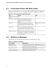
... since the last boot. No Boot Device Available System did not find a device to reset values. Front-panel Power LED Blink Codes Type Pattern F2 Setup/F10 Boot Menu None Prompt BIOS update in a total of each. This will be losing power. CMOS memory may be....25 seconds off, .25 seconds on for 0.5 seconds. Run Setup to boot. 72 Intel Desktop Board DP67BG Technical Product Specification 4.3 Front-panel Power LED Blink Codes Whenever a recoverable error occurs during POST, the BIOS causes the board's front panel power LED to blink an error message describing the problem (...
... since the last boot. No Boot Device Available System did not find a device to reset values. Front-panel Power LED Blink Codes Type Pattern F2 Setup/F10 Boot Menu None Prompt BIOS update in a total of each. This will be losing power. CMOS memory may be....25 seconds off, .25 seconds on for 0.5 seconds. Run Setup to boot. 72 Intel Desktop Board DP67BG Technical Product Specification 4.3 Front-panel Power LED Blink Codes Whenever a recoverable error occurs during POST, the BIOS causes the board's front panel power LED to blink an error message describing the problem (...
Product Specification
Page 77
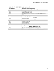
Port 80h POST Codes (continued) Port 80 Code Progress Code Enumeration Removable Media 0xB8 Resetting removable media 0xB9 Disabling removable media 0xBA Detecting presence of a removable media (IDE, CDROM detection etc.) 0xBB Enabling/configuring a ...removable media DXE Core 0xE4 Entered DXE phase BDS 0xE7 Waiting for user input 0xE8 Checking password 0xE9 Entering BIOS setup 0xEB Calling Legacy Option ROMs Runtime Phase/EFI OS Boot 0xF8 EFI boot service ExitBootServices ( ) has been called 0xF9 EFI runtime service ...
Port 80h POST Codes (continued) Port 80 Code Progress Code Enumeration Removable Media 0xB8 Resetting removable media 0xB9 Disabling removable media 0xBA Detecting presence of a removable media (IDE, CDROM detection etc.) 0xBB Enabling/configuring a ...removable media DXE Core 0xE4 Entered DXE phase BDS 0xE7 Waiting for user input 0xE8 Checking password 0xE9 Entering BIOS setup 0xEB Calling Legacy Option ROMs Runtime Phase/EFI OS Boot 0xF8 EFI boot service ExitBootServices ( ) has been called 0xF9 EFI runtime service ...
Product Specification
Page 78
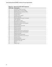
...Allocating resourced to PCI bus 92 Detecting the presence of the keyboard 90 Resetting keyboard 94 Clearing keyboard input buffer 95 Keyboard Self Test EB Calling Video BIOS 58 Resetting USB bus 5A Resetting PATA/SATA bus and all devices 92 Detecting the presence of the ...keyboard 90 Resetting keyboard 94 Clearing keyboard input buffer 5A Resetting PATA/SATA bus and all devices 28 Testing memory 90 Resetting keyboard 94 Clearing keyboard input buffer E7 Waiting for user input 01 INT 19 00 Ready to boot 78 Intel Desktop Board DP67BG Technical Product ...
...Allocating resourced to PCI bus 92 Detecting the presence of the keyboard 90 Resetting keyboard 94 Clearing keyboard input buffer 95 Keyboard Self Test EB Calling Video BIOS 58 Resetting USB bus 5A Resetting PATA/SATA bus and all devices 92 Detecting the presence of the ...keyboard 90 Resetting keyboard 94 Clearing keyboard input buffer 5A Resetting PATA/SATA bus and all devices 28 Testing memory 90 Resetting keyboard 94 Clearing keyboard input buffer E7 Waiting for user input 01 INT 19 00 Ready to boot 78 Intel Desktop Board DP67BG Technical Product ...


