
Product Specification
Page 5
... 1 Product Description 1.1 Overview 9 1.1.1 Feature Summary 9 1.1.2 Board Layout 11 1.1.3 Block Diagram 13 1.2 Legacy Considerations 14 1.3 Online Support 14 1.4 Processor 14 1.5 System Memory 15 1.5.1 Memory Configurations 17 1.6 Intel® P67 Express Chipset 19 1.6.1 PCI Express x16 Graphics 19 1.6.2 USB 19 1.6.3 SATA... 21 1.9 Audio Subsystem 22 1.9.1 Audio Subsystem Software 22 1.9.2 Audio Subsystem Components 22 1.10 LAN Subsystem 24 1.10.1 Intel® 82579V Gigabit Ethernet Controller 24 1.10.2 LAN Subsystem Software 25 1.10.3 RJ-45 LAN Connector with Integrated LEDs ...
... 1 Product Description 1.1 Overview 9 1.1.1 Feature Summary 9 1.1.2 Board Layout 11 1.1.3 Block Diagram 13 1.2 Legacy Considerations 14 1.3 Online Support 14 1.4 Processor 14 1.5 System Memory 15 1.5.1 Memory Configurations 17 1.6 Intel® P67 Express Chipset 19 1.6.1 PCI Express x16 Graphics 19 1.6.2 USB 19 1.6.3 SATA... 21 1.9 Audio Subsystem 22 1.9.1 Audio Subsystem Software 22 1.9.2 Audio Subsystem Components 22 1.10 LAN Subsystem 24 1.10.1 Intel® 82579V Gigabit Ethernet Controller 24 1.10.2 LAN Subsystem Software 25 1.10.3 RJ-45 LAN Connector with Integrated LEDs ...
Product Specification
Page 7
...108H 28H 5. Diagnostic LEDs 36 13H 293H 10. Front Panel Audio Header 45 17H 297H 14. Block Diagram 13 90H 270H 3. LAN Connector LED Locations 25 93H 273H 6. Connection Diagram for Front Panel Header 49 10H 280H 13. Board Dimensions 54 103H 283H 16. Components Shown in ... Devices and Events 31 12H 29H 9. Chassis Intrusion Header 46 120H 30H vii Detailed System Memory Address Map 40 97H 27H 10. Connection Diagram for Front Panel USB Headers 51 10H 281H 14. System Memory Map 41 14H 294H 11. IEEE 1394a Header 45 16H 296H 13. ...
...108H 28H 5. Diagnostic LEDs 36 13H 293H 10. Front Panel Audio Header 45 17H 297H 14. Block Diagram 13 90H 270H 3. LAN Connector LED Locations 25 93H 273H 6. Connection Diagram for Front Panel Header 49 10H 280H 13. Board Dimensions 54 103H 283H 16. Components Shown in ... Devices and Events 31 12H 29H 9. Chassis Intrusion Header 46 120H 30H vii Detailed System Memory Address Map 40 97H 27H 10. Connection Diagram for Front Panel USB Headers 51 10H 281H 14. System Memory Map 41 14H 294H 11. IEEE 1394a Header 45 16H 296H 13. ...
Product Specification
Page 13
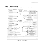
Product Description 1.1.3 Block Diagram Figure 2 is a block diagram of the major functional areas of the board. Block Diagram 13 Figure 2.
Product Description 1.1.3 Block Diagram Figure 2 is a block diagram of the major functional areas of the board. Block Diagram 13 Figure 2.
Product Specification
Page 49
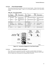
... Front Panel Header 2.2.2.4.1 Hard Drive Activity LED Header Pins 1 and 3 can be connected to an LED to provide a visual indicator that data is a connection diagram for the front panel header. Proper LED function requires a SATA hard drive or optical drive connected to a hard drive. Front Panel Header Pin Signal In/ ...
... Front Panel Header 2.2.2.4.1 Hard Drive Activity LED Header Pins 1 and 3 can be connected to an LED to provide a visual indicator that data is a connection diagram for the front panel header. Proper LED function requires a SATA hard drive or optical drive connected to a hard drive. Front Panel Header Pin Signal In/ ...
Product Specification
Page 51
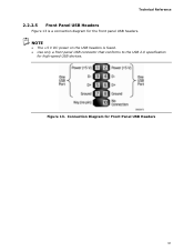
Figure 13. NOTE • The +5 V DC power on the USB headers is a connection diagram for the front panel USB headers. Connection Diagram for high-speed USB devices. Technical Reference 2.2.2.5 Front Panel USB Headers Figure 13 is fused. • Use only a front panel USB connector that conforms to the USB 2.0 specification for Front Panel USB Headers 51
Figure 13. NOTE • The +5 V DC power on the USB headers is a connection diagram for the front panel USB headers. Connection Diagram for high-speed USB devices. Technical Reference 2.2.2.5 Front Panel USB Headers Figure 13 is fused. • Use only a front panel USB connector that conforms to the USB 2.0 specification for Front Panel USB Headers 51


