

Product Guide
Page 6
Intel Desktop Board DP67BG Product Guide Installing a Processor 33 Installing the Processor Fan Heat Sink 37 Connecting the Processor Fan Heat Sink Cable 37 Removing the Processor 37 Installing and Removing System Memory 38 Guidelines for Dual Channel Memory Configuration 38 Two ...BIOS Configuration Jumper 55 Clearing Passwords 56 Replacing the Battery 57 Installing the WiFi/Bluetooth* Module in a Desktop Chassis 63 3 Updating the BIOS Updating the BIOS with the Intel® Express BIOS Update Utility 65 Updating the BIOS Using the F7 Function Key 66 Updating the BIOS with the Intel...
Intel Desktop Board DP67BG Product Guide Installing a Processor 33 Installing the Processor Fan Heat Sink 37 Connecting the Processor Fan Heat Sink Cable 37 Removing the Processor 37 Installing and Removing System Memory 38 Guidelines for Dual Channel Memory Configuration 38 Two ...BIOS Configuration Jumper 55 Clearing Passwords 56 Replacing the Battery 57 Installing the WiFi/Bluetooth* Module in a Desktop Chassis 63 3 Updating the BIOS Updating the BIOS with the Intel® Express BIOS Update Utility 65 Updating the BIOS Using the F7 Function Key 66 Updating the BIOS with the Intel...
Product Guide
Page 8
Location of the BIOS Configuration Jumper Block 55 29. Location of the Chassis Fan Headers 53 27. Diagnostic LEDs 26 6. Chassis Intrusion Header Signal Names 51 15. Back Panel Audio Connectors ... POST Codes 73 20. Intel Desktop Board DP67BG Components 13 3. Alternate Front Panel Power LED Header Signal Names 49 10. BIOS Error Messages 72 19. Intel Desktop Board DP67BG Product Guide 25. S/PDIF Header Signal Names 48 7. Regulatory Compliance Marks 86 viii Connecting Power Supply Cables 54 28. Jumper Settings for the BIOS Setup Program Modes 56...
Location of the BIOS Configuration Jumper Block 55 29. Location of the Chassis Fan Headers 53 27. Diagnostic LEDs 26 6. Chassis Intrusion Header Signal Names 51 15. Back Panel Audio Connectors ... POST Codes 73 20. Intel Desktop Board DP67BG Components 13 3. Alternate Front Panel Power LED Header Signal Names 49 10. BIOS Error Messages 72 19. Intel Desktop Board DP67BG Product Guide 25. S/PDIF Header Signal Names 48 7. Regulatory Compliance Marks 86 viii Connecting Power Supply Cables 54 28. Jumper Settings for the BIOS Setup Program Modes 56...
Product Guide
Page 13
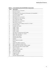
... chassis fan header Battery Serial ATA (SATA) connectors BIOS configuration jumper block Back panel CIR transmitter (output) header Front panel CIR receiver (input) header USB 2.0 headers Chassis intrusion header IEEE 1394a header Front panel header Diagnostic LEDs S/PDIF header Auxiliary chassis fan header 13 Intel Desktop Board DP67BG Components Label A B C D E F G H I J K L M N O P Q R S T U V W X Y Z AA BB CC DD EE...
... chassis fan header Battery Serial ATA (SATA) connectors BIOS configuration jumper block Back panel CIR transmitter (output) header Front panel CIR receiver (input) header USB 2.0 headers Chassis intrusion header IEEE 1394a header Front panel header Diagnostic LEDs S/PDIF header Auxiliary chassis fan header 13 Intel Desktop Board DP67BG Components Label A B C D E F G H I J K L M N O P Q R S T U V W X Y Z AA BB CC DD EE...
Product Guide
Page 20
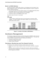
... management. Fan speed controllers and sensors are integrated into the legacy I /O controller, delivering acoustically- Intel Desktop Board DP67BG Product Guide Back to BIOS Button The back panel Back to BIOS button (Figure 3, A) duplicates the functionality of the BIOS configuration jumper (see Setting the BIOS Configuration Jumper on page 55) with the Wired for Management (WfM) specification. To restore settings to...
... management. Fan speed controllers and sensors are integrated into the legacy I /O controller, delivering acoustically- Intel Desktop Board DP67BG Product Guide Back to BIOS Button The back panel Back to BIOS button (Figure 3, A) duplicates the functionality of the BIOS configuration jumper (see Setting the BIOS Configuration Jumper on page 55) with the Wired for Management (WfM) specification. To restore settings to...

Product Guide
Page 29
... cables • Connect to the internal headers • Connect to the audio system • Connect chassis fan and power supply cables • Set the BIOS configuration jumper • Clear passwords • Replace the battery • Install the WiFi/BlueTooth Module Before You Begin CAUTIONS The procedures in this chapter assume familiarity with... each procedure in the correct order. • Set up a log to record information about your computer, such as model, serial numbers, installed options, and configuration information. • Electrostatic discharge (ESD) can damage components.
... cables • Connect to the internal headers • Connect to the audio system • Connect chassis fan and power supply cables • Set the BIOS configuration jumper • Clear passwords • Replace the battery • Install the WiFi/BlueTooth Module Before You Begin CAUTIONS The procedures in this chapter assume familiarity with... each procedure in the correct order. • Set up a log to record information about your computer, such as model, serial numbers, installed options, and configuration information. • Electrostatic discharge (ESD) can damage components.
Product Guide
Page 55
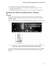
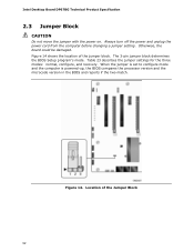
... 27, C). Connect the main power supply cable to the 2 x 4 pin connector (Figure 27, A). 3. Moving the jumper with the power on page 29. 2. Figure 28 shows the location of the BIOS Configuration Jumper Block The three-pin BIOS jumper block enables board configuration to be done in unreliable computer operation. Installing and Replacing Desktop Board Components 1. Figure 28...
... 27, C). Connect the main power supply cable to the 2 x 4 pin connector (Figure 27, A). 3. Moving the jumper with the power on page 29. 2. Figure 28 shows the location of the BIOS Configuration Jumper Block The three-pin BIOS jumper block enables board configuration to be done in unreliable computer operation. Installing and Replacing Desktop Board Components 1. Figure 28...
Product Guide
Page 56
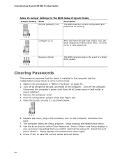
... computer and the configuration jumper block is installed in the computer, turn on pins 2-3 as shown below. 6. Turn off all peripheral devices connected to clear passwords. Setup displays the maintenance menu again. 9. Use this menu to the computer. Observe the precautions in the event of a failed BIOS update. Intel Desktop Board DP67BG Product Guide Table...
... computer and the configuration jumper block is installed in the computer, turn on pins 2-3 as shown below. 6. Turn off all peripheral devices connected to clear passwords. Setup displays the maintenance menu again. 9. Use this menu to the computer. Observe the precautions in the event of a failed BIOS update. Intel Desktop Board DP67BG Product Guide Table...

Product Guide
Page 67
... of an Intel® Desktop Board BIOS to remove the BIOS configuration jumper. Manually run the IFLASH.EXE file from a bootable CD-ROM, bootable USB flash drive, or other bootable USB media. Uncompress the BIOS update file and copy the .BIO file, IFLASH.EXE, and .ITK file (optional) to the Intel Desktop Board DP67BG page on the Intel World Wide...
... of an Intel® Desktop Board BIOS to remove the BIOS configuration jumper. Manually run the IFLASH.EXE file from a bootable CD-ROM, bootable USB flash drive, or other bootable USB media. Uncompress the BIOS update file and copy the .BIO file, IFLASH.EXE, and .ITK file (optional) to the Intel Desktop Board DP67BG page on the Intel World Wide...
Product Specification
Page 6
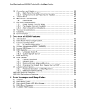
Intel Desktop Board DP67BG Technical Product Specification 2.2 Connectors and Headers 41 2.2.1 Back Panel Connectors 42 2.2.2 Component-side Connectors and Headers 43 2.3 Jumper Block 52... 2.4 Mechanical Considerations 54 2.4.1 Form Factor 54 2.5 Electrical Considerations 55 2.5.1 Power Supply Considerations 55 2.5.2 Fan Header Current Capability 56 2.5.3 Add-in Board Considerations 56 2.6 Thermal Considerations 57 2.7 Reliability 59 2.8 Environmental 59 3 Overview of BIOS Features 3.1 Introduction 61 3.2 BIOS Flash Memory Organization 62 3.3 Resource Configuration...
Intel Desktop Board DP67BG Technical Product Specification 2.2 Connectors and Headers 41 2.2.1 Back Panel Connectors 42 2.2.2 Component-side Connectors and Headers 43 2.3 Jumper Block 52... 2.4 Mechanical Considerations 54 2.4.1 Form Factor 54 2.5 Electrical Considerations 55 2.5.1 Power Supply Considerations 55 2.5.2 Fan Header Current Capability 56 2.5.3 Add-in Board Considerations 56 2.6 Thermal Considerations 57 2.7 Reliability 59 2.8 Environmental 59 3 Overview of BIOS Features 3.1 Introduction 61 3.2 BIOS Flash Memory Organization 62 3.3 Resource Configuration...
Product Specification
Page 8
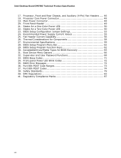
.... States for Components 58 27. BIOS Setup Configuration Jumper Settings 53 24. BIOS Setup Program Menu Bar 62 29. Boot Device Menu Options 66 32. Safety Standards 79 40. Thermal Considerations for a Two-Color Power LED 50 23. BIOS Beep Codes 71 34. Regulatory Compliance...20. BIOS Setup Program Function Keys 62 30. Processor, Front and Rear Chassis, and Auxiliary (4-Pin) Fan Headers ..... 46 18. Fan Header Current Capability 56 26. Supervisor and User Password Functions 68 33. EMC Regulations 83 32H 41. Intel Desktop Board DP67BG Technical ...
.... States for Components 58 27. BIOS Setup Configuration Jumper Settings 53 24. BIOS Setup Program Menu Bar 62 29. Boot Device Menu Options 66 32. Safety Standards 79 40. Thermal Considerations for a Two-Color Power LED 50 23. BIOS Beep Codes 71 34. Regulatory Compliance...20. BIOS Setup Program Function Keys 62 30. Processor, Front and Rear Chassis, and Auxiliary (4-Pin) Fan Headers ..... 46 18. Fan Header Current Capability 56 26. Supervisor and User Password Functions 68 33. EMC Regulations 83 32H 41. Intel Desktop Board DP67BG Technical ...
Product Specification
Page 12
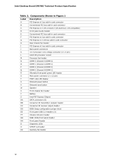
Intel Desktop Board DP67BG Technical Product Specification Table 2. Components Shown in Figure 1 Label Description A PCI Express x1 bus add-in card connector B Conventional PCI bus add-in card ...LED display U Onboard power button V Onboard reset button W Speaker X Front chassis fan header Y Battery Z Intel P67 Express Chipset AA SATA connectors (6) BB Consumer IR transmitter (output) header CC Consumer IR receiver (input) header DD BIOS Setup configuration jumper block EE Front panel USB 2.0 headers (3) FF Chassis intrusion header GG IEEE 1394a front panel...
Intel Desktop Board DP67BG Technical Product Specification Table 2. Components Shown in Figure 1 Label Description A PCI Express x1 bus add-in card connector B Conventional PCI bus add-in card ...LED display U Onboard power button V Onboard reset button W Speaker X Front chassis fan header Y Battery Z Intel P67 Express Chipset AA SATA connectors (6) BB Consumer IR transmitter (output) header CC Consumer IR receiver (input) header DD BIOS Setup configuration jumper block EE Front panel USB 2.0 headers (3) FF Chassis intrusion header GG IEEE 1394a front panel...
Product Specification
Page 52
... the jumper is set to configure mode and the computer is powered-up, the BIOS compares the processor version and the microcode version in the BIOS and reports if the two match. Always turn off the power and unplug the power cord from the computer before changing a jumper setting. Intel Desktop Board DP67BG Technical Product Specification 2.3 Jumper Block...
... the jumper is set to configure mode and the computer is powered-up, the BIOS compares the processor version and the microcode version in the BIOS and reports if the two match. Always turn off the power and unplug the power cord from the computer before changing a jumper setting. Intel Desktop Board DP67BG Technical Product Specification 2.3 Jumper Block...
Product Specification
Page 53
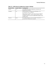
The maintenance menu is the only way to clear the BIOS/CMOS settings. Note that this Configure mode is displayed. BIOS Setup Configuration Jumper Settings Function/Mode Normal Configure Jumper Setting 1-2 2-3 Configuration The BIOS uses current configuration information and passwords for booting. After the POST runs, Setup runs automatically. Recovery None The BIOS attempts to their default values. Technical Reference Table 23...
The maintenance menu is the only way to clear the BIOS/CMOS settings. Note that this Configure mode is displayed. BIOS Setup Configuration Jumper Settings Function/Mode Normal Configure Jumper Setting 1-2 2-3 Configuration The BIOS uses current configuration information and passwords for booting. After the POST runs, Setup runs automatically. Recovery None The BIOS attempts to their default values. Technical Reference Table 23...
Product Specification
Page 61
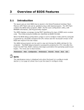
When the BIOS Setup configuration jumper is powered-up, the BIOS compares the CPU version and the microcode version in configure mode. 61 Maintenance Main Configuration Performance Security Power Boot Exit NOTE The maintenance menu is displayed only when the board is shown below. Section 2.3 on page 52 shows how to configure mode and the computer is set...
When the BIOS Setup configuration jumper is powered-up, the BIOS compares the CPU version and the microcode version in configure mode. 61 Maintenance Main Configuration Performance Security Power Boot Exit NOTE The maintenance menu is displayed only when the board is shown below. Section 2.3 on page 52 shows how to configure mode and the computer is set...

Product Specification
Page 64
... attempting a BIOS update. Intel Desktop Board DP67BG Technical Product Specification To install an operating system that supports USB, verify that Legacy USB support in the BIOS Setup program is located and perform the update from that the updated BIOS matches the target system to performing a BIOS Recovery without removing the BIOS configuration jumper. Using this utility, the BIOS can be...
... attempting a BIOS update. Intel Desktop Board DP67BG Technical Product Specification To install an operating system that supports USB, verify that Legacy USB support in the BIOS Setup program is located and perform the update from that the updated BIOS matches the target system to performing a BIOS Recovery without removing the BIOS configuration jumper. Using this utility, the BIOS can be...

