
Technical Product Specification
Page 5
... the BIOS error messages, beep codes, and POST codes Regulatory compliance and battery disposal information Typographical Conventions This section contains information about Intel NUC Board D53427RKE and its components to the vendors, system integrators, and other engineers and technicians who need this level of information. CAUTION Cautions are included to important information. Preface This Technical Product Specification (TPS) specifies the board layout, components, connectors, power...
... the BIOS error messages, beep codes, and POST codes Regulatory compliance and battery disposal information Typographical Conventions This section contains information about Intel NUC Board D53427RKE and its components to the vendors, system integrators, and other engineers and technicians who need this level of information. CAUTION Cautions are included to important information. Preface This Technical Product Specification (TPS) specifies the board layout, components, connectors, power...
Technical Product Specification
Page 8
... 60 3 Overview of BIOS Features 3.1 Introduction 61 3.2 BIOS Flash Memory Organization 62 3.3 System Management BIOS (SMBIOS 62 3.4 Legacy USB Support 62 3.5 BIOS Updates 63 3.5.1 Language Support 63 3.5.2 Custom Splash Screen 64 3.6 BIOS Recovery 64 3.7 Boot Options 65 3.7.1 Network Boot 65 3.7.2 Booting Without Attached Devices 65 3.7.3 Changing the Default Boot Device During POST 65 3.8 Hard Disk Drive Password Security Feature 66 3.9 BIOS Security Features 67 4 Error Messages and Blink Codes 4.1 Front-panel Power LED Blink Codes 69 4.2 BIOS Error Messages 69 5 Regulatory...
... 60 3 Overview of BIOS Features 3.1 Introduction 61 3.2 BIOS Flash Memory Organization 62 3.3 System Management BIOS (SMBIOS 62 3.4 Legacy USB Support 62 3.5 BIOS Updates 63 3.5.1 Language Support 63 3.5.2 Custom Splash Screen 64 3.6 BIOS Recovery 64 3.7 Boot Options 65 3.7.1 Network Boot 65 3.7.2 Booting Without Attached Devices 65 3.7.3 Changing the Default Boot Device During POST 65 3.8 Hard Disk Drive Password Security Feature 66 3.9 BIOS Security Features 67 4 Error Messages and Blink Codes 4.1 Front-panel Power LED Blink Codes 69 4.2 BIOS Error Messages 69 5 Regulatory...

Technical Product Specification
Page 9
... 43 9. Location of the Standby Power LED 35 8. PCI Express Full-/Half-Mini Card Connector 46 12. Dual-Port Front Panel USB 2.0 Header 48 13. 19 V Internal Power Supply Connector 49 14. BIOS Setup Configuration Jumper Settings 53 17. Fan Header Current Capability 57 19. Master Key and User Hard Drive Password Functions 66 25. Board Dimensions 55 15. Supported Memory Configurations 19 5. Triple Display Configuration Resolutions 24 6. Effects of Pressing the Power Switch 31 8. Boot Device Menu Options 65 24. Front-panel Power LED Blink Codes 69 ix...
... 43 9. Location of the Standby Power LED 35 8. PCI Express Full-/Half-Mini Card Connector 46 12. Dual-Port Front Panel USB 2.0 Header 48 13. 19 V Internal Power Supply Connector 49 14. BIOS Setup Configuration Jumper Settings 53 17. Fan Header Current Capability 57 19. Master Key and User Hard Drive Password Functions 66 25. Board Dimensions 55 15. Supported Memory Configurations 19 5. Triple Display Configuration Resolutions 24 6. Effects of Pressing the Power Switch 31 8. Boot Device Menu Options 65 24. Front-panel Power LED Blink Codes 69 ix...

Technical Product Specification
Page 11
...; One PCI Express Full-Mini Card connector • Intel® Visual BIOS resident in the Serial Peripheral Interface (SPI) Flash device • Support for 1.35 V low voltage JEDEC memory Intel® QS77 Express Chipset consisting of the board. 1 Product Description 1.1 Overview 1.1.1 Feature Summary Table 1 summarizes the major features of the Intel® QS77 Express Platform Controller Hub (PCH) • Integrated graphics support for processors with Intel® Graphics Technology: ― One High Definition Multimedia Interface* (HDMI*) back panel connector...
...; One PCI Express Full-Mini Card connector • Intel® Visual BIOS resident in the Serial Peripheral Interface (SPI) Flash device • Support for 1.35 V low voltage JEDEC memory Intel® QS77 Express Chipset consisting of the board. 1 Product Description 1.1 Overview 1.1.1 Feature Summary Table 1 summarizes the major features of the Intel® QS77 Express Platform Controller Hub (PCH) • Integrated graphics support for processors with Intel® Graphics Technology: ― One High Definition Multimedia Interface* (HDMI*) back panel connector...
Technical Product Specification
Page 18
....htm http://www.intel.com/p/en_US/support?iid=hdr+support http://ark.intel.com Chipset information BIOS and driver updates Tested memory Integration information https://wwwssl.intel.com/content/www/us/en/chipsets/performancechipsets/chipsets.html http://downloadcenter.intel.com http://www.intel.com/support/motherboards/desktop/sb/CS025414.htm http://www.intel.com/support/go/buildit 1.3 Processor The board has a soldered-down Intel Core i5-3427 processor with Integrated Graphics Technology and integrated memory controller. Refer to...
....htm http://www.intel.com/p/en_US/support?iid=hdr+support http://ark.intel.com Chipset information BIOS and driver updates Tested memory Integration information https://wwwssl.intel.com/content/www/us/en/chipsets/performancechipsets/chipsets.html http://downloadcenter.intel.com http://www.intel.com/support/motherboards/desktop/sb/CS025414.htm http://www.intel.com/support/go/buildit 1.3 Processor The board has a soldered-down Intel Core i5-3427 processor with Integrated Graphics Technology and integrated memory controller. Refer to...
Technical Product Specification
Page 19
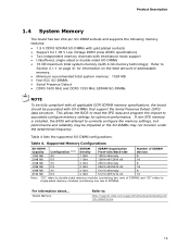
... installed, the BIOS will attempt to : http://support.intel.com/support/motherboards/desktop/sb /CS-025414.htm 19 This allows the BIOS to read the SPD data and program the chipset to Section 2.1.1 on the total amount of SDRAM). Table 4 lists the supported SO-DIMM configurations. Table 4. For information about... Product Description 1.4 System Memory The board has two 204-pin SO-DIMM sockets and supports the following memory...
... installed, the BIOS will attempt to : http://support.intel.com/support/motherboards/desktop/sb /CS-025414.htm 19 This allows the BIOS to read the SPD data and program the chipset to Section 2.1.1 on the total amount of SDRAM). Table 4 lists the supported SO-DIMM configurations. Table 4. For information about... Product Description 1.4 System Memory The board has two 204-pin SO-DIMM sockets and supports the following memory...
Technical Product Specification
Page 22
... wired displays (HDMI). 22 Intel NUC D53427RKE Technical Product Specification 1.5 Intel® QS77 Express Chipset Intel QS77 Express Chipset with the display interfaces on the PCH. The Intel QS77 Express Chipset is transcoded as per the display protocol and driven to the display monitor. 1.5.2.2 High-bandwidth Digital Content Protection (HDCP) HDCP is the technology for concurrent traffic and true isochronous transfer capabilities. 1.5.2 Display Interfaces Display is the chip-to the processor and the USB, SATA, LPC, LAN, and PCI Express...
... wired displays (HDMI). 22 Intel NUC D53427RKE Technical Product Specification 1.5 Intel® QS77 Express Chipset Intel QS77 Express Chipset with the display interfaces on the PCH. The Intel QS77 Express Chipset is transcoded as per the display protocol and driven to the display monitor. 1.5.2.2 High-bandwidth Digital Content Protection (HDCP) HDCP is the technology for concurrent traffic and true isochronous transfer capabilities. 1.5.2 Display Interfaces Display is the chip-to the processor and the USB, SATA, LPC, LAN, and PCI Express...
Technical Product Specification
Page 23
Product Description 1.6 Graphics Subsystem The board supports graphics through Intel Graphics Technology. 1.6.1 Integrated Graphics The board supports integrated graphics through Intel FDI. 1.6.1.1 Intel® High Definition (Intel® HD) Graphics The Intel HD graphics controller features the following: • 3D Features DirectX* 10.1 and OpenGL* 3.0 compliant DirectX 11.0 CS4.0 only Shader Model 4.0 • Video High-Definition content at 24-bit/96 kHz audio of lossless audio formats such as graphics memory to the configured maximum...
Product Description 1.6 Graphics Subsystem The board supports graphics through Intel Graphics Technology. 1.6.1 Integrated Graphics The board supports integrated graphics through Intel FDI. 1.6.1.1 Intel® High Definition (Intel® HD) Graphics The Intel HD graphics controller features the following: • 3D Features DirectX* 10.1 and OpenGL* 3.0 compliant DirectX 11.0 CS4.0 only Shader Model 4.0 • Video High-Definition content at 24-bit/96 kHz audio of lossless audio formats such as graphics memory to the configured maximum...
Technical Product Specification
Page 25
... panel The location of the front panel USB headers Refer to use AHCI mode, AHCI must be enabled in the BIOS. The PCH supports HDCP 1.4 for the PCI Express Full-Mini Card • One front panel USB 3.0 port is implemented through one dual-port internal header Two ports are implemented with vertical back panel connectors One port is reserved for the PCI Express Half-Mini Card One port is reserved for content protection over wired displays (HDMI and DisplayPort). 1.6.2 USB The board supports USB 2.0/3.0 ports...
... panel The location of the front panel USB headers Refer to use AHCI mode, AHCI must be enabled in the BIOS. The PCH supports HDCP 1.4 for the PCI Express Full-Mini Card • One front panel USB 3.0 port is implemented through one dual-port internal header Two ports are implemented with vertical back panel connectors One port is reserved for the PCI Express Half-Mini Card One port is reserved for content protection over wired displays (HDMI and DisplayPort). 1.6.2 USB The board supports USB 2.0/3.0 ports...
Technical Product Specification
Page 26
... three years. Intel NUC D53427RKE Technical Product Specification 1.7 Real-Time Clock Subsystem A coin-cell battery (CR2032) powers the real-time clock and CMOS memory. When the computer is accurate to http://downloadcenter.intel.com 26 Replace the battery with integrated status LEDs Additional features of the following: • Intel 82579LM Gigabit Ethernet Controller (10/100/1000 Mb/s) • Intel QS77 Express Chipset • RJ-45 LAN connector with an equivalent...
... three years. Intel NUC D53427RKE Technical Product Specification 1.7 Real-Time Clock Subsystem A coin-cell battery (CR2032) powers the real-time clock and CMOS memory. When the computer is accurate to http://downloadcenter.intel.com 26 Replace the battery with integrated status LEDs Additional features of the following: • Intel 82579LM Gigabit Ethernet Controller (10/100/1000 Mb/s) • Intel QS77 Express Chipset • RJ-45 LAN connector with an equivalent...
Technical Product Specification
Page 31
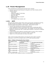
... seconds Power-on power management settings in boards may require an ACPI-aware driver), video displays, and hard disk drives • Methods for ...the system enters this ...and the power switch is state... The use of a computer. Product Description 1.10 Power Management Power management is implemented at several levels, including: • Software support through Advanced Configuration and Power Interface (ACPI) • Hardware support: Power Input Instantly Available PC technology LAN wake capabilities Wake from...
... seconds Power-on power management settings in boards may require an ACPI-aware driver), video displays, and hard disk drives • Methods for ...the system enters this ...and the power switch is state... The use of a computer. Product Description 1.10 Power Management Power management is implemented at several levels, including: • Software support through Advanced Configuration and Power Interface (ACPI) • Hardware support: Power Input Instantly Available PC technology LAN wake capabilities Wake from...
Technical Product Specification
Page 34
The LAN subsystem monitors network traffic at the Media Independent Interface. NOTE Wake from USB requires the use of Instantly Available PC technology requires operating system support and drivers for any installed PCI Express add-in the BIOS Setup program's Boot menu. Intel NUC D53427RKE Technical Product Specification 1.10.2.1 Power Input When resuming from an AC power failure, the computer returns to the power state it was interrupted (on or off). The computer's response...
The LAN subsystem monitors network traffic at the Media Independent Interface. NOTE Wake from USB requires the use of Instantly Available PC technology requires operating system support and drivers for any installed PCI Express add-in the BIOS Setup program's Boot menu. Intel NUC D53427RKE Technical Product Specification 1.10.2.1 Power Input When resuming from an AC power failure, the computer returns to the power state it was interrupted (on or off). The computer's response...
Technical Product Specification
Page 51
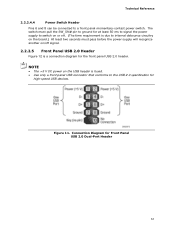
... a connection diagram for high-speed USB devices. Figure 11. NOTE • The +5 V DC power on /off . (The time requirement is due to internal debounce circuitry on the board.) At least two seconds must pull the SW_ON# pin to ground for at least 50 ms to signal the power supply to switch on or off signal. 2.2.2.5 Front Panel USB 2.0 Header Figure 12 is fused. • Use only a front panel USB connector...
... a connection diagram for high-speed USB devices. Figure 11. NOTE • The +5 V DC power on /off . (The time requirement is due to internal debounce circuitry on the board.) At least two seconds must pull the SW_ON# pin to ground for at least 50 ms to signal the power supply to switch on or off signal. 2.2.2.5 Front Panel USB 2.0 Header Figure 12 is fused. • Use only a front panel USB connector...

Technical Product Specification
Page 53
...Engine BIOS Extension (Intel® MEBX) Reset Header The Intel® MEBX reset header (see Figure 13) allows you to reset the Intel ME configuration to recover the BIOS configuration. NOTE After using the MEBX Reset, a "CMOS battery failure" warning will accomplish the following: • Return all Intel ME parameters to clear the BIOS/CMOS settings. A recovery CD or flash drive is displayed. BIOS Setup Configuration Jumper Settings Function/Mode Normal Configure Jumper Setting 1-2 2-3 Configuration The BIOS uses current configuration information and passwords for the jumper...
...Engine BIOS Extension (Intel® MEBX) Reset Header The Intel® MEBX reset header (see Figure 13) allows you to reset the Intel ME configuration to recover the BIOS configuration. NOTE After using the MEBX Reset, a "CMOS battery failure" warning will accomplish the following: • Return all Intel ME parameters to clear the BIOS/CMOS settings. A recovery CD or flash drive is displayed. BIOS Setup Configuration Jumper Settings Function/Mode Normal Configure Jumper Setting 1-2 2-3 Configuration The BIOS uses current configuration information and passwords for the jumper...
Technical Product Specification
Page 62
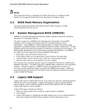
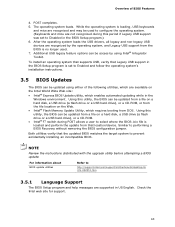
... as memory size, cache size, and processor speed • Dynamic data, such as follows: 1. POST begins. 3. The BIOS supports an SMBIOS table interface for such operating systems. Using this information. By default, Legacy USB support is set to use a USB keyboard to install an operating system that supports USB. The main component of SMBIOS is disabled. 2. Legacy USB support is enabled by the BIOS allowing you apply power to put the board in configure mode. 3.2 BIOS Flash Memory Organization The Serial Peripheral Interface Flash Memory (SPI Flash) includes...
... as memory size, cache size, and processor speed • Dynamic data, such as follows: 1. POST begins. 3. The BIOS supports an SMBIOS table interface for such operating systems. Using this information. By default, Legacy USB support is set to use a USB keyboard to install an operating system that supports USB. The main component of SMBIOS is disabled. 2. Legacy USB support is enabled by the BIOS allowing you apply power to put the board in configure mode. 3.2 BIOS Flash Memory Organization The Serial Peripheral Interface Flash Memory (SPI Flash) includes...
Technical Product Specification
Page 63
... to Disabled in the BIOS Setup program.) 6. Overview of the following utilities, which are available on a hard disk, a USB drive (a flash drive or a USB hard drive), or a CD-ROM. • Intel® F7 switch during this utility, the BIOS can be updated from a file on a hard disk, a USB drive (a flash drive or a USB hard drive), or a CD-ROM, or from the file location on the Web. • Intel® Flash Memory Update Utility, which enables automated updating while in the Windows environment. The operating system loads. Using this period if Legacy USB support was set to...
... to Disabled in the BIOS Setup program.) 6. Overview of the following utilities, which are available on a hard disk, a USB drive (a flash drive or a USB hard drive), or a CD-ROM. • Intel® F7 switch during this utility, the BIOS can be updated from a file on a hard disk, a USB drive (a flash drive or a USB hard drive), or a CD-ROM, or from the file location on the Web. • Intel® Flash Memory Update Utility, which enables automated updating while in the Windows environment. The operating system loads. Using this period if Legacy USB support was set to...
Technical Product Specification
Page 65
...; Keyboard • Mouse 3.7.3 Changing the Default Boot Device During POST Pressing the key during POST automatically forces booting from a hard drive, optical drive, removable drive, or the network. Table 23. This menu displays the list of BIOS Features 3.7 Boot Options In the BIOS Setup program, the user can be set to Full. 3.7.2 Booting Without Attached Devices For use in card with a remote boot ROM installed. Boot Device Menu Options Boot Device Menu Function Keys or Description Selects a default boot device Exits the menu, and boots from the onboard LAN or a network add...
...; Keyboard • Mouse 3.7.3 Changing the Default Boot Device During POST Pressing the key during POST automatically forces booting from a hard drive, optical drive, removable drive, or the network. Table 23. This menu displays the list of BIOS Features 3.7 Boot Options In the BIOS Setup program, the user can be set to Full. 3.7.2 Booting Without Attached Devices For use in card with a remote boot ROM installed. Boot Device Menu Options Boot Device Menu Function Keys or Description Selects a default boot device Exits the menu, and boots from the onboard LAN or a network add...
Technical Product Specification
Page 66
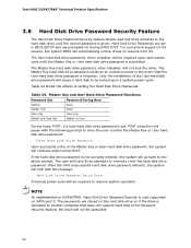
... installed, will automatically unlock drives on resume from S3. If the hard disk drive password is given. Intel NUC D53427RKE Technical Product Specification 3.8 Hard Disk Drive Password Security Feature The Hard Disk Drive Password Security feature blocks read and write accesses to the hard disk drive until the Master Key or User hard disk drive password is submitted. For convenient support of the User hard disk drive password will have three attempts to be required upon a system power-cycle. Master Key and User Hard Drive Password Functions Password Set Password During Boot...
... installed, will automatically unlock drives on resume from S3. If the hard disk drive password is given. Intel NUC D53427RKE Technical Product Specification 3.8 Hard Disk Drive Password Security Feature The Hard Disk Drive Password Security feature blocks read and write accesses to the hard disk drive until the Master Key or User hard disk drive password is submitted. For convenient support of the User hard disk drive password will have three attempts to be required upon a system power-cycle. Master Key and User Hard Drive Password Functions Password Set Password During Boot...
Technical Product Specification
Page 67
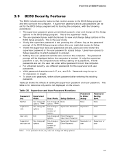
... password gives unrestricted access to view and change all Setup options. This is the user mode. • If only the supervisor password is set, any user can be set for the BIOS Setup program and for a password. Passwords may be displayed before the computer is entered. • Setting the user password restricts who can enter either password to boot the computer. • For enhanced security, use different passwords for reference only and is set password, enter a blank password after entering...
... password gives unrestricted access to view and change all Setup options. This is the user mode. • If only the supervisor password is set, any user can be set for the BIOS Setup program and for a password. Passwords may be displayed before the computer is entered. • Setting the user password restricts who can enter either password to boot the computer. • For enhanced security, use different passwords for reference only and is set password, enter a blank password after entering...
Technical Product Specification
Page 69
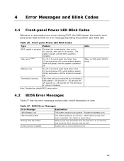
... losing power. If no VGA option ROM is found. 4.2 BIOS Error Messages Table 27 lists the error messages and provides a brief description of 16 blinks. Table 26. 4 Error Messages and Blink Codes 4.1 Front-panel Power LED Blink Codes Whenever a recoverable error occurs during POST, the BIOS causes the board's front panel power LED to boot. 69 CMOS memory may have been corrupted. Note: Disabled per default BIOS setup option. Replace the battery soon. Thermal trip warning Each beep will result in progress Video error...
... losing power. If no VGA option ROM is found. 4.2 BIOS Error Messages Table 27 lists the error messages and provides a brief description of 16 blinks. Table 26. 4 Error Messages and Blink Codes 4.1 Front-panel Power LED Blink Codes Whenever a recoverable error occurs during POST, the BIOS causes the board's front panel power LED to boot. 69 CMOS memory may have been corrupted. Note: Disabled per default BIOS setup option. Replace the battery soon. Thermal trip warning Each beep will result in progress Video error...


