
Technical product specification
Page 8
... 3.2 BIOS Flash Memory Organization 62 3.3 Resource Configuration 62 3.3.1 PCI* Autoconfiguration 62 3.4 System Management BIOS (SMBIOS 63 3.5 Legacy USB Support 64 3.6 BIOS Updates 65 3.6.1 BIOS Recovery 65 3.6.2 Custom Splash Screen 66 3.7 Boot Options 66 3.7.1 Optical Drive Boot 66 3.7.2 Network Boot 66 3.7.3 Booting Without Attached Devices 67 3.7.4 Changing the Default Boot Device During POST 67 3.8 BIOS Security Features 68 4 Board Status and Error Messages 4.1 BIOS Beep Codes 69 4.2 Front-panel Power LED Blink Codes 70 4.3 BIOS Error Messages 70 4.4 Port 80h POST Codes...
... 3.2 BIOS Flash Memory Organization 62 3.3 Resource Configuration 62 3.3.1 PCI* Autoconfiguration 62 3.4 System Management BIOS (SMBIOS 63 3.5 Legacy USB Support 64 3.6 BIOS Updates 65 3.6.1 BIOS Recovery 65 3.6.2 Custom Splash Screen 66 3.7 Boot Options 66 3.7.1 Optical Drive Boot 66 3.7.2 Network Boot 66 3.7.3 Booting Without Attached Devices 67 3.7.4 Changing the Default Boot Device During POST 67 3.8 BIOS Security Features 68 4 Board Status and Error Messages 4.1 BIOS Beep Codes 69 4.2 Front-panel Power LED Blink Codes 70 4.3 BIOS Error Messages 70 4.4 Port 80h POST Codes...
Technical product specification
Page 9
... LAN Connector LED Locations 24 5. Back Panel Audio Connectors 26 6. Location of the BIOS Configuration Jumper Block 50 16. Back Panel Connectors 39 10. Connection Diagram for AC '97 Audio 43 16. Location of the Standby Power Indicator LED 34 8. Wake-up Devices and Events 31 9. SATA Connectors 43 13. Front Panel Audio Header for Front Panel USB Header 49 14. Front Panel USB Header 44 17. Front Panel USB Header with Intel Z-USB Solid-State Drive or Compatible Device Support 49 15. Detailed System Memory Address Map 36 9. Connection Diagram for a One-Color Power LED...
... LAN Connector LED Locations 24 5. Back Panel Audio Connectors 26 6. Location of the BIOS Configuration Jumper Block 50 16. Back Panel Connectors 39 10. Connection Diagram for AC '97 Audio 43 16. Location of the Standby Power Indicator LED 34 8. Wake-up Devices and Events 31 9. SATA Connectors 43 13. Front Panel Audio Header for Front Panel USB Header 49 14. Front Panel USB Header 44 17. Front Panel USB Header with Intel Z-USB Solid-State Drive or Compatible Device Support 49 15. Detailed System Memory Address Map 36 9. Connection Diagram for a One-Color Power LED...
Technical product specification
Page 10
.... Fan Header Current Capability 53 23. Port 80h POST Code Ranges 71 36. EMC Regulations 81 40. Maximum Load Configuration Current and Power Results 59 26. Acceptable Drives/Media Types for Components 55 24. Regulatory Compliance Marks 85 x Front-panel Power LED Blink Codes 70 34. BIOS Setup Program Function Keys 62 29. Port 80h POST Codes 72 37. BIOS Beep Codes 69 33. Intel Desktop Board D2550DC2 Technical Product Specification 21. Minimum Load Configuration Current and Power Results 58 25. Boot Device Menu Options...
.... Fan Header Current Capability 53 23. Port 80h POST Code Ranges 71 36. EMC Regulations 81 40. Maximum Load Configuration Current and Power Results 59 26. Acceptable Drives/Media Types for Components 55 24. Regulatory Compliance Marks 85 x Front-panel Power LED Blink Codes 70 34. BIOS Setup Program Function Keys 62 29. Port 80h POST Codes 72 37. BIOS Beep Codes 69 33. Intel Desktop Board D2550DC2 Technical Product Specification 21. Minimum Load Configuration Current and Power Results 58 25. Boot Device Menu Options...
Technical product specification
Page 11
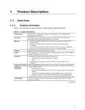
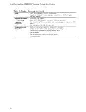
...; Seven USB 2.0 ports: ― Four back panel ports ― Two ports are implemented with a dual port internal header for front panel cabling ― One port is implemented with an internal header (brown-colored) that supports an Intel® Z-U130 USB Solid-State Drive or compatible device • Two Serial ATA (SATA) 3.0 Gb/s connectors (supporting IDE and AHCI mode) 10/100/1000 Mb/s Ethernet LAN subsystem using an Intel® 82574L Gigabit Ethernet Controller continued 11 Table 1. Feature Summary Form Factor Processor Memory Chipset Audio Graphics Legacy I/O Control Peripheral...
...; Seven USB 2.0 ports: ― Four back panel ports ― Two ports are implemented with a dual port internal header for front panel cabling ― One port is implemented with an internal header (brown-colored) that supports an Intel® Z-U130 USB Solid-State Drive or compatible device • Two Serial ATA (SATA) 3.0 Gb/s connectors (supporting IDE and AHCI mode) 10/100/1000 Mb/s Ethernet LAN subsystem using an Intel® 82574L Gigabit Ethernet Controller continued 11 Table 1. Feature Summary Form Factor Processor Memory Chipset Audio Graphics Legacy I/O Control Peripheral...
Technical product specification
Page 12
...; One Conventional PCI bus connector (with riser card support for up to two PCI cards) • One PCI Express Full-/Half-Mini Card slot Hardware Monitor Subsystem • Hardware monitoring through the Windbond I/O controller • Voltage sense to detect out of range power supply voltages • Thermal sense to detect out of range thermal values • One fan header • One fan sense input used to monitor fan activity • Fan speed control 12 Intel Desktop Board D2550DC2 Technical Product Specification Table 1.
...; One Conventional PCI bus connector (with riser card support for up to two PCI cards) • One PCI Express Full-/Half-Mini Card slot Hardware Monitor Subsystem • Hardware monitoring through the Windbond I/O controller • Voltage sense to detect out of range power supply voltages • Thermal sense to detect out of range thermal values • One fan header • One fan sense input used to monitor fan activity • Fan speed control 12 Intel Desktop Board D2550DC2 Technical Product Specification Table 1.
Technical product specification
Page 16
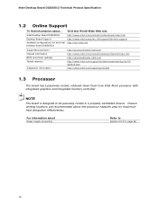
...recommended above the processor heatsink area for the Intel http://ark.intel.com Desktop Board D2550DC2 Supported processors Chipset information BIOS and driver updates Tested memory Integration information http://processormatch.intel.com http://www.intel.com/products/desktop/chipsets/index.htm http://downloadcenter.intel.com http://www.intel.com/support/motherboards/desktop/sb/CS025414.htm http://www.intel.com/support/go/buildit 1.3 Processor The board has a passively-cooled, soldered-down Dual-Core Intel Atom processor with integrated graphics and integrated memory controller. Visit this...
...recommended above the processor heatsink area for the Intel http://ark.intel.com Desktop Board D2550DC2 Supported processors Chipset information BIOS and driver updates Tested memory Integration information http://processormatch.intel.com http://www.intel.com/products/desktop/chipsets/index.htm http://downloadcenter.intel.com http://www.intel.com/support/motherboards/desktop/sb/CS025414.htm http://www.intel.com/support/go/buildit 1.3 Processor The board has a passively-cooled, soldered-down Dual-Core Intel Atom processor with integrated graphics and integrated memory controller. Visit this...
Technical product specification
Page 18
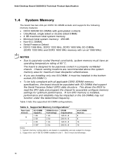
System memory configurations are based on availability and are installing only one 4 GB SO-DIMM installed in a properly ventilated chassis. Supported Memory Configurations1 Raw Card Version SO-DIMM Capacity DRAM Device DRAM Technology Organization # of 85 oC. Slot 0 must be impacted or the SO-DIMMs may be left empty. 18 Intel Desktop Board D2550DC2 Technical Product Specification 1.4 System Memory The board has two 204-pin DDR3 SO-DIMM sockets and supports the following memory features: •...
System memory configurations are based on availability and are installing only one 4 GB SO-DIMM installed in a properly ventilated chassis. Supported Memory Configurations1 Raw Card Version SO-DIMM Capacity DRAM Device DRAM Technology Organization # of 85 oC. Slot 0 must be impacted or the SO-DIMMs may be left empty. 18 Intel Desktop Board D2550DC2 Technical Product Specification 1.4 System Memory The board has two 204-pin DDR3 SO-DIMM sockets and supports the following memory features: •...
Technical product specification
Page 36
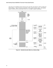
Detailed System Memory Address Map 36 Figure 8 shows a schematic of system addresses. Intel Desktop Board D2550DC2 Technical Product Specification The amount of installed memory that can be used when there is no overlap of the system memory map. All installed system memory can be used will vary based on add-in cards and BIOS settings. Figure 8.
Detailed System Memory Address Map 36 Figure 8 shows a schematic of system addresses. Intel Desktop Board D2550DC2 Technical Product Specification The amount of installed memory that can be used when there is no overlap of the system memory map. All installed system memory can be used will vary based on add-in cards and BIOS settings. Figure 8.

Technical product specification
Page 49
Connection Diagram for high-speed USB devices. Figure 13. NOTE • The +5 VDC power on the USB headers is fused. • Use only a front panel USB connector that conforms to the USB 2.0 specification for Front Panel USB Header Figure 14. Connection Diagram for the front panel USB headers. Technical Reference 2.2.2.5 Front Panel USB Headers Figure 13 and Figure 14 are connection diagrams for Front Panel USB Header with Intel Z-USB Solid-State Drive or Compatible Device Support 49
Connection Diagram for high-speed USB devices. Figure 13. NOTE • The +5 VDC power on the USB headers is fused. • Use only a front panel USB connector that conforms to the USB 2.0 specification for Front Panel USB Header Figure 14. Connection Diagram for the front panel USB headers. Technical Reference 2.2.2.5 Front Panel USB Headers Figure 13 and Figure 14 are connection diagrams for Front Panel USB Header with Intel Z-USB Solid-State Drive or Compatible Device Support 49

Technical product specification
Page 61
... menu bar is accessed by pressing the key after the Power-On Self-Test (POST) memory test begins and before the operating system boot begins. Section 2.3 on page 50 shows how to view and change the BIOS settings for the computer. The SPI Flash contains the BIOS Setup program, POST, the PCI auto-configuration utility, LAN EEPROM information, and Plug and Play support. The BIOS Setup program can be used to put the board in configure mode...
... menu bar is accessed by pressing the key after the Power-On Self-Test (POST) memory test begins and before the operating system boot begins. Section 2.3 on page 50 shows how to view and change the BIOS settings for the computer. The SPI Flash contains the BIOS Setup program, POST, the PCI auto-configuration utility, LAN EEPROM information, and Plug and Play support. The BIOS Setup program can be used to put the board in configure mode...
Technical product specification
Page 62
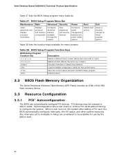
... 28 lists the function keys available for menu screens. Any interrupts set to Available in Setup are considered to be onboard or add-in card. 62 Table 27. BIOS Setup Program Menu Bar Maintenance Main Advanced Security Clears passwords and displays processor information Displays processor and memory configuration Configures advanced features available through the chipset Sets passwords and security features Power Boot Configures power management features and power states options Selects boot options Exit Saves or discards changes to configure the system. PCI devices may...
... 28 lists the function keys available for menu screens. Any interrupts set to Available in Setup are considered to be onboard or add-in card. 62 Table 27. BIOS Setup Program Menu Bar Maintenance Main Advanced Security Clears passwords and displays processor information Displays processor and memory configuration Configures advanced features available through the chipset Sets passwords and security features Power Boot Configures power management features and power states options Selects boot options Exit Saves or discards changes to configure the system. PCI devices may...

Technical product specification
Page 70
... 33). Memory size has decreased since the last boot. Intel Desktop Board D2550DC2 Technical Product Specification 4.2 Front-panel Power LED Blink Codes Whenever a recoverable error occurs during POST, the BIOS displays an error message describing the problem. Table 34. BIOS Error Messages Error Message Explanation CMOS Battery Low CMOS Checksum Bad Memory Size Decreased No Boot Device Available The battery may have been corrupted. Run Setup to boot. 70 Note: Disabled per default BIOS setup option. System did not find a device to reset values. Table 33. Memory error On...
... 33). Memory size has decreased since the last boot. Intel Desktop Board D2550DC2 Technical Product Specification 4.2 Front-panel Power LED Blink Codes Whenever a recoverable error occurs during POST, the BIOS displays an error message describing the problem. Table 34. BIOS Error Messages Error Message Explanation CMOS Battery Low CMOS Checksum Bad Memory Size Decreased No Boot Device Available The battery may have been corrupted. Run Setup to boot. 70 Note: Disabled per default BIOS setup option. System did not find a device to reset values. Table 33. Memory error On...

Technical product specification
Page 71
... use For future use Input devices: Keyboard/Mouse. NOTE The POST card must be up at port 80h. Table 35. S3, etc.) PEI phase pre MRC execution MRC memory detection PEI phase post MRC execution Recovery Platform DXE driver CPU Initialization (PEI, DXE, SMM) I /O port 80h. For future use Boot Devices: Includes fixed media and removable media. Board Status and Error Messages 4.4 Port 80h POST Codes During the POST, the BIOS generates diagnostic progress codes (POST codes...
... use For future use Input devices: Keyboard/Mouse. NOTE The POST card must be up at port 80h. Table 35. S3, etc.) PEI phase pre MRC execution MRC memory detection PEI phase post MRC execution Recovery Platform DXE driver CPU Initialization (PEI, DXE, SMM) I /O port 80h. For future use Boot Devices: Includes fixed media and removable media. Board Status and Error Messages 4.4 Port 80h POST Codes During the POST, the BIOS generates diagnostic progress codes (POST codes...

Product guide for Intel Desktop Board D2550DC2
Page 5
... and Removing Memory 28 Connecting SATA Drives 29 Installing a PCI Express Mini Card 30 Installing an Intel® Z-U130 USB Solid-State Drive or Compatible Device 32 Connecting to the Internal Headers 33 Connecting to the Front Panel Audio Header 34 Connecting to the Front Panel USB 2.0 Headers 35 Connecting to the Piezoelectric Speaker Header 35 Connecting to the Front Panel Header 36 Connecting to the Front Panel Wireless Activity LED Header 36 Connecting a System Fan 37 Connecting a Power Supply 38 Setting the BIOS Configuration Jumper 39 Clearing Passwords 40 Replacing the...
... and Removing Memory 28 Connecting SATA Drives 29 Installing a PCI Express Mini Card 30 Installing an Intel® Z-U130 USB Solid-State Drive or Compatible Device 32 Connecting to the Internal Headers 33 Connecting to the Front Panel Audio Header 34 Connecting to the Front Panel USB 2.0 Headers 35 Connecting to the Piezoelectric Speaker Header 35 Connecting to the Front Panel Header 36 Connecting to the Front Panel Wireless Activity LED Header 36 Connecting a System Fan 37 Connecting a Power Supply 38 Setting the BIOS Configuration Jumper 39 Clearing Passwords 40 Replacing the...

Product guide for Intel Desktop Board D2550DC2
Page 18
...; One PCI bus connector. The SATA controller supports IDE and ACHI configuration and can support either a single PCI add-in the BIOS automatically detects and configures the resources (IRQs, DMA channels, and I/O space) for a full-speed USB device. The connector can operate in both an operating system and drivers that add-in card. 18 One of the front panel USB headers supports an Intel Z-U130 USB Solid-State Drive or compatible device. PCI/PCI Express Auto Configuration If you install a PCI/PCI Express add-in card. NOTE Computer...
...; One PCI bus connector. The SATA controller supports IDE and ACHI configuration and can support either a single PCI add-in the BIOS automatically detects and configures the resources (IRQs, DMA channels, and I/O space) for a full-speed USB device. The connector can operate in both an operating system and drivers that add-in card. 18 One of the front panel USB headers supports an Intel Z-U130 USB Solid-State Drive or compatible device. PCI/PCI Express Auto Configuration If you install a PCI/PCI Express add-in card. NOTE Computer...
Product guide for Intel Desktop Board D2550DC2
Page 19
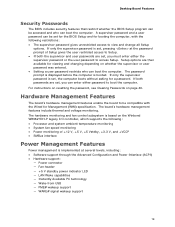
... can enter either the supervisor password or the user password to view and change all Setup options. For instructions on resetting the password, see Clearing Passwords on page 40. The password prompt is displayed before the computer is set, pressing at several levels, including: • Software support through the Advanced Configuration and Power Interface (ACPI) • Hardware support: ― Power connector ― Fan header ― +5 V standby power indicator LED ― LAN Wake capabilities ― Instantly Available PC technology ― Wake from USB...
... can enter either the supervisor password or the user password to view and change all Setup options. For instructions on resetting the password, see Clearing Passwords on page 40. The password prompt is displayed before the computer is set, pressing at several levels, including: • Software support through the Advanced Configuration and Power Interface (ACPI) • Hardware support: ― Power connector ― Fan header ― +5 V standby power indicator LED ― LAN Wake capabilities ― Instantly Available PC technology ― Wake from USB...
Product guide for Intel Desktop Board D2550DC2
Page 40
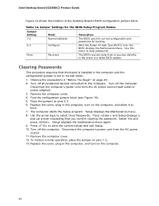
... jumper on pins 1-2. 13. Replace the cover, plug in the event of the Desktop Board's BIOS configuration jumper block. Use the arrow keys to normal mode. 1. Select Yes and press . To restore normal operation, place the jumper on pins 2-3. 6. Clearing Passwords This procedure assumes that you confirm clearing the password. The computer starts the Setup program. Turn off the computer. Turn off the computer. Remove the computer cover. 4. Setup displays the Maintenance menu. 8. Disconnect the computer's power...
... jumper on pins 1-2. 13. Replace the cover, plug in the event of the Desktop Board's BIOS configuration jumper block. Use the arrow keys to normal mode. 1. Select Yes and press . To restore normal operation, place the jumper on pins 2-3. 6. Clearing Passwords This procedure assumes that you confirm clearing the password. The computer starts the Setup program. Turn off the computer. Turn off the computer. Remove the computer cover. 4. Setup displays the Maintenance menu. 8. Disconnect the computer's power...

Product guide for Intel Desktop Board D2550DC2
Page 47
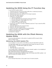
... the D2550DC2 page. This chapter tells you how to update the BIOS by pressing the key after the Power-On Self-Test (POST) memory test begins and before the operating system boot begins. Click on your hard drive. (You can access the BIOS Setup program by either using the Intel Express BIOS Update utility or the Iflash Memory Update utility, and how to complete the BIOS update. 47 This step is included in the Windows...
... the D2550DC2 page. This chapter tells you how to update the BIOS by pressing the key after the Power-On Self-Test (POST) memory test begins and before the operating system boot begins. Click on your hard drive. (You can access the BIOS Setup program by either using the Intel Express BIOS Update utility or the Iflash Memory Update utility, and how to complete the BIOS update. 47 This step is included in the Windows...
Product guide for Intel Desktop Board D2550DC2
Page 48
... Intel Desktop D2550DC2 page, click "[view] Latest BIOS updates," and select the Iflash BIOS Update utility file. Enable Display F7 to a new version of the BIOS by pressing Enter. 10. Select the USB thumb drive and press Enter. 8. Obtaining the BIOS Update File You can update to Update BIOS e. Download and save and exit. 6. Copy the .BIO file to a temporary directory. 2. Plug the thumb drive into a USB port of these files through your computer supplier or by pressing the F2 key during boot. b. c. Remove...
... Intel Desktop D2550DC2 page, click "[view] Latest BIOS updates," and select the Iflash BIOS Update utility file. Enable Display F7 to a new version of the BIOS by pressing Enter. 10. Select the USB thumb drive and press Enter. 8. Obtaining the BIOS Update File You can update to Update BIOS e. Download and save and exit. 6. Copy the .BIO file to a temporary directory. 2. Plug the thumb drive into a USB port of these files through your computer supplier or by pressing the F2 key during boot. b. c. Remove...
Product guide for Intel Desktop Board D2550DC2
Page 49
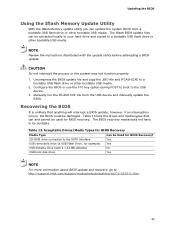
... to your hard drive and copied to the SATA interface USB removable drive (a USB Flash Drive, for example) USB diskette drive (with the update utility before attempting a BIOS update. CAUTION Do not interrupt the process or the system may not function properly. 1. Acceptable Drives/Media Types for BIOS recovery. Uncompress the BIOS update file and copy the .BIO file and IFLASH.EXE to the USB device. 3. Configure the BIOS or use the F10 key option during POST to boot to a bootable USB flash drive or other...
... to your hard drive and copied to the SATA interface USB removable drive (a USB Flash Drive, for example) USB diskette drive (with the update utility before attempting a BIOS update. CAUTION Do not interrupt the process or the system may not function properly. 1. Acceptable Drives/Media Types for BIOS recovery. Uncompress the BIOS update file and copy the .BIO file and IFLASH.EXE to the USB device. 3. Configure the BIOS or use the F10 key option during POST to boot to a bootable USB flash drive or other...


