Product Guide
Page 3
... beep codes B Regulatory Compliance: safety and EMC regulations and product certifications Conventions The following conventions are arranged as Information Technology Equipment (I.T.E.) for use in personal computers (PC) for Intel® Desktop Board D410PT. Intended Audience The Product Guide is not intended for general audiences. Intended Uses All Intel® Desktop Boards are evaluated as follows: 1 Desktop Board Features: a summary of product features 2 Installing and Replacing Desktop Board Components: instructions...
... beep codes B Regulatory Compliance: safety and EMC regulations and product certifications Conventions The following conventions are arranged as Information Technology Equipment (I.T.E.) for use in personal computers (PC) for Intel® Desktop Board D410PT. Intended Audience The Product Guide is not intended for general audiences. Intended Uses All Intel® Desktop Boards are evaluated as follows: 1 Desktop Board Features: a summary of product features 2 Installing and Replacing Desktop Board Components: instructions...
Product Guide
Page 5
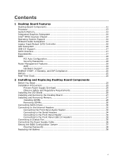
Contents 1 Desktop Board Features Desktop Board Components 11 Processor ...13 System Memory 13 Integrated Graphics Subsystem 14 Intel® NM10 Express Chipset 14 Operating System Support 14 Onboard Audio Subsystem 14 Legacy Input/Output (I/O) Controller 16 LAN Subsystem 16 USB 2.0 Support 17 SATA Interface 17 Expandability...17 BIOS ...18 PCI Auto Configuration 18 Security Passwords 18 Power Management Features 18 ACPI ...19 Hardware Support 19 ENERGY STAR*, e-Standby, and ErP Compliance 22 Battery ...22 Real-Time Clock 22 2 Installing and Replacing Desktop Board Components...
Contents 1 Desktop Board Features Desktop Board Components 11 Processor ...13 System Memory 13 Integrated Graphics Subsystem 14 Intel® NM10 Express Chipset 14 Operating System Support 14 Onboard Audio Subsystem 14 Legacy Input/Output (I/O) Controller 16 LAN Subsystem 16 USB 2.0 Support 17 SATA Interface 17 Expandability...17 BIOS ...18 PCI Auto Configuration 18 Security Passwords 18 Power Management Features 18 ACPI ...19 Hardware Support 19 ENERGY STAR*, e-Standby, and ErP Compliance 22 Battery ...22 Real-Time Clock 22 2 Installing and Replacing Desktop Board Components...
Product Guide
Page 6
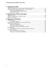
Intel Desktop Board D410PT Product Guide 3 Updating the BIOS Updating the BIOS with the Intel® Express BIOS Update Utility 45 Updating the BIOS with the Iflash Memory Update Utility 46 Obtaining the BIOS Update File 46 Using the Iflash Memory Update Utility 46 Recovering the BIOS 47 A Board Status and Error Messages BIOS Beep Codes 49 BIOS Front-panel Power LED Blink Codes 50 POST Error Messages 50 B Regulatory Compliance Safety Standards 51 Place Battery Marking 51 European Union Declaration of Conformity Statement 52 Product Ecology Statements 53 Recycling...
Intel Desktop Board D410PT Product Guide 3 Updating the BIOS Updating the BIOS with the Intel® Express BIOS Update Utility 45 Updating the BIOS with the Iflash Memory Update Utility 46 Obtaining the BIOS Update File 46 Using the Iflash Memory Update Utility 46 Recovering the BIOS 47 A Board Status and Error Messages BIOS Beep Codes 49 BIOS Front-panel Power LED Blink Codes 50 POST Error Messages 50 B Regulatory Compliance Safety Standards 51 Place Battery Marking 51 European Union Declaration of Conformity Statement 52 Product Ecology Statements 53 Recycling...

Product Guide
Page 7
... Support 15 4. LAN Status LEDs 17 5. Front Panel Audio Header for BIOS Recovery 47 13. Front Panel USB Header 35 11. Lead-Free Second Level Interconnect Marks 56 18. EMC Regulations 59 20. Intel Desktop Board D410PT Components 11 2. Installing the I/O Shield 26 6. Use DDR2 DIMMs 28 8. Acceptable Drives/Media Types for Intel HD Audio 33 7. POST Error Messages 50 16. China RoHS Environmentally Friendly Use Period Mark 57 19. LAN Status LEDs 16 4. BIOS Beep Codes 49 14. Intel Desktop Board...
... Support 15 4. LAN Status LEDs 17 5. Front Panel Audio Header for BIOS Recovery 47 13. Front Panel USB Header 35 11. Lead-Free Second Level Interconnect Marks 56 18. EMC Regulations 59 20. Intel Desktop Board D410PT Components 11 2. Installing the I/O Shield 26 6. Use DDR2 DIMMs 28 8. Acceptable Drives/Media Types for Intel HD Audio 33 7. POST Error Messages 50 16. China RoHS Environmentally Friendly Use Period Mark 57 19. LAN Status LEDs 16 4. BIOS Beep Codes 49 14. Intel Desktop Board...
Product Guide
Page 9
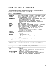
... 3-pin chassis fan header with support for analog displays (VGA) Realtek* ALC662 audio codec for Advanced Configuration and Power Interface (ACPI) • Wake on USB, PCI, PS/2, LAN, serial, and front panel 9 Table 1. 1 Desktop Board Features This chapter briefly describes the main features of the Desktop Board. Table 1 summarizes the features of Intel® Desktop Board D410PT. Included are: • Back panel connectors • Front panel microphone/headphone header with support for Intel® HD Audio or AC '97 Audio One PCI* bus add-in card connector...
... 3-pin chassis fan header with support for analog displays (VGA) Realtek* ALC662 audio codec for Advanced Configuration and Power Interface (ACPI) • Wake on USB, PCI, PS/2, LAN, serial, and front panel 9 Table 1. 1 Desktop Board Features This chapter briefly describes the main features of the Desktop Board. Table 1 summarizes the features of Intel® Desktop Board D410PT. Included are: • Back panel connectors • Front panel microphone/headphone header with support for Intel® HD Audio or AC '97 Audio One PCI* bus add-in card connector...
Product Guide
Page 13
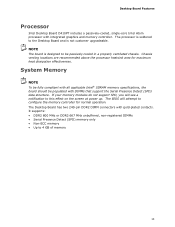
Desktop Board Features Processor Intel Desktop Board D410PT includes a passively-cooled, single-core Intel Atom processor with gold-plated contacts. Chassis venting locations are recommended above the processor heatsink area for normal operation. System Memory NOTE To be fully compliant with DIMMs that support the Serial Presence Detect (SPD) data structure. The Desktop Board has two 240-pin DDR2 DIMM connectors with integrated graphics and memory controller. It supports: • DDR2 800 MHz or DDR2...
Desktop Board Features Processor Intel Desktop Board D410PT includes a passively-cooled, single-core Intel Atom processor with gold-plated contacts. Chassis venting locations are recommended above the processor heatsink area for normal operation. System Memory NOTE To be fully compliant with DIMMs that support the Serial Presence Detect (SPD) data structure. The Desktop Board has two 240-pin DDR2 DIMM connectors with integrated graphics and memory controller. It supports: • DDR2 800 MHz or DDR2...

Product Guide
Page 16
...; Intel NM10 Express Chipset • Realtek RTL8103EL Ethernet Controller for 10/100 Mbits/s Ethernet LAN connectivity • RJ-45 LAN connector with serialized IRQ support for PCI systems • PS/2-style keyboard and mouse ports • Intelligent power management, including a programmable wake up event interface • PCI power management support The BIOS Setup program provides configuration options for the legacy I/O controller. LAN Subsystem The LAN subsystem consists of the following : • Two serial ports (via onboard headers) • Serial IRQ interface compatible...
...; Intel NM10 Express Chipset • Realtek RTL8103EL Ethernet Controller for 10/100 Mbits/s Ethernet LAN connectivity • RJ-45 LAN connector with serialized IRQ support for PCI systems • PS/2-style keyboard and mouse ports • Intelligent power management, including a programmable wake up event interface • PCI power management support The BIOS Setup program provides configuration options for the legacy I/O controller. LAN Subsystem The LAN subsystem consists of the following : • Two serial ports (via onboard headers) • Serial IRQ interface compatible...
Product Guide
Page 17
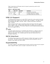
..., even if no device or a low-speed USB device is attached to USB 1.1 operation. The SATA controller supports IDE and ACHI configuration and can support either a single PCI add-in the BIOS reverts all USB 2.0 ports to the cable. USB 2.0 support requires both legacy and native modes. or dual-slot PCI riser card. 17 USB 2.0 Support The Desktop Board supports up and the LAN subsystem is selected. Use a shielded cable that fully support USB 2.0 transfer rates. LAN Status LEDs LED Activity (A) Speed (B) LED Color Green N/A Yellow LED State Blinking Off...
..., even if no device or a low-speed USB device is attached to USB 1.1 operation. The SATA controller supports IDE and ACHI configuration and can support either a single PCI add-in the BIOS reverts all USB 2.0 ports to the cable. USB 2.0 support requires both legacy and native modes. or dual-slot PCI riser card. 17 USB 2.0 Support The Desktop Board supports up and the LAN subsystem is selected. Use a shielded cable that fully support USB 2.0 transfer rates. LAN Status LEDs LED Activity (A) Speed (B) LED Color Green N/A Yellow LED State Blinking Off...

Product Guide
Page 18
... support: ― Power connector ― Fan header ― +5 V standby power indicator LED ― LAN Wake capabilities ― Instantly Available PC technology ― Wake from USB ― Wake from PS/2 devices ― PME# wakeup support ― Wake from serial port 18 You do not need to run the BIOS Setup program after you must enter either password to view and change all Setup options. Intel Desktop Board D410PT Product Guide BIOS The BIOS provides the Power-On Self-Test (POST), the BIOS Setup program, the PCI and IDE auto-configuration utilities...
... support: ― Power connector ― Fan header ― +5 V standby power indicator LED ― LAN Wake capabilities ― Instantly Available PC technology ― Wake from USB ― Wake from PS/2 devices ― PME# wakeup support ― Wake from serial port 18 You do not need to run the BIOS Setup program after you must enter either password to view and change all Setup options. Intel Desktop Board D410PT Product Guide BIOS The BIOS provides the Power-On Self-Test (POST), the BIOS Setup program, the PCI and IDE auto-configuration utilities...
Product Guide
Page 19
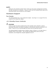
... any devices connected to the system. This includes the DIMM socket and the PCI bus connector, even though the computer appears to be off and the standby power indicator is standby power to the board. See Figure 11 on page 35 for the location of the chassis fan header. +5 V Standby Power Indicator CAUTION If the AC power has been switched off . 19 Hardware Support Fan Header The Desktop Board has a 3-pin chassis fan header. The use...
... any devices connected to the system. This includes the DIMM socket and the PCI bus connector, even though the computer appears to be off and the standby power indicator is standby power to the board. See Figure 11 on page 35 for the location of the chassis fan header. +5 V Standby Power Indicator CAUTION If the AC power has been switched off . 19 Hardware Support Fan Header The Desktop Board has a 3-pin chassis fan header. The use...

Product Guide
Page 20
... information on the Intel Desktop D410PT web page at http://www.intel.com/products/motherboard/D410PT/index.htm. When signaled by a wake-up device or event, the system quickly returns to enter the ACPI S3 (Suspend-toRAM) sleep-state. The board supports the PCI Bus Power Management Interface Specification. Add-in boards that also support this specification can be off (the hard drive(s) and fan will power off, the front panel power LED will appear...
... information on the Intel Desktop D410PT web page at http://www.intel.com/products/motherboard/D410PT/index.htm. When signaled by a wake-up device or event, the system quickly returns to enter the ACPI S3 (Suspend-toRAM) sleep-state. The board supports the PCI Bus Power Management Interface Specification. Add-in boards that also support this specification can be off (the hard drive(s) and fan will power off, the front panel power LED will appear...
Product Guide
Page 23
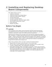
... front panel power button is not available, you can damage components. 2 Installing and Replacing Desktop Board Components This chapter tells you how to: • Install the I/O shield • Install and remove the Desktop Board • Install and remove system memory • Connect SATA drives • Connect to internal headers • Connect chassis fan and power supply cables • Set the BIOS configuration jumper • Clear passwords • Replace the battery Before You Begin CAUTION The procedures in this chapter only at an ESD workstation using and...
... front panel power button is not available, you can damage components. 2 Installing and Replacing Desktop Board Components This chapter tells you how to: • Install the I/O shield • Install and remove the Desktop Board • Install and remove system memory • Connect SATA drives • Connect to internal headers • Connect chassis fan and power supply cables • Set the BIOS configuration jumper • Clear passwords • Replace the battery Before You Begin CAUTION The procedures in this chapter only at an ESD workstation using and...
Product Guide
Page 29
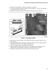
... the computer. Remove the computer's cover and locate the DIMM socket (see Figure 8). 6. Align the small notch at either end of the DIMM into place. Make sure the clips at the bottom edge of the DIMM until the retaining clips snap into the socket. 7. Installing a DIMM 4. Turn off all peripheral devices connected to the open position. 5. Replace the computer...
... the computer. Remove the computer's cover and locate the DIMM socket (see Figure 8). 6. Align the small notch at either end of the DIMM into place. Make sure the clips at the bottom edge of the DIMM until the retaining clips snap into the socket. 7. Installing a DIMM 4. Turn off all peripheral devices connected to the open position. 5. Replace the computer...
Product Guide
Page 30
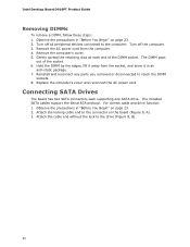
... the connector on the board (Figure 9, A). 3. Gently spread the retaining clips at each supporting one SATA drive. Remove the AC power cord from the socket, and store it in "Before You Begin" on page 23. 2. Reinstall and reconnect any parts you removed or disconnected to the computer. The included SATA cables support the Serial ATA protocol. Intel Desktop Board D410PT Product Guide Removing DIMMs To remove a DIMM, follow these steps: 1. Turn...
... the connector on the board (Figure 9, A). 3. Gently spread the retaining clips at each supporting one SATA drive. Remove the AC power cord from the socket, and store it in "Before You Begin" on page 23. 2. Reinstall and reconnect any parts you removed or disconnected to the computer. The included SATA cables support the Serial ATA protocol. Intel Desktop Board D410PT Product Guide Removing DIMMs To remove a DIMM, follow these steps: 1. Turn...
Product Guide
Page 33
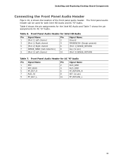
... AC '97 Audio. The front panel audio header can be used for AC '97 Audio. Installing and Replacing Desktop Board Components Connecting the Front Panel Audio Header Figure 10, A shows the location of the front panel audio header. Front Panel Audio Header for AC '97 Audio Pin Signal Name 1 MIC 3 MIC_BIAS 5 FP_OUT_R 7 AUD_5V 9 FP_OUT_L Pin Signal Name 2 AUD_GND 4 AUD_GND 6 FP_RETURN_R 8 KEY (no pin) [Port 2] SENSE_RETURN Table 7. Table 6. Front Panel Audio Header for Intel HD Audio Pin Signal Name 1 [Port 1] Left channel 3 [Port 1] Right channel Pin Signal...
... AC '97 Audio. The front panel audio header can be used for AC '97 Audio. Installing and Replacing Desktop Board Components Connecting the Front Panel Audio Header Figure 10, A shows the location of the front panel audio header. Front Panel Audio Header for AC '97 Audio Pin Signal Name 1 MIC 3 MIC_BIAS 5 FP_OUT_R 7 AUD_5V 9 FP_OUT_L Pin Signal Name 2 AUD_GND 4 AUD_GND 6 FP_RETURN_R 8 KEY (no pin) [Port 2] SENSE_RETURN Table 7. Table 6. Front Panel Audio Header for Intel HD Audio Pin Signal Name 1 [Port 1] Left channel 3 [Port 1] Right channel Pin Signal...

Product Guide
Page 38
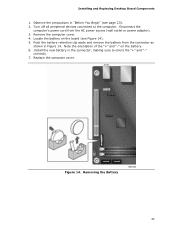
... it to normal mode. 1. Select Yes and press . Press to the computer. Remove the computer cover. 38 Intel Desktop Board D410PT Product Guide Table 11. Setup displays the Maintenance menu. 8. Find the configuration jumper block (see Figure 13, B). 5. Replace the cover, plug in "Before You Begin" on page 23. 2. Configure (2-3) After the Power-On Self-Test (POST) runs, the BIOS displays the Maintenance Menu. Turn off all peripheral devices connected to save...
... it to normal mode. 1. Select Yes and press . Press to the computer. Remove the computer cover. 38 Intel Desktop Board D410PT Product Guide Table 11. Setup displays the Maintenance menu. 8. Find the configuration jumper block (see Figure 13, B). 5. Replace the cover, plug in "Before You Begin" on page 23. 2. Configure (2-3) After the Power-On Self-Test (POST) runs, the BIOS displays the Maintenance Menu. Turn off all peripheral devices connected to save...
Product Guide
Page 39
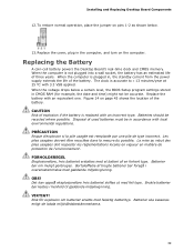
.... Replace the cover, plug in the computer, and turn on pins 1-2 as shown below a certain level, the BIOS Setup program settings stored in CMOS RAM (for example, the date and time) might not be in , the standby current from the power supply extends the life of the battery. When the computer is not plugged into a wall socket, the battery has an estimated life of used batteries must...
.... Replace the cover, plug in the computer, and turn on pins 1-2 as shown below a certain level, the BIOS Setup program settings stored in CMOS RAM (for example, the date and time) might not be in , the standby current from the power supply extends the life of the battery. When the computer is not plugged into a wall socket, the battery has an estimated life of used batteries must...
Product Guide
Page 43
...). 2. Install the new battery in the connector, making sure to the computer. Figure 14. Removing the Battery 43 Disconnect the computer's power cord from the connector as shown in "Before You Begin" (see Figure 14). 5. Push the battery retention clip aside and remove the battery from the AC power source (wall outlet or power adapter). 3. Replace the computer cover. Turn off all peripheral devices connected to...
...). 2. Install the new battery in the connector, making sure to the computer. Figure 14. Removing the Battery 43 Disconnect the computer's power cord from the connector as shown in "Before You Begin" (see Figure 14). 5. Push the battery retention clip aside and remove the battery from the AC power source (wall outlet or power adapter). 3. Replace the computer cover. Turn off all peripheral devices connected to...

Product Guide
Page 45
...://support.intel.com/support/motherboards/desktop/. 2. Double-click the executable file from the location on your hard drive. (You can be rebooted at the last Intel Express BIOS Update window. 5. Follow the instructions provided in an automated update utility that combines the functionality of the Intel® Flash Memory Update Utility and the ease of use of Windows-based installation wizards. To update the BIOS with the Intel® Express BIOS Update Utility With the Intel Express BIOS Update utility you can access the BIOS Setup program by either using the Intel Express BIOS...
...://support.intel.com/support/motherboards/desktop/. 2. Double-click the executable file from the location on your hard drive. (You can be rebooted at the last Intel Express BIOS Update window. 5. Follow the instructions provided in an automated update utility that combines the functionality of the Intel® Flash Memory Update Utility and the ease of use of Windows-based installation wizards. To update the BIOS with the Intel® Express BIOS Update Utility With the Intel Express BIOS Update utility you can access the BIOS Setup program by either using the Intel Express BIOS...
Product Guide
Page 46
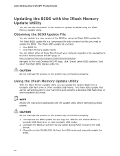
... Memory Update Utility With the Iflash Memory update utility you need to update the BIOS. Manually run the IFLASH.EXE file from a bootable USB flash drive or other bootable USB media. Obtaining the BIOS Update File You can update to a new version of these files through your hard drive and copied to update the BIOS using the Iflash BIOS update file. Uncompress the BIOS update file and copy the .BIO file and IFLASH.EXE to the Intel Desktop Board D410PT page at http://support.intel.com/support/motherboards/desktop. The Iflash BIOS update files...
... Memory Update Utility With the Iflash Memory update utility you need to update the BIOS. Manually run the IFLASH.EXE file from a bootable USB flash drive or other bootable USB media. Obtaining the BIOS Update File You can update to a new version of these files through your hard drive and copied to update the BIOS using the Iflash BIOS update file. Uncompress the BIOS update file and copy the .BIO file and IFLASH.EXE to the Intel Desktop Board D410PT page at http://support.intel.com/support/motherboards/desktop. The Iflash BIOS update files...


