
Product Guide
Page 3
... manual: CAUTION Cautions warn the user about configuring your system for installation in personal computers (PC) for RAID A Error Messages and Indicators: information about BIOS error messages and beep codes B Regulatory Compliance: describes the board's adherence to safety standards and EMC regulations and its product certifications Conventions The following conventions are arranged as follows: 1 Desktop Board Features: a summary of product features 2 Installing and Replacing Desktop Board Components: instructions...
... manual: CAUTION Cautions warn the user about configuring your system for installation in personal computers (PC) for RAID A Error Messages and Indicators: information about BIOS error messages and beep codes B Regulatory Compliance: describes the board's adherence to safety standards and EMC regulations and its product certifications Conventions The following conventions are arranged as follows: 1 Desktop Board Features: a summary of product features 2 Installing and Replacing Desktop Board Components: instructions...
Product Guide
Page 5
... Hardware Monitoring and Fan Speed Control 19 Intel® Precision Cooling Technology 20 Chassis Intrusion 20 Power Management 20 Software Support 20 ACPI 20 Hardware Support 20 Power Connectors 20 Fan Headers 21 LAN Wake Capabilities 21 Instantly Available PC Technology 21 +5 V Standby Power Indicator 22 Wake from USB 23 PME# Signal Wake-up Support 23 WAKE# Signal Wake-up Support 23 ENERGY STAR* Capable 23 Onboard Power Button 24 Onboard VR and CPU LEDs 25 Speaker...25 Battery ...25 Real-Time Clock 25 2 Installing and Replacing Desktop Board Components...
... Hardware Monitoring and Fan Speed Control 19 Intel® Precision Cooling Technology 20 Chassis Intrusion 20 Power Management 20 Software Support 20 ACPI 20 Hardware Support 20 Power Connectors 20 Fan Headers 21 LAN Wake Capabilities 21 Instantly Available PC Technology 21 +5 V Standby Power Indicator 22 Wake from USB 23 PME# Signal Wake-up Support 23 WAKE# Signal Wake-up Support 23 ENERGY STAR* Capable 23 Onboard Power Button 24 Onboard VR and CPU LEDs 25 Speaker...25 Battery ...25 Real-Time Clock 25 2 Installing and Replacing Desktop Board Components...
Product Guide
Page 6
... 49 USB 2.0 Headers 50 Front Panel Header 50 Alternate Front Panel Power LED Header 51 S/PDIF Connector 51 Connecting to the Audio System 52 Connecting Chassis Fan and Power Supply Cables 53 Connecting Chassis Fan Cables 53 Connecting Power Supply Cables 54 Setting the BIOS Configuration Jumper 55 Clearing Passwords 56 Replacing the Battery 57 3 Updating the BIOS Updating the BIOS with the Intel® Express BIOS Update Utility 63 Updating the BIOS with the ISO Image BIOS Update File or the Iflash Memory Update Utility 64 Obtaining the BIOS Update File 64 Updating the BIOS with...
... 49 USB 2.0 Headers 50 Front Panel Header 50 Alternate Front Panel Power LED Header 51 S/PDIF Connector 51 Connecting to the Audio System 52 Connecting Chassis Fan and Power Supply Cables 53 Connecting Chassis Fan Cables 53 Connecting Power Supply Cables 54 Setting the BIOS Configuration Jumper 55 Clearing Passwords 56 Replacing the Battery 57 3 Updating the BIOS Updating the BIOS with the Intel® Express BIOS Update Utility 63 Updating the BIOS with the ISO Image BIOS Update File or the Iflash Memory Update Utility 64 Obtaining the BIOS Update File 64 Updating the BIOS with...
Product Guide
Page 7
... Statements 75 Recycling Considerations 75 Lead-free 2LI/Pb-free 2LI Board 78 Restriction of the VR and CPU LEDs 25 7. Onboard Power Button 24 6. Remove the Protective Socket Cover 32 12. Connecting the Processor Fan Heat Sink Cable to the Processor Fan Header ..........35 16. Dual Channel Memory Configuration 38 20. Intel Desktop Board DX58SO Components 11 2. Single Channel Memory Configuration 39 21. Use DDR3 DIMMs 39 22. Installing PCI Express x16 Graphics Cards 42 24. LAN Connector LEDs 16 3. Location of Hazardous Substances (RoHS 79...
... Statements 75 Recycling Considerations 75 Lead-free 2LI/Pb-free 2LI Board 78 Restriction of the VR and CPU LEDs 25 7. Onboard Power Button 24 6. Remove the Protective Socket Cover 32 12. Connecting the Processor Fan Heat Sink Cable to the Processor Fan Header ..........35 16. Dual Channel Memory Configuration 38 20. Intel Desktop Board DX58SO Components 11 2. Single Channel Memory Configuration 39 21. Use DDR3 DIMMs 39 22. Installing PCI Express x16 Graphics Cards 42 24. LAN Connector LEDs 16 3. Location of Hazardous Substances (RoHS 79...
Product Guide
Page 8
... Serial ATA Cables 45 27. Intel Desktop Board DX58SO Components 12 3. LAN Connector LEDs 16 4. Jumper Settings for the BIOS Setup Program Modes 56 15. Product Certification Markings 84 viii Connecting Power Supply Cables 54 31. Front Panel CIR Receiver (Input) Header Signal Names 48 7. IEEE 1394a Header Signal Names 49 10. Front Panel Header Signal Names 50 12. S/PDIF Connector Signal Names 51 14. Beep Codes 71 16. Safety Standards 73 18. Location of the BIOS Configuration Jumper...
... Serial ATA Cables 45 27. Intel Desktop Board DX58SO Components 12 3. LAN Connector LEDs 16 4. Jumper Settings for the BIOS Setup Program Modes 56 15. Product Certification Markings 84 viii Connecting Power Supply Cables 54 31. Front Panel CIR Receiver (Input) Header Signal Names 48 7. IEEE 1394a Header Signal Names 49 10. Front Panel Header Signal Names 50 12. S/PDIF Connector Signal Names 51 14. Beep Codes 71 16. Safety Standards 73 18. Location of the BIOS Configuration Jumper...
Product Guide
Page 9
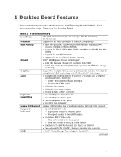
...® Matrix Storage Technology Support for multiple PCI Express* graphics cards including linked cards using Nvidia* SLI* technology and ATI CrossFireX* technology • Independent multi-streaming 8-channel (7.1) audio and 2-channel audio subsystem, featuring: ― Intel® High Definition Audio interface ― RealTek* ALC889 codec • HD Audio Link header • HD Audio front panel header • Onboard 3-pin S/PDIF connector • Two PCI Express 2.0 x16 ports • One PCI Express 2.0 x4 port • Two PCI Express 1.1 x1 ports • One PCI* bus connector Legacy...
...® Matrix Storage Technology Support for multiple PCI Express* graphics cards including linked cards using Nvidia* SLI* technology and ATI CrossFireX* technology • Independent multi-streaming 8-channel (7.1) audio and 2-channel audio subsystem, featuring: ― Intel® High Definition Audio interface ― RealTek* ALC889 codec • HD Audio Link header • HD Audio front panel header • Onboard 3-pin S/PDIF connector • Two PCI Express 2.0 x16 ports • One PCI Express 2.0 x4 port • Two PCI Express 1.1 x1 ports • One PCI* bus connector Legacy...
Product Guide
Page 10
... for extensible firmware interface • 16 Mb symmetrical flash memory device • Support for SMBIOS • Intel® Rapid BIOS Boot • Intel® Express BIOS Update Power Management • Support for Advanced Configuration and Power Interface (ACPI) • Suspend to RAM (STR) • Wake on USB, PCI, PCI Express, LAN, CIR, and front panel • ENERGY STAR* capable Hardware Management Hardware monitor with: • Four fan sensing inputs used to monitor fan activity • Intel® Precision Cooling Technology fan speed control • Voltage sensing...
... for extensible firmware interface • 16 Mb symmetrical flash memory device • Support for SMBIOS • Intel® Rapid BIOS Boot • Intel® Express BIOS Update Power Management • Support for Advanced Configuration and Power Interface (ACPI) • Suspend to RAM (STR) • Wake on USB, PCI, PCI Express, LAN, CIR, and front panel • ENERGY STAR* capable Hardware Management Hardware monitor with: • Four fan sensing inputs used to monitor fan activity • Intel® Precision Cooling Technology fan speed control • Voltage sensing...

Product Guide
Page 15
...; The back panel audio connectors, Figure 28 on page 52 15 Desktop Board Features Intel® X58 Express Chipset The Intel X58 Express Chipset consists of the following link or pages for more information about: • Audio drivers and utilities http://support.intel.com/support/motherboards/desktop/ • The location of 95 dB • Independent multi-streaming 8-channel (7.1) audio (using the back panel audio connectors) and 2-channel audio (using the Intel High Definition Audio front panel header) Related Links: Go to the processor and the PCI Express bus.
...; The back panel audio connectors, Figure 28 on page 52 15 Desktop Board Features Intel® X58 Express Chipset The Intel X58 Express Chipset consists of the following link or pages for more information about: • Audio drivers and utilities http://support.intel.com/support/motherboards/desktop/ • The location of 95 dB • Independent multi-streaming 8-channel (7.1) audio (using the back panel audio connectors) and 2-channel audio (using the Intel High Definition Audio front panel header) Related Links: Go to the processor and the PCI Express bus.

Product Guide
Page 16
... Mb/s) Ethernet LAN controller • RJ-45 LAN connector with integrated status LEDs • The subsystem features: • CSMA/CD protocol engine • LAN connect interface between ICH10R and the LAN controller • PCI bus power management Related Links: Go to the following link for information about LAN software and drivers: http://support.intel.com/support/motherboards/desktop Two LEDs are built into the RJ-45 LAN connector located on the back panel (see Figure...
... Mb/s) Ethernet LAN controller • RJ-45 LAN connector with integrated status LEDs • The subsystem features: • CSMA/CD protocol engine • LAN connect interface between ICH10R and the LAN controller • PCI bus power management Related Links: Go to the following link for information about LAN software and drivers: http://support.intel.com/support/motherboards/desktop Two LEDs are built into the RJ-45 LAN connector located on the back panel (see Figure...

Product Guide
Page 18
... Board DX58SO Product Guide The six onboard Serial ATA channels provided by ICH10R support the following expansion capability: • Two PCI Express 2.0 x16 ports • One PCI Express 2.0 x4 port • Two PCI Express 1.1 x1 ports • One PCI bus connector BIOS The BIOS provides the Power-On Self-Test (POST), the BIOS Setup program, and the PCI/PCI Express and IDE auto-configuration utilities. Serial ATA and IDE Auto Configuration If you install a Serial ATA or IDE device (such as a hard drive) in your computer. Legacy I/O Intel Desktop Board DX58SO includes an I/O controller...
... Board DX58SO Product Guide The six onboard Serial ATA channels provided by ICH10R support the following expansion capability: • Two PCI Express 2.0 x16 ports • One PCI Express 2.0 x4 port • Two PCI Express 1.1 x1 ports • One PCI bus connector BIOS The BIOS provides the Power-On Self-Test (POST), the BIOS Setup program, and the PCI/PCI Express and IDE auto-configuration utilities. Serial ATA and IDE Auto Configuration If you install a Serial ATA or IDE device (such as a hard drive) in your computer. Legacy I/O Intel Desktop Board DX58SO includes an I/O controller...

Product Guide
Page 19
... be set , you install a PCI/PCI Express add-in card in your computer, the PCI/PCI Express auto-configuration utility in the BIOS automatically detects and configures the resources (IRQs, DMA channels, and I/O space) for that add-in the processor • Thermally monitored closed-loop fan control, for a password. You do not need to run the BIOS Setup program after you can boot the computer. Related Links: For instructions on resetting the password, go to Clearing Passwords on...
... be set , you install a PCI/PCI Express add-in card in your computer, the PCI/PCI Express auto-configuration utility in the BIOS automatically detects and configures the resources (IRQs, DMA channels, and I/O space) for that add-in the processor • Thermally monitored closed-loop fan control, for a password. You do not need to run the BIOS Setup program after you can boot the computer. Related Links: For instructions on resetting the password, go to Clearing Passwords on...

Product Guide
Page 20
... BIOS Setup program's Boot menu. 20 The security feature uses a mechanical switch on the chassis that can turn off the computer power through the Advanced Configuration and Power Interface (ACPI) and the following hardware support: • Power connectors • Fan headers • LAN wake capabilities • Instantly Available PC technology (Suspend to the power state it was interrupted (either on the internal system temperature. See Figure 27 for the location of a computer. Intel Desktop Board DX58SO Product Guide Intel...
... BIOS Setup program's Boot menu. 20 The security feature uses a mechanical switch on the chassis that can turn off the computer power through the Advanced Configuration and Power Interface (ACPI) and the following hardware support: • Power connectors • Fan headers • LAN wake capabilities • Instantly Available PC technology (Suspend to the power state it was interrupted (either on the internal system temperature. See Figure 27 for the location of a computer. Intel Desktop Board DX58SO Product Guide Intel...

Product Guide
Page 21
...-toRAM) sleep state. Power supplies used with this Desktop Board must be off as needed. • All fan headers have a +12 V DC connection. Instantly Available PC technology enables the board to its last known awake state. 21 When signaled by the LED turning amber. Failure to provide adequate standby current when using this feature can adjust the fan speed or switch the fan on when the computer is wired to support the...
...-toRAM) sleep state. Power supplies used with this Desktop Board must be off as needed. • All fan headers have a +12 V DC connection. Instantly Available PC technology enables the board to its last known awake state. 21 When signaled by the LED turning amber. Failure to provide adequate standby current when using this feature can adjust the fan speed or switch the fan on when the computer is wired to support the...
Product Guide
Page 27
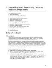
... you how to: • Install the I/O shield • Install and remove the Desktop Board • Install and remove a processor • Install the ICH heat sink decorative cover • Install the IOH heat sink fan • Install and remove memory • Install and remove a PCI Express x16 card • Connect the IDE and Serial ATA cables • Connect to the internal headers and connectors • Connect to the audio system • Connect chassis fan and power supply cables • Set the BIOS configuration jumper • Clear passwords • Replace the battery Before You Begin...
... you how to: • Install the I/O shield • Install and remove the Desktop Board • Install and remove a processor • Install the ICH heat sink decorative cover • Install the IOH heat sink fan • Install and remove memory • Install and remove a PCI Express x16 card • Connect the IDE and Serial ATA cables • Connect to the internal headers and connectors • Connect to the audio system • Connect chassis fan and power supply cables • Set the BIOS configuration jumper • Clear passwords • Replace the battery Before You Begin...
Product Guide
Page 53
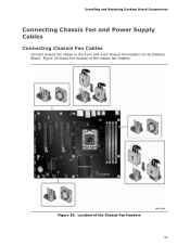
Figure 29 shows the location of the Chassis Fan Headers 53 Location of the chassis fan headers. Installing and Replacing Desktop Board Components Connecting Chassis Fan and Power Supply Cables Connecting Chassis Fan Cables Connect chassis fan cables to the 3-pin and 4-pin chassis fan headers on the Desktop Board. Figure 29.
Figure 29 shows the location of the Chassis Fan Headers 53 Location of the chassis fan headers. Installing and Replacing Desktop Board Components Connecting Chassis Fan and Power Supply Cables Connecting Chassis Fan Cables Connect chassis fan cables to the 3-pin and 4-pin chassis fan headers on the Desktop Board. Figure 29.

Product Guide
Page 56
... outlet or power adapter). 3. Jumper Settings for the BIOS Setup Program Modes Jumper Setting Mode Normal (default) (1-2) Description The BIOS uses the current configuration and passwords for booting. Place the jumper on the computer, and allow it to save the current values and exit Setup. 10. Press to boot. 7. Replace the cover, plug in the computer and the configuration jumper block is installed in the computer, turn on pins 2-3 as shown below. 6. Intel Desktop Board DX58SO Product Guide Table...
... outlet or power adapter). 3. Jumper Settings for the BIOS Setup Program Modes Jumper Setting Mode Normal (default) (1-2) Description The BIOS uses the current configuration and passwords for booting. Place the jumper on the computer, and allow it to save the current values and exit Setup. 10. Press to boot. 7. Replace the cover, plug in the computer and the configuration jumper block is installed in the computer, turn on pins 2-3 as shown below. 6. Intel Desktop Board DX58SO Product Guide Table...
Product Guide
Page 63
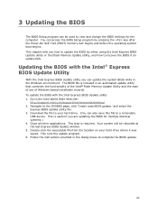
...: http://support.intel.com/support/motherboards/desktop/ 2. Download the file to your hard drive where it was saved. This is required. You can access the BIOS Setup program by either using the Intel Express BIOS Update utility or the Iflash Memory Update utility, and how to complete the BIOS update. 63 Your system will be used to a removable USB device. Close all other applications. This chapter tells you how to update the BIOS by pressing the key after the Power-On...
...: http://support.intel.com/support/motherboards/desktop/ 2. Download the file to your hard drive where it was saved. This is required. You can access the BIOS Setup program by either using the Intel Express BIOS Update utility or the Iflash Memory Update utility, and how to complete the BIOS update. 63 Your system will be used to a removable USB device. Close all other applications. This chapter tells you how to update the BIOS by pressing the key after the Power-On...

Product Guide
Page 64
... Toolkit Configuration File (optional) • Intel Flash Memory Update Utility You can obtain either of uncompressing and writing the ISO image file to update the BIOS. The Iflash BIOS update file is a standardized image of a bootable CD-ROM that contains the files you need to a new version of the BIOS by navigating to the Intel Desktop Board DX58SO page on the Intel World Wide Web site at: http://support.intel.com/support/motherboards/desktop Navigate to update the BIOS using...
... Toolkit Configuration File (optional) • Intel Flash Memory Update Utility You can obtain either of uncompressing and writing the ISO image file to update the BIOS. The Iflash BIOS update file is a standardized image of a bootable CD-ROM that contains the files you need to a new version of the BIOS by navigating to the Intel Desktop Board DX58SO page on the Intel World Wide Web site at: http://support.intel.com/support/motherboards/desktop Navigate to update the BIOS using...

Product Guide
Page 68
... on supported USB floppy disk drives. Refer to install a third-party SCSI or RAID driver. The Intel Matrix Storage Console software can be used to a RAID setup. 68 Intel Desktop Board DX58SO Product Guide Loading the Intel Matrix Storage Technology RAID Drivers and Software 1. Once additional SATA drives have been added to the system, open the Intel Matrix Storage Technology Console Software and follow the directions to update to manage the RAID configuration. Install the Intel® ICH10R SATA RAID Controller driver. 3. Setting Up a "RAID Ready" System The Intel Matrix Storage...
... on supported USB floppy disk drives. Refer to install a third-party SCSI or RAID driver. The Intel Matrix Storage Console software can be used to a RAID setup. 68 Intel Desktop Board DX58SO Product Guide Loading the Intel Matrix Storage Technology RAID Drivers and Software 1. Once additional SATA drives have been added to the system, open the Intel Matrix Storage Technology Console Software and follow the directions to update to manage the RAID configuration. Install the Intel® ICH10R SATA RAID Controller driver. 3. Setting Up a "RAID Ready" System The Intel Matrix Storage...
Product Guide
Page 69
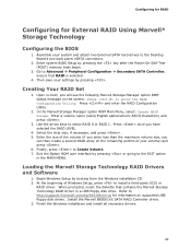
... contains the Marvell Storage Technology RAID Driver in the MAIN MENU. Creating Your RAID Set 1. Refer to Create Volume. 7. Loading the Marvell Storage Technology RAID Drivers and Software 1. Begin Windows Setup by pressing the key after the Power-On-Self-Test (POST) memory tests begin. 3. Enter system BIOS Setup by booting from the Windows installation CD. 2. Enter a volume name (using English alphanumeric ASCII characters) and press . 3. Finish the Windows installation and install all necessary drivers. 69 Go to enter the RAID Configuration Utility. When prompted, insert...
... contains the Marvell Storage Technology RAID Driver in the MAIN MENU. Creating Your RAID Set 1. Refer to Create Volume. 7. Loading the Marvell Storage Technology RAID Drivers and Software 1. Begin Windows Setup by pressing the key after the Power-On-Self-Test (POST) memory tests begin. 3. Enter system BIOS Setup by booting from the Windows installation CD. 2. Enter a volume name (using English alphanumeric ASCII characters) and press . 3. Finish the Windows installation and install all necessary drivers. 69 Go to enter the RAID Configuration Utility. When prompted, insert...


