
English Manual
Page 1
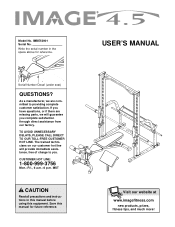
... complete customer satisfaction. If you . MST CAUTION Read all precautions and instructions in the space above for future reference. Write the serial number in this manual before using this manual for reference. TO AVOID UNNECESSARY DELAYS, PLEASE CALL DIRECT TO OUR TOLL-FREE CUSTOMER HOT LINE. The trained technicians on our customer hot line will guarantee you complete satisfaction through...
... complete customer satisfaction. If you . MST CAUTION Read all precautions and instructions in the space above for future reference. Write the serial number in this manual before using this manual for reference. TO AVOID UNNECESSARY DELAYS, PLEASE CALL DIRECT TO OUR TOLL-FREE CUSTOMER HOT LINE. The trained technicians on our customer hot line will guarantee you complete satisfaction through...
English Manual
Page 2
IMAGE is attached in the center of ICON Health & Fitness, Inc. 2 Table of Contents Important Precautions 3 Before You Begin 4 Part Identification Chart 5 Assembly 6 Adjusting the Weight Bench 13 Ordering Replacement Parts Back Cover Limited Warranty Back Cover Note: A Part List/Exploded Drawing is a registered trademark of this manual. Remove the Part List/Exploded Drawing before beginning assembly.
IMAGE is attached in the center of ICON Health & Fitness, Inc. 2 Table of Contents Important Precautions 3 Before You Begin 4 Part Identification Chart 5 Assembly 6 Adjusting the Weight Bench 13 Ordering Replacement Parts Back Cover Limited Warranty Back Cover Note: A Part List/Exploded Drawing is a registered trademark of this manual. Remove the Part List/Exploded Drawing before beginning assembly.
English Manual
Page 3
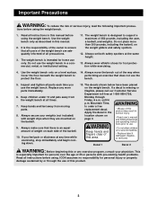
... a free replacement decal. Decal 1 Decal 2 WARNING: Before beginning this product. 3 Do not use of this manual. 2. Always wear athletic shoes for home use the protect the floor. Inspect and tighten all warnings and operating instructions prior to use the weight bench. WARNING • Misuse of this or any worn parts immediately. 6. This is the responsibility of the owner to performing an exercise that all users...
... a free replacement decal. Decal 1 Decal 2 WARNING: Before beginning this product. 3 Do not use of this manual. 2. Always wear athletic shoes for home use the protect the floor. Inspect and tighten all warnings and operating instructions prior to use the weight bench. WARNING • Misuse of this or any worn parts immediately. 6. This is the responsibility of the owner to performing an exercise that all users...
English Manual
Page 4
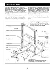
... Spotter Backrest Seat Leg Lever Note: The terms "right side" and "left on a decal attached to help us assist you for selecting the versatile IMAGE® 4.5 weight bench. If you want. toll-free at 1-800-999-3756, Monday through Friday, 6 a.m. The model number is designed to the weight bench (see the front cover of this manual. Left Side Upright Dumbbell Storage Rack Weight Storage Tube Backrest Adjustment Bracket...
... Spotter Backrest Seat Leg Lever Note: The terms "right side" and "left on a decal attached to help us assist you for selecting the versatile IMAGE® 4.5 weight bench. If you want. toll-free at 1-800-999-3756, Monday through Friday, 6 a.m. The model number is designed to the weight bench (see the front cover of this manual. Left Side Upright Dumbbell Storage Rack Weight Storage Tube Backrest Adjustment Bracket...
English Manual
Page 5
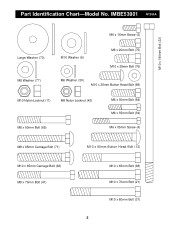
IMBE53901 R1200A M10 x 190mm Bolt (22) M6 x 16mm Screw (3) Large Washer (70) M8 Washer (77) M10 Washer (6) M8 x 20mm Bolt (75) M10 x 25mm Bolt (76) M6 Washer (30) M10 x 25mm Button Head Bolt (69) M10 Nylon Locknut (11) M8 Nylon Locknut (42) M8 x 60mm Bolt (65) M8 x 30mm Bolt (64) M6 x 35mm Bolt (34) M6 x 55mm Screw (4) M8 x 65mm Carriage Bolt (71) M10 x 60mm Button Head Bolt (12) M10 x 65mm Carriage Bolt (66) M8 x 70mm Bolt (41) M10 x 65mm Bolt (68) M10 x 70mm Bolt (21) M10 x 80mm Bolt (31) 5 Part Identification Chart-Model No.
IMBE53901 R1200A M10 x 190mm Bolt (22) M6 x 16mm Screw (3) Large Washer (70) M8 Washer (77) M10 Washer (6) M8 x 20mm Bolt (75) M10 x 25mm Bolt (76) M6 Washer (30) M10 x 25mm Button Head Bolt (69) M10 Nylon Locknut (11) M8 Nylon Locknut (42) M8 x 60mm Bolt (65) M8 x 30mm Bolt (64) M6 x 35mm Bolt (34) M6 x 55mm Screw (4) M8 x 65mm Carriage Bolt (71) M10 x 60mm Button Head Bolt (12) M10 x 65mm Carriage Bolt (66) M8 x 70mm Bolt (41) M10 x 65mm Bolt (68) M10 x 70mm Bolt (21) M10 x 80mm Bolt (31) 5 Part Identification Chart-Model No.
English Manual
Page 6
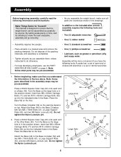
... M8 x 70mm Bolts (41), a Large Support 66 Plate (50), and two M8 Nylon Locknuts (42). Turn the Base so the large hole is completed. • Tighten all parts as you assemble the weight bench, make sure that the weight bench can be pre-assembled. • As you assemble them, unless instructed to do otherwise. • For help identifying small parts, use the PART IDENTIFICATION CHART on the...
... M8 x 70mm Bolts (41), a Large Support 66 Plate (50), and two M8 Nylon Locknuts (42). Turn the Base so the large hole is completed. • Tighten all parts as you assemble the weight bench, make sure that the weight bench can be pre-assembled. • As you assemble them, unless instructed to do otherwise. • For help identifying small parts, use the PART IDENTIFICATION CHART on the...

English Manual
Page 7
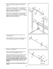
... (39) into the end of the 3 Uprights (43). Press a 25mm Round Inner Cap (39) into the end of 4 a Weight Storage Tube (55). 44 While a second person holds the Middle Crossbar (47) in the left Brace (44), and the bracket on one of 5 the other Upright (43) and Brace (44). 43 11... person continues to the Upright with the other Weight Storage Tube (55). 3. Attach the Brace with two M10 Nylon Locknuts (11). Thread an M10 Nylon Locknut (11) onto each Bolt. Do not tighten the Nylon Locknuts yet. 21 39 39 21 55 21 47 44 11 7 Repeat this step on the Middle Crossbar....
... (39) into the end of the 3 Uprights (43). Press a 25mm Round Inner Cap (39) into the end of 4 a Weight Storage Tube (55). 44 While a second person holds the Middle Crossbar (47) in the left Brace (44), and the bracket on one of 5 the other Upright (43) and Brace (44). 43 11... person continues to the Upright with the other Weight Storage Tube (55). 3. Attach the Brace with two M10 Nylon Locknuts (11). Thread an M10 Nylon Locknut (11) onto each Bolt. Do not tighten the Nylon Locknuts yet. 21 39 39 21 55 21 47 44 11 7 Repeat this step on the Middle Crossbar....
English Manual
Page 8
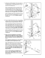
... 11 48 11 11 Pull-up bar faces away from the rack, as shown in the Locking Bar. 73 62 8. Secure the Weight Glider to the right Upright (43) with a hand-tightened M8 x 20mm Bolt (75). 63 Look at the position of the round tube. 8 Press a 38mm Bushing (58) into each...Attach the Top Crossbar (48) to make sure that the pull-up Bar 11 43 43 51 21 21 7. Do not tighten the Nylon Locknuts yet. Press a 25mm Bushing (73) into each end of the Barbell (63). The Left Weight Glider must be turned as shown. Repeat this step with two M10 x 70mm Bolts (21), a Small Support...
... 11 48 11 11 Pull-up bar faces away from the rack, as shown in the Locking Bar. 73 62 8. Secure the Weight Glider to the right Upright (43) with a hand-tightened M8 x 20mm Bolt (75). 63 Look at the position of the round tube. 8 Press a 38mm Bushing (58) into each...Attach the Top Crossbar (48) to make sure that the pull-up Bar 11 43 43 51 21 21 7. Do not tighten the Nylon Locknuts yet. Press a 25mm Bushing (73) into each end of the Barbell (63). The Left Weight Glider must be turned as shown. Repeat this step with two M10 x 70mm Bolts (21), a Small Support...
English Manual
Page 9
..., tighten the M8 x 20mm Screws used in the direction shown. Note: The handle must fit into the indentation in the 50mm Bushing in case you need to the Barbell with the weight rack, you insert it. Pull the remaining length of a Weight Adapter (61). Insert a Weight Guide (53) into the end of the Barbell (63) in steps 9 and 10. Note: Tilt the Weight Guide...
..., tighten the M8 x 20mm Screws used in the direction shown. Note: The handle must fit into the indentation in the 50mm Bushing in case you need to the Barbell with the weight rack, you insert it. Pull the remaining length of a Weight Adapter (61). Insert a Weight Guide (53) into the end of the Barbell (63) in steps 9 and 10. Note: Tilt the Weight Guide...
English Manual
Page 10
... Weight Guide (53) to the bracket on the Upright (43) with two M10 x 70mm Bolts (21), two M10 Washers (6), and two M10 Nylon Locknuts (11). Press a 50mm x 70mm Outer Cap (10) onto each end of the Stabilizer (13). Attach the Bench Base Joint Plate (19) to 12. 64 77 53 43 13. Tighten all the Nylon Locknuts used in steps...
... Weight Guide (53) to the bracket on the Upright (43) with two M10 x 70mm Bolts (21), two M10 Washers (6), and two M10 Nylon Locknuts (11). Press a 50mm x 70mm Outer Cap (10) onto each end of the Stabilizer (13). Attach the Bench Base Joint Plate (19) to 12. 64 77 53 43 13. Tighten all the Nylon Locknuts used in steps...
English Manual
Page 11
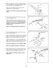
... turned as shown. Press two 25mm x 40mm Inner Caps (28) into the open end of the Bench Frame. Press the 20mm x 50mm Inner Cap (33) into each Backrest Tube (27). Note: Do not over tighten the Nylon Locknut; Lubricate an M10 x 190mm Bolt (22). Make sure that the Seat Adjustment Bracket (36) fits over tighten the Nylon Locknut; Lubricate an M8 x 70mm Bolt (41). Attach...
... turned as shown. Press two 25mm x 40mm Inner Caps (28) into the open end of the Bench Frame. Press the 20mm x 50mm Inner Cap (33) into each Backrest Tube (27). Note: Do not over tighten the Nylon Locknut; Lubricate an M10 x 190mm Bolt (22). Make sure that the Seat Adjustment Bracket (36) fits over tighten the Nylon Locknut; Lubricate an M8 x 70mm Bolt (41). Attach...
English Manual
Page 12
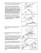
...Adjustable Bench Leg (2). 20 14 Bracket 23 30 3 34 21 40 2 37 1 22. Attach the Adjustable Bench Leg (2) to the bracket on the 26 Adjustable Bench Leg (2). Note: Do not over tighten the M10 Nylon Locknut; Slide a Foam Pad (25) onto each side of the Leg Lever (17). Insert a 45mm Square Inner Cap (40) into the weight...ends of the Seat to the Bench Leg (1) with two M6 x 16mm Screws (3). Press a 25mm Angled Outer Cap (38) onto the other end of the Seat (14) to the Adjustable Bench Leg (2) with an M6 x 35mm Bolt (34) and an M6 Washer (30). 21. Attach the wide ...
...Adjustable Bench Leg (2). 20 14 Bracket 23 30 3 34 21 40 2 37 1 22. Attach the Adjustable Bench Leg (2) to the bracket on the 26 Adjustable Bench Leg (2). Note: Do not over tighten the M10 Nylon Locknut; Slide a Foam Pad (25) onto each side of the Leg Lever (17). Insert a 45mm Square Inner Cap (40) into the weight...ends of the Seat to the Bench Leg (1) with two M6 x 16mm Screws (3). Press a 25mm Angled Outer Cap (38) onto the other end of the Seat (14) to the Adjustable Bench Leg (2) with an M6 x 35mm Bolt (34) and an M6 Washer (30). 21. Attach the wide ...
English Manual
Page 13
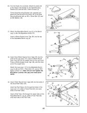
... in ADJUSTING THE WEIGHT BENCH starting an exercise, position the Barbell (63) and 43 the Safety Spotters (56, 57) in the correct position for important information about how to get the greatest benefit from your exercise program. Turn the Locking Bar until it will be cleaned with 24 two M6 x 16mm Screws (3). 8 25. Inspect and tighten all parts are properly tightened before you use solvents...
... in ADJUSTING THE WEIGHT BENCH starting an exercise, position the Barbell (63) and 43 the Safety Spotters (56, 57) in the correct position for important information about how to get the greatest benefit from your exercise program. Turn the Locking Bar until it will be cleaned with 24 two M6 x 16mm Screws (3). 8 25. Inspect and tighten all parts are properly tightened before you use solvents...
English Manual
Page 14
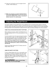
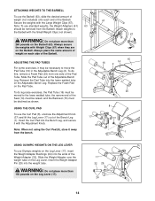
... weight tube on the Adjustable Bench Leg. Reinsert the Pad Tube into the ends of the Weight Adapter (32). Insert the Weight Adapter Pin (29) into the Bench Leg, and secure it may be moved to move the Pad Tube (16) in the Adjustable Bench Leg (2). ADJUSTING THE PAD TUBES For some exercises, it with Weight Clips (67) when they are on the Barbell (63). ATTACHING WEIGHTS TO THE BARBELL To use...
... weight tube on the Adjustable Bench Leg. Reinsert the Pad Tube into the ends of the Weight Adapter (32). Insert the Weight Adapter Pin (29) into the Bench Leg, and secure it may be moved to move the Pad Tube (16) in the Adjustable Bench Leg (2). ADJUSTING THE PAD TUBES For some exercises, it with Weight Clips (67) when they are on the Barbell (63). ATTACHING WEIGHTS TO THE BARBELL To use...
English Manual
Page 15
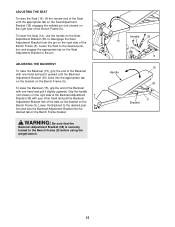
... lower the Seat (14), use the handle on the Seat Adjustment Bracket (36) to the pin. To lower the Backrest (15), grip the end of the Backrest with your other hand and pull the Backrest Adjustment Bracket free of the Backrest Adjustment Bracket (35) with one hand and pull it slightly upwards. Lower the Backrest to the Bench Frame (5) before using the weight bench. 14...
... lower the Seat (14), use the handle on the Seat Adjustment Bracket (36) to the pin. To lower the Backrest (15), grip the end of the Backrest with your other hand and pull the Backrest Adjustment Bracket free of the Backrest Adjustment Bracket (35) with one hand and pull it slightly upwards. Lower the Backrest to the Bench Frame (5) before using the weight bench. 14...
English Manual
Page 16
... MODEL NUMBER of the product (IMBE53901) • The NAME of the product (IMAGE® 4.5 weight bench) • The SERIAL NUMBER of the product (see the front cover of this manual) • The KEY NUMBER and DESCRIPTION of the desired part(s) (see the PART LIST and the EXPLODED DRAWING at one of its authorized service centers. Some states do not allow limitations on how long an implied warranty...
... MODEL NUMBER of the product (IMBE53901) • The NAME of the product (IMAGE® 4.5 weight bench) • The SERIAL NUMBER of the product (see the front cover of this manual) • The KEY NUMBER and DESCRIPTION of the desired part(s) (see the PART LIST and the EXPLODED DRAWING at one of its authorized service centers. Some states do not allow limitations on how long an implied warranty...
English Manual
Page 17
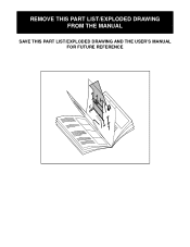
REMOVE THIS PART LIST/EXPLODED DRAWING FROM THE MANUAL SAVE THIS PART LIST/EXPLODED DRAWING AND THE USER'S MANUAL FOR FUTURE REFERENCE 81
REMOVE THIS PART LIST/EXPLODED DRAWING FROM THE MANUAL SAVE THIS PART LIST/EXPLODED DRAWING AND THE USER'S MANUAL FOR FUTURE REFERENCE 81
English Manual
Page 18
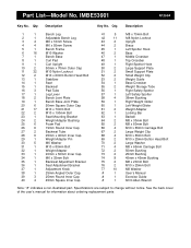
... 71 4 M8 x 65mm Carriage Bolt 72 2 50mm Bushing 73 2 25mm Bushing 74 8 45mm x 45mm Bushing 75 2 M8 x 20mm Bolt 76 2 M10 x 25mm Bolt 77 10 M8 Washer # 1 User's Manual # 1 Exercise Guide # 1 6mm Allen Wrench Note: "#" indicates a non-illustrated part. Qty. Specifications are subject to change without notice. IMBE53901 R1200A Key No. See the back cover of the user's manual for information about ordering replacement parts. Part List-Model No. Qty.
... 71 4 M8 x 65mm Carriage Bolt 72 2 50mm Bushing 73 2 25mm Bushing 74 8 45mm x 45mm Bushing 75 2 M8 x 20mm Bolt 76 2 M10 x 25mm Bolt 77 10 M8 Washer # 1 User's Manual # 1 Exercise Guide # 1 6mm Allen Wrench Note: "#" indicates a non-illustrated part. Qty. Specifications are subject to change without notice. IMBE53901 R1200A Key No. See the back cover of the user's manual for information about ordering replacement parts. Part List-Model No. Qty.
English Manual
Page 19
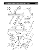
... 66 51 67 21 52 43 11 44 6 6 68 55 21 42 77 39 11 20 46 50 41 71 77 65 R1200A Exploded Drawing-Model No. IMBE53901
... 66 51 67 21 52 43 11 44 6 6 68 55 21 42 77 39 11 20 46 50 41 71 77 65 R1200A Exploded Drawing-Model No. IMBE53901


