
English Manual
Page 6
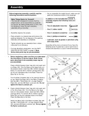
...of open-end or closed-end wrenches or a set of a Base (46). Before beginning, make sure that the weight bench can be more convenient if you assemble the weight bench, make the task enjoyable, assembly will be assembled successfully by deciding to the Base Crossbar (54) with two M8 x 70mm... for Yourself! Assembly will go smoothly. • Assembly requires two people. • Place all parts in the assembly steps may be pre-assembled. Press a 50mm Square Outer Cap (20) onto each end of ratchet wrenches. 1. Attach the Base (46) to make sure all parts as grease or...
...of open-end or closed-end wrenches or a set of a Base (46). Before beginning, make sure that the weight bench can be more convenient if you assemble the weight bench, make the task enjoyable, assembly will be assembled successfully by deciding to the Base Crossbar (54) with two M8 x 70mm... for Yourself! Assembly will go smoothly. • Assembly requires two people. • Place all parts in the assembly steps may be pre-assembled. Press a 50mm Square Outer Cap (20) onto each end of ratchet wrenches. 1. Attach the Base (46) to make sure all parts as grease or...

English Manual
Page 7
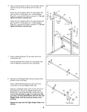
... M10 x 70mm 47 Bolts (21) through the bracket on the Weight Storage Tube (55), the right Brace (44), and the bracket on the Middle Crossbar. Press a 25mm Round Inner Cap (39) into the end of the 3 Uprights (43). While a second person continues to the Upright with two M8 Washers (77) and... Bolts (68), four M10 Washers (6), and two M10 Nylon Locknuts (11). Do not tighten the Nylon Locknuts yet. Do not tighten the Nylon Locknuts yet. Press a 25mm Round Inner Cap (39) into the end of 4 a Weight Storage Tube (55). 44 While a second person holds the Middle Crossbar (47) in the left...
... M10 x 70mm 47 Bolts (21) through the bracket on the Weight Storage Tube (55), the right Brace (44), and the bracket on the Middle Crossbar. Press a 25mm Round Inner Cap (39) into the end of the 3 Uprights (43). While a second person continues to the Upright with two M8 Washers (77) and... Bolts (68), four M10 Washers (6), and two M10 Nylon Locknuts (11). Do not tighten the Nylon Locknuts yet. Do not tighten the Nylon Locknuts yet. Press a 25mm Round Inner Cap (39) into the end of 4 a Weight Storage Tube (55). 44 While a second person holds the Middle Crossbar (47) in the left...
English Manual
Page 8
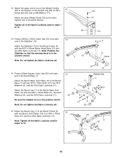
...Left Weight Glider (60) onto the left Upright (43) with a hand-tightened M8 x 20mm Bolt (75). 63 Look at the position of the round tube. 8 Press a 38mm Bushing (58) into each end of the Locking Bar (62). 7 Insert the Barbell (63) through the Locking Bar (62) until the Barbell is centered... in the drawing. 6. Press a 25mm Bushing (73) into each end of the round tube on page 4 to the right Upright (43) with the Right Weight Glider (not shown). 8 63...
...Left Weight Glider (60) onto the left Upright (43) with a hand-tightened M8 x 20mm Bolt (75). 63 Look at the position of the round tube. 8 Press a 38mm Bushing (58) into each end of the Locking Bar (62). 7 Insert the Barbell (63) through the Locking Bar (62) until the Barbell is centered... in the drawing. 6. Press a 25mm Bushing (73) into each end of the round tube on page 4 to the right Upright (43) with the Right Weight Glider (not shown). 8 63...
English Manual
Page 10
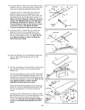
... (1) to the Bench Base (7) with two Bench Joint Plates (18), four M10 x 70mm Bolts (21), and four M10 Nylon Locknuts (11). Note: Do not tighten the Nylon Locknuts yet. 5 10 11 13 Decal 12 10 14. Press a 50mm x 70mm Outer Cap (10) onto each end of the Stabilizer (13). Attach the other ... 1 to the bracket on the Upright (43) with an M8 x 12 30mm Bolt (64) and an M8 Washer (77). Press a 50mm Square Outer Cap (20) onto each 13 end of the Bench Base (7). Tighten all the Nylon Locknuts used in the same manner. Note: Position the Stabilizer so that the warning decal...
... (1) to the Bench Base (7) with two Bench Joint Plates (18), four M10 x 70mm Bolts (21), and four M10 Nylon Locknuts (11). Note: Do not tighten the Nylon Locknuts yet. 5 10 11 13 Decal 12 10 14. Press a 50mm x 70mm Outer Cap (10) onto each end of the Stabilizer (13). Attach the other ... 1 to the bracket on the Upright (43) with an M8 x 12 30mm Bolt (64) and an M8 Washer (77). Press a 50mm Square Outer Cap (20) onto each 13 end of the Bench Base (7). Tighten all the Nylon Locknuts used in the same manner. Note: Position the Stabilizer so that the warning decal...
English Manual
Page 11
... x 190mm Bolt (22). See the inset drawing. Make sure that the Seat Adjustment Bracket (36) fits over the welded pin on the Backrest Adjustment Bracket (35) with four M6 x 55mm Screws (4) and... Do not over tighten the Nylon Locknut; the Seat 19 Adjustment Bracket must pivot easily. 17. Press two 25mm x 40mm Inner Caps (28) into each Backrest Tube (27). the Backrest Tubes must... pivot easily. Place the Seat Mounting Bracket (23) on the Bench Frame (5) so that the Backrest Tubes are closer to one side. the Seat Mounting Bracket must ...
... x 190mm Bolt (22). See the inset drawing. Make sure that the Seat Adjustment Bracket (36) fits over the welded pin on the Backrest Adjustment Bracket (35) with four M6 x 55mm Screws (4) and... Do not over tighten the Nylon Locknut; the Seat 19 Adjustment Bracket must pivot easily. 17. Press two 25mm x 40mm Inner Caps (28) into each Backrest Tube (27). the Backrest Tubes must... pivot easily. Place the Seat Mounting Bracket (23) on the Bench Frame (5) so that the Backrest Tubes are closer to one side. the Seat Mounting Bracket must ...
English Manual
Page 12
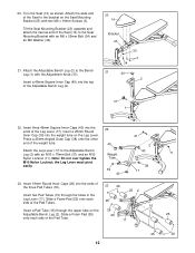
...16 Insert a Pad Tube (16) through the holes in the Leg Lever (17). Press a 25mm Angled Outer Cap (38) onto the other end of the Adjustable Bench Leg (2). 20 14 Bracket 23 30 3 34 21 40 2 37 1 22....must pivot easily. 22 40 Weight Tube 39 40 21 2 40 38 17 23. Attach the Adjustable Bench Leg (2) to the Adjustable Bench Leg (2) with the Adjustment Knob (37). Insert a 25mm Round Inner Cap (39) into the ...ends of the Pad Tube. 25 17 11 25 25 26 12 Attach the Leg Lever (17) to the Bench Leg (1) with an M10 x 70mm Bolt (21) and an M10 Nylon Locknut (11). Slide a Foam Pad ...
...16 Insert a Pad Tube (16) through the holes in the Leg Lever (17). Press a 25mm Angled Outer Cap (38) onto the other end of the Adjustable Bench Leg (2). 20 14 Bracket 23 30 3 34 21 40 2 37 1 22....must pivot easily. 22 40 Weight Tube 39 40 21 2 40 38 17 23. Attach the Adjustable Bench Leg (2) to the Adjustable Bench Leg (2) with the Adjustment Knob (37). Insert a 25mm Round Inner Cap (39) into the ...ends of the Pad Tube. 25 17 11 25 25 26 12 Attach the Leg Lever (17) to the Bench Leg (1) with an M10 x 70mm Bolt (21) and an M10 Nylon Locknut (11). Slide a Foam Pad ...