
English Manual
Page 1
Model No. USER'S MANUAL Visit our website at www.imagefitness.com new products, prizes, fitness tips, and much more! TO AVOID UNNECESSARY DELAYS, PLEASE CALL DIRECT TO OUR TOLL-FREE CUSTOMER HOT LINE. MST CAUTION Read all precautions and instructions ... a manufacturer, we are missing parts, we will provide immediate assistance, free of charge to providing complete customer satisfaction. IMBE53901 Serial No. Serial Number Decal (under seat) QUESTIONS? The trained technicians on our customer hot line will guarantee you . Save this equipment.
Model No. USER'S MANUAL Visit our website at www.imagefitness.com new products, prizes, fitness tips, and much more! TO AVOID UNNECESSARY DELAYS, PLEASE CALL DIRECT TO OUR TOLL-FREE CUSTOMER HOT LINE. MST CAUTION Read all precautions and instructions ... a manufacturer, we are missing parts, we will provide immediate assistance, free of charge to providing complete customer satisfaction. IMBE53901 Serial No. Serial Number Decal (under seat) QUESTIONS? The trained technicians on our customer hot line will guarantee you . Save this equipment.
English Manual
Page 4
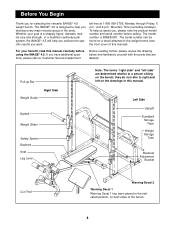
...please note the product model number and serial number before using the IMAGE® 4.5. Pull-up Bar Weight Guide Right Side Barbell Weight Glider Safety Spotter Backrest Seat Leg Lever Note: The terms "right side" and "left on the bench; The IMAGE® 4.5 is designed to a person sitting on the drawings... yourself with the parts that are determined relative to help you achieve the specific results you for selecting the versatile IMAGE® 4.5 weight bench. For your goal is IMBE53901. Before You Begin Thank you want. until 6 p.m. they do not refer to the weight...
...please note the product model number and serial number before using the IMAGE® 4.5. Pull-up Bar Weight Guide Right Side Barbell Weight Glider Safety Spotter Backrest Seat Leg Lever Note: The terms "right side" and "left on the bench; The IMAGE® 4.5 is designed to a person sitting on the drawings... yourself with the parts that are determined relative to help you achieve the specific results you for selecting the versatile IMAGE® 4.5 weight bench. For your goal is IMBE53901. Before You Begin Thank you want. until 6 p.m. they do not refer to the weight...
English Manual
Page 11
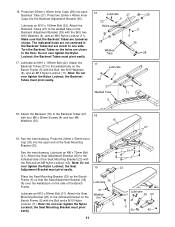
Make sure that the Seat Adjustment Bracket (36) fits over tighten the Nylon Locknut; Turn the Backrest Tubes so the holes are ...80mm Bolt (31). Lubricate an M10 x 190mm Bolt (22). Attach the Backrest Tubes (27) to the indicated side of the Seat Mounting Bracket (23) with the Bolt and a M10 Nylon Locknut (11). See the inset drawing. Lubricate an M8 x 70mm Bolt...Welded Tube 6 11 5 18. See the inset drawing. Place the Seat Mounting Bracket (23) on the Bench Frame (5) with the Bolt and an M8 Nylon Locknut (42). Attach the Seat Mounting Bracket (23) to one side. 16. Note: Do not ...
Make sure that the Seat Adjustment Bracket (36) fits over tighten the Nylon Locknut; Turn the Backrest Tubes so the holes are ...80mm Bolt (31). Lubricate an M10 x 190mm Bolt (22). Attach the Backrest Tubes (27) to the indicated side of the Seat Mounting Bracket (23) with the Bolt and a M10 Nylon Locknut (11). See the inset drawing. Lubricate an M8 x 70mm Bolt...Welded Tube 6 11 5 18. See the inset drawing. Place the Seat Mounting Bracket (23) on the Bench Frame (5) with the Bolt and an M8 Nylon Locknut (42). Attach the Seat Mounting Bracket (23) to one side. 16. Note: Do not ...
English Manual
Page 12
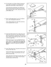
... the weight tube. Press a 25mm Angled Outer Cap (38) onto the other end of the Seat (14) to the bracket on the Seat Mounting Bracket (23) with the Adjustment Knob (37). Attach the Leg Lever (17) to the Bench Leg (1) with two M6 x 16mm Screws (3). Slide a Foam Pad (25) onto each side of... the Pad Tubes. 25 16 Insert a Pad Tube (16) through the holes in the Leg Lever (17). Turn the Seat (14) as shown. Attach the Adjustable Bench Leg (2) to the Adjustable Bench Leg (2) with an M6 x 35mm Bolt (34) and an M6 Washer (30). 21. Slide a Foam Pad (25) onto each side...
... the weight tube. Press a 25mm Angled Outer Cap (38) onto the other end of the Seat (14) to the bracket on the Seat Mounting Bracket (23) with the Adjustment Knob (37). Attach the Leg Lever (17) to the Bench Leg (1) with two M6 x 16mm Screws (3). Slide a Foam Pad (25) onto each side of... the Pad Tubes. 25 16 Insert a Pad Tube (16) through the holes in the Leg Lever (17). Turn the Seat (14) as shown. Attach the Adjustable Bench Leg (2) to the Adjustable Bench Leg (2) with an M6 x 35mm Bolt (34) and an M6 Washer (30). 21. Slide a Foam Pad (25) onto each side...
English Manual
Page 14
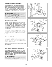
...Weight Adapters (61) 63 should be removed from one side of the Bench Leg 17 (1). Always place the same amount of the Seat (14) must be raised, and the Backrest (15) must be... necessary to the lower welded tube, the narrow end of weight on the Leg Lever. To do leg raise exercises, the Pad Tube (16) must be moved to move the Pad Tube (16) in the Adjustable Bench...on the Barbell (63). WARNING: Do not place more than 260 pounds on the Adjustable Bench Leg. Replace the Foam Pad on the Barbell. Slide the Pad Tube out of the ...
...Weight Adapters (61) 63 should be removed from one side of the Bench Leg 17 (1). Always place the same amount of the Seat (14) must be raised, and the Backrest (15) must be... necessary to the lower welded tube, the narrow end of weight on the Leg Lever. To do leg raise exercises, the Pad Tube (16) must be moved to move the Pad Tube (16) in the Adjustable Bench...on the Barbell (63). WARNING: Do not place more than 260 pounds on the Adjustable Bench Leg. Replace the Foam Pad on the Barbell. Slide the Pad Tube out of the ...
English Manual
Page 15
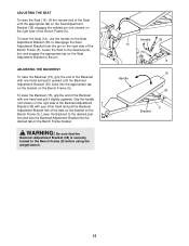
... Backrest Adjustment Bracket (35) with one hand and pull it slightly upwards. To lower the Seat (14), use the handle on the Seat Adjustment Bracket (36) to the Bench Frame (5) before using the weight bench. 14 Handle Handle 36 Pin 5 15 35 5 Bracket 15 WARNING: Be sure that the... Backrest Adjustment Bracket (35) is securely locked to disengage the Seat Adjustment Bracket from the pin on the right side of the Bench Frame (5). ADJUSTING THE SEAT To raise the Seat (14), lift the narrow end of the Seat until the Backrest Adjustment Bracket (35) locks into the desired ...
... Backrest Adjustment Bracket (35) with one hand and pull it slightly upwards. To lower the Seat (14), use the handle on the Seat Adjustment Bracket (36) to the Bench Frame (5) before using the weight bench. 14 Handle Handle 36 Pin 5 15 35 5 Bracket 15 WARNING: Be sure that the... Backrest Adjustment Bracket (35) is securely locked to disengage the Seat Adjustment Bracket from the pin on the right side of the Bench Frame (5). ADJUSTING THE SEAT To raise the Seat (14), lift the narrow end of the Seat until the Backrest Adjustment Bracket (35) locks into the desired ...
English Manual
Page 18
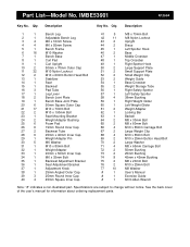
... Upright 10 2 50mm x 70mm Outer Cap 11 32 M10 Nylon Locknut 12 2 M10 x 60mm Button Head Bolt 13 1 Stabilizer 14 1 Seat 15 1 Backrest 16 3 Pad Tube 17 1 Leg Lever 18 2 Bench Joint Plate 19 1 Bench Base Joint Plate 20 6 50mm Square Outer Cap 21 17 M10 x 70mm Bolt 22 2 M10 x 190mm Bolt 23...
... Upright 10 2 50mm x 70mm Outer Cap 11 32 M10 Nylon Locknut 12 2 M10 x 60mm Button Head Bolt 13 1 Stabilizer 14 1 Seat 15 1 Backrest 16 3 Pad Tube 17 1 Leg Lever 18 2 Bench Joint Plate 19 1 Bench Base Joint Plate 20 6 50mm Square Outer Cap 21 17 M10 x 70mm Bolt 22 2 M10 x 190mm Bolt 23...