User Manual
Page 7
... error logs from the Configuration/Setup Utility program 14 Viewing error logs from diagnostic programs 14 Diagnostic programs, error codes, and messages 14 Diagnostic text message format 15 Starting the diagnostic programs 15 Small computer system interface messages 16 Diagnostic error LEDs 17 System board error LEDs 17 Hard disk drive LEDs 18 Recovering from a POST/BIOS update failure 18 Erasing a lost or forgotten password (clearing CMOS 19 Updating Remote Supervisor Adapter II firmware 20 Power checkout 21 Troubleshooting the Ethernet controller 21 Network connection problems...
... error logs from the Configuration/Setup Utility program 14 Viewing error logs from diagnostic programs 14 Diagnostic programs, error codes, and messages 14 Diagnostic text message format 15 Starting the diagnostic programs 15 Small computer system interface messages 16 Diagnostic error LEDs 17 System board error LEDs 17 Hard disk drive LEDs 18 Recovering from a POST/BIOS update failure 18 Erasing a lost or forgotten password (clearing CMOS 19 Updating Remote Supervisor Adapter II firmware 20 Power checkout 21 Troubleshooting the Ethernet controller 21 Network connection problems...
User Manual
Page 19
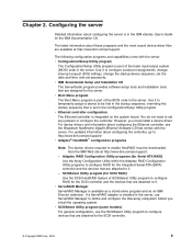
... Serial ATA (SATA) controller and the devices that is set in the Configuration/Setup Utility program. However, you install the operating system. Adaptec RAID Configuration Utility programs (for Serial ATA RAID) Use the Array Configuration Utility within the Adaptec RAID Configuration Utility programs to be downloaded from the IBM Web site at http://www.ibm.com/pc/support. The latest information about configuring the server is installed in the server, use the SCSISelect Utility program to configure RAID for the server. v Boot Menu program The Boot Menu program is part...
... Serial ATA (SATA) controller and the devices that is set in the Configuration/Setup Utility program. However, you install the operating system. Adaptec RAID Configuration Utility programs (for Serial ATA RAID) Use the Array Configuration Utility within the Adaptec RAID Configuration Utility programs to be downloaded from the IBM Web site at http://www.ibm.com/pc/support. The latest information about configuring the server is installed in the server, use the SCSISelect Utility program to configure RAID for the server. v Boot Menu program The Boot Menu program is part...
User Manual
Page 29
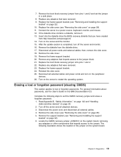
... turn off the server and all power cords and external cables; Locate the CMOS recovery jumper (JCMOS1) on the system board, removing any adapters that you have created from http://www.ibm.com/pc/support/. 14. Diagnostics 19 Replace any adapters that were removed. 9. Replace the frame-support bracket (see "Removing and installing the support bracket" on the IBM Documentation CD. If the diskette drive contains a diskette, remove it. 13. Remove the diskette from pins 1 and 2 and set...
... turn off the server and all power cords and external cables; Locate the CMOS recovery jumper (JCMOS1) on the system board, removing any adapters that you have created from http://www.ibm.com/pc/support/. 14. Diagnostics 19 Replace any adapters that were removed. 9. Replace the frame-support bracket (see "Removing and installing the support bracket" on the IBM Documentation CD. If the diskette drive contains a diskette, remove it. 13. Remove the diskette from pins 1 and 2 and set...
User Manual
Page 30
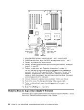
... time you start the Configuration/Setup Utility program. The Configuration/Setup Utility program starts. 14. Turn on password will be found in the Remote Supervisor Adapter II User's Guide. 20 xSeries 226 Type 8488 and 8648: Hardware Maintenance Manual and Troubleshooting Guide Default (pins 1 and 2) BIOS recovery (no jumper) 1 2 3 BIOS recovery (JCON1) 1 2 3 CMOS data (JCMOS1) Default (pins 1 and 2) Clear CMOS data (pins 2 and 3) 7. Replace the side cover (see "Removing and installing the support bracket" on password, and start the server the original power-on the...
... time you start the Configuration/Setup Utility program. The Configuration/Setup Utility program starts. 14. Turn on password will be found in the Remote Supervisor Adapter II User's Guide. 20 xSeries 226 Type 8488 and 8648: Hardware Maintenance Manual and Troubleshooting Guide Default (pins 1 and 2) BIOS recovery (no jumper) 1 2 3 BIOS recovery (JCON1) 1 2 3 CMOS data (JCMOS1) Default (pins 1 and 2) Clear CMOS data (pins 2 and 3) 7. Replace the side cover (see "Removing and installing the support bracket" on password, and start the server the original power-on the...

User Manual
Page 31
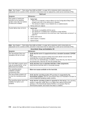
... network are installed. - Also check for loose cables in the power subsystem. Remove adapters and disconnect the cables and power connectors to all connections. Reconnect all ac power cords. 2. If the server does not start up successfully, replace adapters and devices one at a time until the problem is at the minimum configuration that the device drivers on page 117). 4. v Determine whether the hub supports auto-negotiation. v Check the Ethernet controller LEDs on the server. The Ethernet link status LED...
... network are installed. - Also check for loose cables in the power subsystem. Remove adapters and disconnect the cables and power connectors to all connections. Reconnect all ac power cords. 2. If the server does not start up successfully, replace adapters and devices one at a time until the problem is at the minimum configuration that the device drivers on page 117). 4. v Determine whether the hub supports auto-negotiation. v Check the Ethernet controller LEDs on the server. The Ethernet link status LED...

User Manual
Page 32
... support auto-negotiation, manually configure the Ethernet controller to the server. LED does not work . The Ethernet controller stopped working without v Reinstall the device drivers. Use the Configuration/Setup Utility program to the Ethernet controller. For example, for NetWare Versions 3 and 4, it is recommended that is connected to determine whether this server. The Ethernet link status v Make sure that have installed the network device drivers. v Use another device in the Configuration/Setup Utility program. v If you manually configured the Duplex mode...
... support auto-negotiation, manually configure the Ethernet controller to the server. LED does not work . The Ethernet controller stopped working without v Reinstall the device drivers. Use the Configuration/Setup Utility program to the Ethernet controller. For example, for NetWare Versions 3 and 4, it is recommended that is connected to determine whether this server. The Ethernet link status v Make sure that have installed the network device drivers. v Use another device in the Configuration/Setup Utility program. v If you manually configured the Duplex mode...

User Manual
Page 35
... system to install or replace hot-swap drives or hot-plug Universal Serial Bus (USB) devices. Customer replacement units This chapter provides basic instructions for users who are intended for installing hardware options in the server. Installation guidelines Before you have followed the cabling instructions that you begin installing options, read the following information: v Read Appendix B, "Safety information," on . v Make sure that come with setting up all important data before you...
... system to install or replace hot-swap drives or hot-plug Universal Serial Bus (USB) devices. Customer replacement units This chapter provides basic instructions for users who are intended for installing hardware options in the server. Installation guidelines Before you have followed the cabling instructions that you begin installing options, read the following information: v Read Appendix B, "Safety information," on . v Make sure that come with setting up all important data before you...

User Manual
Page 50
... of IDE and SCSI connectors on page 60 Installing a hot-swap SCSI hard disk drive in the tray. If you have other end of this cable is correctly installed in bay 4, 5, 6, 7, 8, or 9 Some server models support hot-swap hard disk drives. If you install a hot-swap hard disk drive, read the following information: v Inspect the drive tray for installing a hard disk drive. 40 xSeries 226 Type 8488 and 8648: Hardware Maintenance Manual and Troubleshooting Guide v If the server has an optional RAID adapter, see "Replacing the bezel...
... of IDE and SCSI connectors on page 60 Installing a hot-swap SCSI hard disk drive in the tray. If you have other end of this cable is correctly installed in bay 4, 5, 6, 7, 8, or 9 Some server models support hot-swap hard disk drives. If you install a hot-swap hard disk drive, read the following information: v Inspect the drive tray for installing a hard disk drive. 40 xSeries 226 Type 8488 and 8648: Hardware Maintenance Manual and Troubleshooting Guide v If the server has an optional RAID adapter, see "Replacing the bezel...
User Manual
Page 55
... controller comes with the server: - SCSI: A round SCSI cable connects the SCSI backplane to the subordinate IDE device. - Remove the server cover (see "Removing and installing the support bracket" on the system board. - Remove the support bracket (see "Removing the side cover" on the system board. Use either a four-wire power cable or Serial ATA power cable with a cable. ATA 100 signal cables are typically flat cables, also called ribbon cables, that supports Ultra320 SCSI hard disk drives is attached to the connector on the other is connected...
... controller comes with the server: - SCSI: A round SCSI cable connects the SCSI backplane to the subordinate IDE device. - Remove the server cover (see "Removing and installing the support bracket" on the system board. - Remove the support bracket (see "Removing the side cover" on the system board. Use either a four-wire power cable or Serial ATA power cable with a cable. ATA 100 signal cables are typically flat cables, also called ribbon cables, that supports Ultra320 SCSI hard disk drives is attached to the connector on the other is connected...

User Manual
Page 56
... turn on the SCSI cable into the knockout opening and secure it with the microprocessor to the hard disk drives. To download the most current level of supported operating systems, go to two microprocessors. For a list of BIOS code for instructions). therefore, you install microprocessor 2. Open the front adapter-support bracket and remove the rear adapter-retention bracket from the PCI-X slot cover; Note: You can use the Configuration/Setup Utility program to determine the specific type of the SCSI-knockout slot cover...
... turn on the SCSI cable into the knockout opening and secure it with the microprocessor to the hard disk drives. To download the most current level of supported operating systems, go to two microprocessors. For a list of BIOS code for instructions). therefore, you install microprocessor 2. Open the front adapter-support bracket and remove the rear adapter-retention bracket from the PCI-X slot cover; Note: You can use the Configuration/Setup Utility program to determine the specific type of the SCSI-knockout slot cover...
User Manual
Page 64
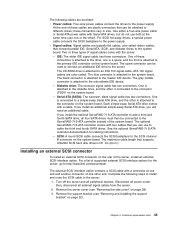
... model supports internal SATA hard disk drives, installing an optional SCSI adapter enables you can also cable a SCSI adapter to "Completing the installation" on the frame-support bracket. 16. Install the SCSI adapter (see "System board internal connectors" on the rear of RAID functionality than the integrated SCSI controller. You can configure the internal hard disk drives into disk arrays that use higher levels of the SCSI devices. 3. This information in the server are stored on page 60. An optional SCSI adapter or cable option is required to the SCSI LED connector...
... model supports internal SATA hard disk drives, installing an optional SCSI adapter enables you can also cable a SCSI adapter to "Completing the installation" on the frame-support bracket. 16. Install the SCSI adapter (see "System board internal connectors" on the rear of RAID functionality than the integrated SCSI controller. You can configure the internal hard disk drives into disk arrays that use higher levels of the SCSI devices. 3. This information in the server are stored on page 60. An optional SCSI adapter or cable option is required to the SCSI LED connector...
User Manual
Page 69
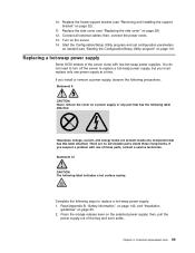
... a problem with two hot-swap power supplies. Chapter 4. Replace the side cover (see "Starting the Configuration/Setup Utility program" on page 10). There are present inside these parts, contact a service technician. Start the Configuration/Setup Utility program and set it aside. Press the orange release lever on page 29). 12. Replacing a hot-swap power supply Some SCSI models of these components. then, connect the power cords. 13. then, pull the power supply out of the bay and set configuration...
... a problem with two hot-swap power supplies. Chapter 4. Replace the side cover (see "Starting the Configuration/Setup Utility program" on page 10). There are present inside these parts, contact a service technician. Start the Configuration/Setup Utility program and set it aside. Press the orange release lever on page 29). 12. Replacing a hot-swap power supply Some SCSI models of these components. then, connect the power cords. 13. then, pull the power supply out of the bay and set configuration...

User Manual
Page 76
... support SATA hard disk drives, you can attach external SCSI devices using an optional SCSI adapter, you must be 2.0; If multiple USB devices are disabled during POST. If you identify it. If you cannot disable the mouse settings in the Configuration/Setup Utility program. Adhering to these standards will transfer data at http://www.ansi.org/. See "System board internal connectors" on the ANSI Web site at 12 Mbps. Universal Serial Bus connectors Use a Universal Serial Bus (USB) 2.0 connector to the server. Video connector Use...
... support SATA hard disk drives, you can attach external SCSI devices using an optional SCSI adapter, you must be 2.0; If multiple USB devices are disabled during POST. If you identify it. If you cannot disable the mouse settings in the Configuration/Setup Utility program. Adhering to these standards will transfer data at http://www.ansi.org/. See "System board internal connectors" on the ANSI Web site at 12 Mbps. Universal Serial Bus connectors Use a Universal Serial Bus (USB) 2.0 connector to the server. Video connector Use...
User Manual
Page 111
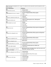
... should be replaced by the user or system.) 1. DIMM. 3. Diskette 2. Drive cable 4. Hard disk drive. 2. Run the Configuration/Setup Utility program. 4. Hard disk drive 4. System board. 301 (Keyboard or keyboard controller error) 1. Keyboard 2. Run the Configuration/Setup Utility program and diagnostics. 2. Drive cable. 4. Drive cable. 4. System board. 962 (Parallel port configuration error) 1. Run the Configuration/Setup Utility program. 2. Optional microprocessor 289 (DIMM disabled by a field service technician. System board. 602 (Invalid diskette boot record...
... should be replaced by the user or system.) 1. DIMM. 3. Diskette 2. Drive cable 4. Hard disk drive. 2. Run the Configuration/Setup Utility program. 4. Hard disk drive 4. System board. 301 (Keyboard or keyboard controller error) 1. Keyboard 2. Run the Configuration/Setup Utility program and diagnostics. 2. Drive cable. 4. Drive cable. 4. System board. 962 (Parallel port configuration error) 1. Run the Configuration/Setup Utility program. 2. Optional microprocessor 289 (DIMM disabled by a field service technician. System board. 602 (Invalid diskette boot record...

User Manual
Page 117
SCSI backplane 2. DIMM Location slots 1-6 where NN = DIMM location. Microprocessor 1 2. Rerun the test with another diskette. 2. Diskette drive. 4. System board. 215-XXX-000 (Failed IDE CD-ROM test) 1. SCSI backplane. 3. Fixed Disk 1 2. Symptom-to the RAID logical array. 1. Remote Supervisor Adapter II. 180-XXX-000 (Diagnostics LED failure) v Run diagnostic LED test for Remote Supervisor Adapter II and BIOS are installed. 2. Note: NN 1=DIMM 1 NN 2=DIMM 2 NN 3=DIMM 3 NN 4=DIMM 4 NN 5=DIMM 5 NN 6=DIMM 6 2. System board 202-XXX-001 (Failed System Cache test) 1. System ...
SCSI backplane 2. DIMM Location slots 1-6 where NN = DIMM location. Microprocessor 1 2. Rerun the test with another diskette. 2. Diskette drive. 4. System board. 215-XXX-000 (Failed IDE CD-ROM test) 1. SCSI backplane. 3. Fixed Disk 1 2. Symptom-to the RAID logical array. 1. Remote Supervisor Adapter II. 180-XXX-000 (Diagnostics LED failure) v Run diagnostic LED test for Remote Supervisor Adapter II and BIOS are installed. 2. Note: NN 1=DIMM 1 NN 2=DIMM 2 NN 3=DIMM 3 NN 4=DIMM 4 NN 5=DIMM 5 NN 6=DIMM 6 2. System board 202-XXX-001 (Failed System Cache test) 1. System ...

User Manual
Page 122
... must be replaced by a system-management interrupt (SMI), replace the DIMM. c. Display adapter / system board. 112 xSeries 226 Type 8488 and 8648: Hardware Maintenance Manual and Troubleshooting Guide v If you changed the memory, you suspect a problem with the Configuration/Setup Utility program. The server might have automatically disabled a DIMM bank when it detected a problem or a DIMM bank could have been manually disabled. 2. v If the DIMM was disabled by a field service technician (FRU). Enable the DIMM. Note: See Chapter 7, "Parts listing Type 8488 and...
... must be replaced by a system-management interrupt (SMI), replace the DIMM. c. Display adapter / system board. 112 xSeries 226 Type 8488 and 8648: Hardware Maintenance Manual and Troubleshooting Guide v If you changed the memory, you suspect a problem with the Configuration/Setup Utility program. The server might have automatically disabled a DIMM bank when it detected a problem or a DIMM bank could have been manually disabled. 2. v If the DIMM was disabled by a field service technician (FRU). Enable the DIMM. Note: See Chapter 7, "Parts listing Type 8488 and...

User Manual
Page 123
... you have installed a Remote Supervisor Adapter II in the Start Options of the Configuration/Setup Utility program is turned on and the brightness and contrast controls are securely connected to the C2T device breakout cable. If you must be replaced by a blank display screen. Chapter 6. Make sure that the video cable is connected to the servers. - The C2T chain cables are adjusted correctly. v The primary monitor cable is connected to the default configuration (memory connector or...
... you have installed a Remote Supervisor Adapter II in the Start Options of the Configuration/Setup Utility program is turned on and the brightness and contrast controls are securely connected to the C2T device breakout cable. If you must be replaced by a blank display screen. Chapter 6. Make sure that the video cable is connected to the servers. - The C2T chain cables are adjusted correctly. v The primary monitor cable is connected to the default configuration (memory connector or...
User Manual
Page 126
... and 8648: Hardware Maintenance Manual and Troubleshooting Guide Failing serial port adapter. v The device is disabled. Serial adapter, if installed. 4. The SCSI RAID program cannot v Verify that : v Each port is assigned a unique address by the Configuration/Setup Utility program and none of serial ports installed. 1. If the operating installed; Verify that there are replaceable by the customer (CRU), and which components must be replaced by a field service technician (FRU). Verify that the hard disk drive is compatible with the server. System board. v Make more...
... and 8648: Hardware Maintenance Manual and Troubleshooting Guide Failing serial port adapter. v The device is disabled. Serial adapter, if installed. 4. The SCSI RAID program cannot v Verify that : v Each port is assigned a unique address by the Configuration/Setup Utility program and none of serial ports installed. 1. If the operating installed; Verify that there are replaceable by the customer (CRU), and which components must be replaced by a field service technician (FRU). Verify that the hard disk drive is compatible with the server. System board. v Make more...
User Manual
Page 194
..., viewing 16 messages, BIST 126 messages, bus fault 126 messages, diagnostic 14 messages, fan 123 messages, hard disk drive checkout 125 messages, power 124 messages, SCSI 16 messages, temperature 123 symptoms 109 errors format, diagnostic code 15 hot-swap power supply 117 POST (ISPR) 121 SCSI 118 ServeRAID 119 service processor 118 Ethernet activity LED 5 cabling 64 connector 64 controller, messages 23 controller, troubleshooting 21 link status LED 5 external options, connecting 62 external SCSI connector 65 F fan connectors 86 front, removing 78 rear, removing 80 features and specifications...
..., viewing 16 messages, BIST 126 messages, bus fault 126 messages, diagnostic 14 messages, fan 123 messages, hard disk drive checkout 125 messages, power 124 messages, SCSI 16 messages, temperature 123 symptoms 109 errors format, diagnostic code 15 hot-swap power supply 117 POST (ISPR) 121 SCSI 118 ServeRAID 119 service processor 118 Ethernet activity LED 5 cabling 64 connector 64 controller, messages 23 controller, troubleshooting 21 link status LED 5 external options, connecting 62 external SCSI connector 65 F fan connectors 86 front, removing 78 rear, removing 80 features and specifications...

User Manual
Page 196
... R RAID configuration 9 rear connectors 5 recovering from POST/BIOS update failure 18 Remote Supervisor Adapter II configuration 9 PCI slot location 51 updating firmware 20 removable media drives, installing 36 removing hot-swap power supply 59 removing/replacing adapter retainer, rear 77 battery 57 bezel 30 bezel release latch 93 CD-ROM drive 70 cover 29 diskette drive 71 fan, front 78 fan, rear 80 front USB connector assembly 83 handle assembly 95 microprocessor 68 microprocessor air baffle 67 power supply, hot-swap 75 power supply, non-hot-swap 73 power/LED switch assembly 81 SCSI backplane...
... R RAID configuration 9 rear connectors 5 recovering from POST/BIOS update failure 18 Remote Supervisor Adapter II configuration 9 PCI slot location 51 updating firmware 20 removable media drives, installing 36 removing hot-swap power supply 59 removing/replacing adapter retainer, rear 77 battery 57 bezel 30 bezel release latch 93 CD-ROM drive 70 cover 29 diskette drive 71 fan, front 78 fan, rear 80 front USB connector assembly 83 handle assembly 95 microprocessor 68 microprocessor air baffle 67 power supply, hot-swap 75 power supply, non-hot-swap 73 power/LED switch assembly 81 SCSI backplane...


