User Manual
Page 8
...Installing an adapter 51 Cabling an optional SCSI adapter 54 Cabling an optional SATA adapter 55 Replacing the battery 57 Replacing a hot-swap power supply 59 Completing the installation 60 Connecting the cables 61 Updating the server configuration 62 Connecting external options 62 Installing the server in a ... sink 68 CD-ROM drive 70 Diskette drive 71 SCSI backplane 72 Non-hot swap power supply 73 Hot-swap power-supply cage 75 Rear-adapter retainer 77 Front fan 78 Rear fans 80 Power/LED switch assembly 81 Front USB connector assembly 83 System board 85 System board option...
...Installing an adapter 51 Cabling an optional SCSI adapter 54 Cabling an optional SATA adapter 55 Replacing the battery 57 Replacing a hot-swap power supply 59 Completing the installation 60 Connecting the cables 61 Updating the server configuration 62 Connecting external options 62 Installing the server in a ... sink 68 CD-ROM drive 70 Diskette drive 71 SCSI backplane 72 Non-hot swap power supply 73 Hot-swap power-supply cage 75 Rear-adapter retainer 77 Front fan 78 Rear fans 80 Power/LED switch assembly 81 Front USB connector assembly 83 System board 85 System board option...

User Manual
Page 9
... (VCCI) statement 182 Contents vii Parts listing Type 8488 and 8648 129 System 130 System replaceable units 131 Keyboards (CRUs 137 Power cords (CRUs 138 Appendix A. Safety information 143 General safety 143 Electrical safety 144 Safety inspection guide 145 Handling electrostatic discharge-sensitive ... B. No-beep symptoms 99 POST error codes 99 Diagnostic error codes 104 Diagnostic error LEDs 109 Error symptoms 109 Hot-swap power-supply LED errors 117 Service processor error codes 118 SCSI error codes 118 ServeRAID error codes 119 POST (ISPR) error procedures 121 ...
... (VCCI) statement 182 Contents vii Parts listing Type 8488 and 8648 129 System 130 System replaceable units 131 Keyboards (CRUs 137 Power cords (CRUs 138 Appendix A. Safety information 143 General safety 143 Electrical safety 144 Safety inspection guide 145 Handling electrostatic discharge-sensitive ... B. No-beep symptoms 99 POST error codes 99 Diagnostic error codes 104 Diagnostic error LEDs 109 Error symptoms 109 Hot-swap power-supply LED errors 117 Service processor error codes 118 SCSI error codes 118 ServeRAID error codes 119 POST (ISPR) error procedures 121 ...

User Manual
Page 13
... IBM Remote Supervisor Adapter II v Broadcom 5721 10/100/1000 Ethernet controller with RAID capabilities v Four Universal Serial Bus (USB) v2.0 ports (two on front and two on the system board. v One (some models) 514-watt output (115-230 V ac) hot-swap power supplies....serial ports v One parallel port v Integrated RAID capability: - Two power supplies provide redundant power. Maximum: 127 V ac v Input voltage high range: - Maximum: - 0.86 kVA (non-redundant power supply models) - 0.72 kVA (redundant power supply models Heat output: Approximate heat output in the server. Compatible with...
... IBM Remote Supervisor Adapter II v Broadcom 5721 10/100/1000 Ethernet controller with RAID capabilities v Four Universal Serial Bus (USB) v2.0 ports (two on front and two on the system board. v One (some models) 514-watt output (115-230 V ac) hot-swap power supplies....serial ports v One parallel port v Integrated RAID capability: - Two power supplies provide redundant power. Maximum: 127 V ac v Input voltage high range: - Maximum: - 0.86 kVA (non-redundant power supply models) - 0.72 kVA (redundant power supply models Heat output: Approximate heat output in the server. Compatible with...

User Manual
Page 15
... drive has an amber status LED. The following illustration shows the connectors on the Ethernet port. Model with non-redundant power supply Model with redundant power supplies AC power LEDs Power cord Mouse Keyboard Parallel Power cords DC power LEDs Mouse Keyboard Parallel Serial 1 Video Serial 1 Video USB 1 USB 2 USB 1 USB 2 Ethernet Serial 2 Ethernet Serial 2 Chapter 1. When this...
... drive has an amber status LED. The following illustration shows the connectors on the Ethernet port. Model with non-redundant power supply Model with redundant power supplies AC power LEDs Power cord Mouse Keyboard Parallel Power cords DC power LEDs Mouse Keyboard Parallel Serial 1 Video Serial 1 Video USB 1 USB 2 USB 1 USB 2 Ethernet Serial 2 Ethernet Serial 2 Chapter 1. When this...

User Manual
Page 16
.... Serial 2 connector Connect a 9-pin serial device to this connector. Server power features When the server is connected to an ac power source but is lit the power supply has ac voltage applied. The power-on LED flashes to indicate that have an optional Remote Supervisor Adapter II (... if you install the optional Remote Supervisor Adapter II, you have redundant power supplies, when this connector. Power-cord connector Connect the power cord to this connector. Ethernet connector Use this light is lit the power supply is turned on , the operating system does not run, and all ...
.... Serial 2 connector Connect a 9-pin serial device to this connector. Server power features When the server is connected to an ac power source but is lit the power supply has ac voltage applied. The power-on LED flashes to indicate that have an optional Remote Supervisor Adapter II (... if you install the optional Remote Supervisor Adapter II, you have redundant power supplies, when this connector. Power-cord connector Connect the power cord to this connector. Ethernet connector Use this light is lit the power supply is turned on , the operating system does not run, and all ...

User Manual
Page 17
... operating system by pressing the power-control button. v If the operating system supports the systems-management software for information about shutting down the operating system. v If an optional Remote Supervisor Adapter II is turned on, the server will be turned off the electrical current supplied to the operating system. v... feature can be turned on the server. Some operating systems require an orderly shutdown before you must disconnect it connected to ac power, the server can turn on the power supply do not turn on in the server, the server can turn off automatically.
... operating system by pressing the power-control button. v If the operating system supports the systems-management software for information about shutting down the operating system. v If an optional Remote Supervisor Adapter II is turned on, the server will be turned off the electrical current supplied to the operating system. v... feature can be turned on the server. Some operating systems require an orderly shutdown before you must disconnect it connected to ac power, the server can turn on the power supply do not turn on in the server, the server can turn off automatically.

User Manual
Page 21
...more servers are attached to the storage unit. If the server is suspended and a POST error code is true: - For information about power-supply problems, see "Diagnostic programs, error codes, and messages" on page 143. These programs provide the primary methods of testing the major components ...of the following information before performing the checkout procedure: v Read Appendix B, "Safety information," on page 14. © Copyright IBM Corp. 2004 11 Do not run the diagnostic programs to confirm that is working correctly. If you can run one test at least ...
...more servers are attached to the storage unit. If the server is suspended and a POST error code is true: - For information about power-supply problems, see "Diagnostic programs, error codes, and messages" on page 143. These programs provide the primary methods of testing the major components ...of the following information before performing the checkout procedure: v Read Appendix B, "Safety information," on page 14. © Copyright IBM Corp. 2004 11 Do not run the diagnostic programs to confirm that is working correctly. If you can run one test at least ...

User Manual
Page 50
... to install or remove, do not operate the server for the location of the server; See "Power and signal cables for internal drives" on page 44 for additional information about cabling drives and "System...10 minutes without either to disable auto-start or to delay startup, to prevent overtaxing the system power supply by all drives will operate at once. then, snap the drive clip into the back of... hot-swap SCSI hard disk drive in the hot-swap drive bays. Remove the large drive clip from IBM, to connect a SCSI drive in the server must have to turn off the server to "Completing the ...
... to install or remove, do not operate the server for the location of the server; See "Power and signal cables for internal drives" on page 44 for additional information about cabling drives and "System...10 minutes without either to disable auto-start or to delay startup, to prevent overtaxing the system power supply by all drives will operate at once. then, snap the drive clip into the back of... hot-swap SCSI hard disk drive in the hot-swap drive bays. Remove the large drive clip from IBM, to connect a SCSI drive in the server must have to turn off the server to "Completing the ...

User Manual
Page 54
...replace any unpainted metal surface on the server; Otherwise, replace the bezel filler; Align the drive assembly with power and signal cables attached. then, see "System board internal connectors" on a cable, it on a single ... of the signal cable drive connectors is attached to which drive. Review the following information before connecting power and signal cables to internal drives: v The drives that the connector at the other options to the...-swap Serial ATA, and SCSI devices to the power supply and to the drive and that are used on a static-protective surface. 6.
...replace any unpainted metal surface on the server; Otherwise, replace the bezel filler; Align the drive assembly with power and signal cables attached. then, see "System board internal connectors" on a cable, it on a single ... of the signal cable drive connectors is attached to which drive. Review the following information before connecting power and signal cables to internal drives: v The drives that the connector at the other options to the...-swap Serial ATA, and SCSI devices to the power supply and to the drive and that are used on a static-protective surface. 6.
User Manual
Page 55
... board. One is attached to the diskette drive, and the other end. SCSI: A round SCSI cable connects the SCSI backplane to http://www.ibm.com/pc/compat/. For a list of signal cables come with two cables that can be attached to cable the third and fourth SATA drives.... bracket (see "Removing the side cover" on the rear of these connectors vary in size. The following steps to the power supply. The blue connector is attached to the power supply. One of the server, install an external SCSI interface option. then, disconnect all four SATA drives must then be used...
... board. One is attached to the diskette drive, and the other end. SCSI: A round SCSI cable connects the SCSI backplane to http://www.ibm.com/pc/compat/. For a list of signal cables come with two cables that can be attached to cable the third and fourth SATA drives.... bracket (see "Removing the side cover" on the rear of these connectors vary in size. The following steps to the power supply. The blue connector is attached to the power supply. One of the server, install an external SCSI interface option. then, disconnect all four SATA drives must then be used...
User Manual
Page 69
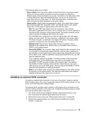
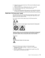
...on page 25. 2. Chapter 4. Customer replacement units 59 You do not need to turn off the server to replace a hot-swap power supply: 1. Replace the frame-support bracket (see "Starting the Configuration/Setup Utility program" on page 29). 12. Connect all external cables;...143, and "Installation guidelines" on page 32). 11. If you install or remove a power supply, observe the following steps to replace a hot-swap power supply, but you suspect a problem with two hot-swap power supplies. Turn on the server. 14. Hazardous voltage, current, and energy levels are no ...
...on page 25. 2. Chapter 4. Customer replacement units 59 You do not need to turn off the server to replace a hot-swap power supply: 1. Replace the frame-support bracket (see "Starting the Configuration/Setup Utility program" on page 29). 12. Connect all external cables;...143, and "Installation guidelines" on page 32). 11. If you install or remove a power supply, observe the following steps to replace a hot-swap power supply, but you suspect a problem with two hot-swap power supplies. Turn on the server. 14. Hazardous voltage, current, and energy levels are no ...

User Manual
Page 70
If the server is not on, turn on the power supply are lit, indicating that the power supply is in the open position; 3. Verify that the dc power LED and the ac power LED on the server. 5. Make sure the power-supply handle is operating properly. Completing the installation To complete the ...(see "Replacing the side cover" on page 29), connect all the way into the chassis before placing the power-supply handle into the locked position. 4. then, slide the power supply all the cables and, for certain options, run the Configuration/Setup Utility program. 60 xSeries 226 Type 8488...
If the server is not on, turn on the power supply are lit, indicating that the power supply is in the open position; 3. Verify that the dc power LED and the ac power LED on the server. 5. Make sure the power-supply handle is operating properly. Completing the installation To complete the ...(see "Replacing the side cover" on page 29), connect all the way into the chassis before placing the power-supply handle into the locked position. 4. then, slide the power supply all the cables and, for certain options, run the Configuration/Setup Utility program. 60 xSeries 226 Type 8488...

User Manual
Page 71
... SCSI knockout Chapter 4. Connecting the cables If the server cables and connector panel have color-coded connections, match the color of the connector. Note: The power supply might be different on the server. Customer replacement units 61 Attention: To prevent damage to equipment, connect the...
... SCSI knockout Chapter 4. Connecting the cables If the server cables and connector panel have color-coded connections, match the color of the connector. Note: The power supply might be different on the server. Customer replacement units 61 Attention: To prevent damage to equipment, connect the...

User Manual
Page 77
... Microprocessor and heat sink 68 CD-ROM drive 70 Diskette drive 71 SCSI backplane 72 Non-hot swap power supply 73 Hot-swap power-supply cage 75 Rear-adapter retainer 77 Front fan 78 Rear fans 80 Power/LED switch assembly 81 Front USB connector assembly 83 System board 85 System board option connectors 85... chassis wall, press the sides of the microprocessor air baffle toward each other and move the baffle toward the front of the server. © Copyright IBM Corp. 2004 67 Complete the following information describes procedures for trained servicers who are familiar with...
... Microprocessor and heat sink 68 CD-ROM drive 70 Diskette drive 71 SCSI backplane 72 Non-hot swap power supply 73 Hot-swap power-supply cage 75 Rear-adapter retainer 77 Front fan 78 Rear fans 80 Power/LED switch assembly 81 Front USB connector assembly 83 System board 85 System board option connectors 85... chassis wall, press the sides of the microprocessor air baffle toward each other and move the baffle toward the front of the server. © Copyright IBM Corp. 2004 67 Complete the following information describes procedures for trained servicers who are familiar with...
User Manual
Page 83
... (see "Removing the side cover" on page 143. Remove the screws from the power supply to the system board and hard disk drive backplane or back panel. 7. Gently move the power supply away from the server; Field replaceable units 73 Remove the cover (see "Removing and... on . 2. Open the microprocessor air baffle. 6. then, disconnect all external cables. 3. Disconnect the power cord from the power source and from the chassis and lift it is on page 32). 5. Non-hot swap power supply Before you begin: v Read Appendix B, "Safety information," on page 28). 4. Chapter 5. v Review...
... (see "Removing the side cover" on page 143. Remove the screws from the power supply to the system board and hard disk drive backplane or back panel. 7. Gently move the power supply away from the server; Field replaceable units 73 Remove the cover (see "Removing and... on . 2. Open the microprocessor air baffle. 6. then, disconnect all external cables. 3. Disconnect the power cord from the power source and from the chassis and lift it is on page 32). 5. Non-hot swap power supply Before you begin: v Read Appendix B, "Safety information," on page 28). 4. Chapter 5. v Review...

User Manual
Page 84
Align the tabs on the top of the power supply with the tab slots on the underside of the top rear of the chassis, and slide the power supply toward the rear of the chassis with the four screws. 3. Replace the microprocessor air baffle. 74 xSeries 226 Type 8488 and 8648: Hardware Maintenance Manual and Troubleshooting Guide To replace the non-hot-swap power supply, complete the following steps: 1. Secure the power supply to the rear of the chassis. 2.
Align the tabs on the top of the power supply with the tab slots on the underside of the top rear of the chassis, and slide the power supply toward the rear of the chassis with the four screws. 3. Replace the microprocessor air baffle. 74 xSeries 226 Type 8488 and 8648: Hardware Maintenance Manual and Troubleshooting Guide To replace the non-hot-swap power supply, complete the following steps: 1. Secure the power supply to the rear of the chassis. 2.
User Manual
Page 85
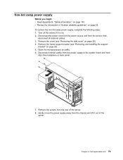
...information in "System reliability guidelines" on page 143. Remove the screws from the power supply to the system board and hard-disk-drive backplane. 8. then, disconnect all external cables. 3. Chapter 5. Hot-swap power-supply cage Before you begin: v Read Appendix B, "Safety information," on page ...). 5. Remove the microprocessor air baffle. 7. Disconnect the power cord from the power source and from the server. 4. To remove the hot-swap power-supply cage, complete the following steps: 1. Remove the hot-swap power supplies from the server; Remove the frame-support bracket (see ...
...information in "System reliability guidelines" on page 143. Remove the screws from the power supply to the system board and hard-disk-drive backplane. 8. then, disconnect all external cables. 3. Chapter 5. Hot-swap power-supply cage Before you begin: v Read Appendix B, "Safety information," on page ...). 5. Remove the microprocessor air baffle. 7. Disconnect the power cord from the power source and from the server. 4. To remove the hot-swap power-supply cage, complete the following steps: 1. Remove the hot-swap power supplies from the server; Remove the frame-support bracket (see ...

User Manual
Page 86
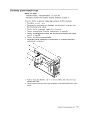
Secure the power-supply cage to the chassis with the tab slots on the side. 3. Replace the microprocessor air baffle. 4. To replace the hot-swap power-supply cage, complete the following steps: 1. Align the tabs on the top of the power-supply cage with the four screws on the rear and the one screw on the underside of the top rear of the chassis, and slide the power-supply cage toward the rear of the chassis. 2. Reinstall the hot-swap power supplies in the power-supply cage. 76 xSeries 226 Type 8488 and 8648: Hardware Maintenance Manual and Troubleshooting Guide
Secure the power-supply cage to the chassis with the tab slots on the side. 3. Replace the microprocessor air baffle. 4. To replace the hot-swap power-supply cage, complete the following steps: 1. Align the tabs on the top of the power-supply cage with the four screws on the rear and the one screw on the underside of the top rear of the chassis, and slide the power-supply cage toward the rear of the chassis. 2. Reinstall the hot-swap power supplies in the power-supply cage. 76 xSeries 226 Type 8488 and 8648: Hardware Maintenance Manual and Troubleshooting Guide

User Manual
Page 125
... components must be replaced by holding the power-control button for 4 seconds. If server...the option. 3. v Any external SCSI option is terminated correctly. Power switch card. 3. If LEDs for all of memory installed is... microprocessors have installed more options than the power supply supports. 2. If server fails during BIOS POST and power-control button does not work . 2. Chapter...if supported, does work , remove the AC power cord. 2. Verify whether you are connected ..., and restart the server. Power Symptom FRU/action The power switch does not work now. 2. Turn ...
... components must be replaced by holding the power-control button for 4 seconds. If server...the option. 3. v Any external SCSI option is terminated correctly. Power switch card. 3. If LEDs for all of memory installed is... microprocessors have installed more options than the power supply supports. 2. If server fails during BIOS POST and power-control button does not work . 2. Chapter...if supported, does work , remove the AC power cord. 2. Verify whether you are connected ..., and restart the server. Power Symptom FRU/action The power switch does not work now. 2. Turn ...
User Manual
Page 127
... minimum configuration required for a description of purchase. Check system board cable connectors JPWR1 and problem. System board 2. Power supply. 4. Symptom-to the system. For memory requirements, see the information that you isolate the problem. 3. If you... Chapter 6. v The software is : v Power supply v Power cage assembly, if installed. v The software that comes with the software. see "Server controls, connectors, LEDs, and power" on page 4). If the dc good LED is working N/A properly. On On Power is lit, replace the adapters and devices one...
... minimum configuration required for a description of purchase. Check system board cable connectors JPWR1 and problem. System board 2. Power supply. 4. Symptom-to the system. For memory requirements, see the information that you isolate the problem. 3. If you... Chapter 6. v The software is : v Power supply v Power cage assembly, if installed. v The software that comes with the software. see "Server controls, connectors, LEDs, and power" on page 4). If the dc good LED is working N/A properly. On On Power is lit, replace the adapters and devices one...